building a cicso network for windows 2000 phần 3 ppt
Bạn đang xem bản rút gọn của tài liệu. Xem và tải ngay bản đầy đủ của tài liệu tại đây (8.31 MB, 60 trang )
94 Chapter 3 • Cisco Hardware and IOS Basics
www.syngress.com
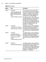
Table 3.2 Continued
Model Ports Comments
1602 R
1603 R
1604 R
1605 R
1 Ethernet
1 Serial w/integrated 56
Kbps CSU/DSU (Channel
Service Unit/Data Service
Unit)
1 WAN interface card slot
1 Ethernet
1 ISDN BRI (S/T interface)
1 WAN interface card slot
1 Ethernet
1 ISDN BRI with inte-
grated NT1 (U interface)
1 S-bus port for ISDN
phones
1 WAN interface card slot
2 Ethernet
1 WAN interface card slot
The serial port can be used to sup-
port asynchronous serial connections
of up to 115.2 Kbps. It also provides
support for synchronous serial con-
nections (Frame Relay, Switched 56,
and X.25) of up to 2.048 Mbps.
The WAN interface cards available for
the WAN interface slot include Serial
(asynchronous and synchronous),
T1/Fractional T1 CSU/DSU, 56/64 Kbps
four-wire CSU/DSU, ISDN BRI with S/T
interface, and ISDN BRI with inte-
grated NT1, U interface.
The WAN interface cards available for
the WAN interface slot include Serial
(asynchronous and synchronous),
T1/Fractional T1 CSU/DSU, 56/64 Kbps
four-wire CSU/DSU, ISDN BRI leased
line.
The WAN interface cards available for
the WAN interface slot include Serial
(asynchronous and synchronous),
T1/Fractional T1 CSU/DSU, 56/64 Kbps
four-wire CSU/DSU, ISDN BRI leased
line.
The WAN interface cards available for
the WAN interface slot include: Serial
(asynchronous and synchronous),
T1/Fractional T1 CSU/DSU, 56/64 Kbps
four-wire CSU/DSU, ISDN BRI with S/T
interface, and ISDN BRI with inte-
grated NT1, U interface.
71_BCNW2K_03 9/12/00 3:59 PM Page 94
Cisco Hardware and IOS Basics • Chapter 3 95
800 Series
The 800 series (shown in Figure 3.12) consists of 11 different models
including the 801, 801 CAPI, 802, 802 IDSL, 803, 803 CAPI, 804, 804
IDSL, 805, 827, and 827-4V. This series of routers is designed for small
offices as well as telecommuters. The 800 series provides integrated voice
and data support as well as security with VPNs. It can be confusing trying
to compare the differences in the different models within the 800 series so
Table 3.3 logically illustrates the differences.
www.syngress.com
Figure 3.12 The front of a Cisco 800 Series router
Table 3.3 Port Configurations of the Cisco 800 Series Routers
Model Ports Comments
801
801 CAPI
802
802 IDSL
803
803 CAPI
1 Ethernet
1 IDSN BRI (S/T interface)
1 Ethernet
1 IDSN BRI (S/T interface)
1 Ethernet
1 IDSN BRI with inte-
grated NT1 (U interface)
1 Ethernet
1 IDSL (ISDN Digital
Subscriber Line) with inte-
grated NT1 (U interface)
4-port Ethernet hub
1 IDSN BRI (S/T interface)
2 Analog RJ-11
4-port Ethernet hub
1 IDSN BRI (S/T interface)
2 Analog RJ-11
Provides support for European ISDN
and the Common Application
Programming Interface (CAPI).
Supports line rates up to 144 Kbps.
Supports call waiting, call-waiting
cancel, call hold, call retrieve, three-
way conferencing, and call transfer.
Provides support for European ISDN
and the Common Application
Programming Interface (CAPI).
Continued
71_BCNW2K_03 9/12/00 3:59 PM Page 95
96 Chapter 3 • Cisco Hardware and IOS Basics
Cisco IOS
The “brains” of both Cisco switches and Cisco routers is the Internetwork
Operating System (IOS). Without the IOS the hardware might as well be
used as boat anchors. The IOS is responsible for everything from allowing
the configuration of interfaces, to security using ACLs, and everything in
between.
Differences in Switch and Router IOSs
The term Internetwork Operating System can be misleading—you may
think that all IOSs are created equally. In reality, there is a difference in
the IOSs used by switches and routers. Switch IOSs can support the con-
figuration of VLANs, VTP, and items unique to switches, whereas router
IOSs provide configuration support for various WAN configurations. The
IOSs do have some commonality as they are used to configure Ethernet
(and other) interfaces that can be present on both types of equipment.
www.syngress.com
Table 3.3 Continued
Model Ports Comments
804
804 IDSL
805
827
827-4V
4-port Ethernet hub
1 IDSN BRI with inte-
grated NT1 (U interface)
2 Analog RJ-11
4-port Ethernet hub
1 IDSL with integrated
NT1 (U interface)
1 Ethernet
1 Serial
1 Ethernet
1 ADSL (Asymmetric
Digital Subscriber Line)
1 Ethernet
1 ADSL
4 Analog RJ-11
Supports call waiting, call-waiting
cancel, call hold, call retrieve, three-
way conferencing, and call transfer.
Supports line rates up to 144 Kbps.
Supports both synchronous serial
(Frame Relay, leased line, and X.25)
connections up to 512 Kbps and
asynchronous dial-up connections.
Ideal for up to 20 users in a small
office.
Ideal for up to 20 users in a small
office.
71_BCNW2K_03 9/12/00 3:59 PM Page 96
Cisco Hardware and IOS Basics • Chapter 3 97
Router Feature Sets
Not only are there differences in switch and router IOSs, but there are
even different feature sets among the router IOSs geared toward different
functions. The decisions don’t stop after you decide on the routers for your
Windows 2000 network infrastructure. You need to determine which IOS
feature set meets the needs for the routers in question since each feature
set contains a specific set of Cisco IOS features. Let’s examine some of the
different feature sets that you need to be aware of.
Enterprise
The Enterprise feature set provides the widest range of features available
in the IOS. Some of the features normally found within the Enterprise fea-
ture set, which can vary depending on the hardware platform, are support
for Apollo Domain, Banyan VINES, Frame Relay SVC support, Intermediate
System-to-Intermediate System (IS-IS), Kerberos V client support, and
other items normally seen in the enterprise environment.
IP/IPX/IBM
The IP/IPX/IBM feature set provides support for adding IP, IPX, and IBM
routing support to the router. The IBM features include support for
Systems Network Architecture (SNA) bisync, caching and filtering, NetView
Native Service Point, as well as numerous other items.
IP Plus
The IP Plus feature set adds items related to the Internet Protocol. Some of
the items present in the IP Plus feature set include Network Address
Translation (NAT), Hot Standby Router Protocol (HSRP), Voice-over IP
(VoIP), and ATM LAN Emulation (LANE). Of course these features can vary
and are dependent on the hardware on which the IOS is running.
Firewall Feature Set
The Firewall feature set provides additional security functionality to the
routers on which it is running. It provides not only firewall features such
as stateful, application-based filtering, but also intrusion detection. Alerts
can be configured to provide reporting in real-time. The Firewall feature set
can be combined with IP Security (IPSec) and Layer 2 Tunneling Protocol to
provide a complete virtual private network environment.
Memory Requirements
The amount of memory required for your router depends in part on the
feature set you plan to use. For example, on a 3620 router with the
www.syngress.com
71_BCNW2K_03 9/12/00 3:59 PM Page 97
98 Chapter 3 • Cisco Hardware and IOS Basics
Enterprise feature set you need a minimum of 16MB of flash memory and
64MB of dynamic random access memory (DRAM). If you decide instead to
use the IP/H323 feature set, the router requires a minimum of 8MB of
flash memory and 48MB of DRAM. Of course these are just the minimum
requirements for the feature set and you may require more memory
depending on the use of the router within your Windows 2000 network
infrastructure.
Command Line Interface (CLI)
The most common method of interacting with the router is through the
command line interface provided by the Cisco IOS software. Every Cisco
router has a console port that can be directly connected to a PC or ter-
minal so that you can type commands at the keyboard and receive output
on a terminal screen. The part of the Cisco IOS software that provides the
user interface and interprets the commands you type is called the com-
mand executive, or EXEC.
www.syngress.com
Enhanced Editing Keys
Some of the commands you will type in the CLI can be very long.
Cisco has been thoughtful enough to include a series of keystrokes that
you can use to navigate around on the command line. This feature is
known as enhanced editing, and for those of you familiar with UNIX,
you will recognize the following keystrokes as the EMACS editing
keystrokes.
CTRL-A Go to the beginning of the line
CTRL-E Go to the end of the line
ESC-B Go back to the beginning of the previous word
ESC-F Go forward to the beginning of the next word
CTRL-B Go back one character
CTRL-F Go forward one character
These are not the only keys available to you in the IOS; I encourage
you to research the documentation that came with your router for other
time-saving keystrokes.
For IT Professionals
71_BCNW2K_03 9/12/00 3:59 PM Page 98
Cisco Hardware and IOS Basics • Chapter 3 99
How to Get Around in the IOS
Moving around the IOS is similar to typing at an MS-DOS prompt on a PC.
You don’t change directories as you do on a PC, but you can change the
mode you are operating in as well as various configuration settings.
The IOS has a context-sensitive Help feature built in. This is a feature
you will learn to depend on as you work with the command line interface.
To enter the Help system all you need to do is type a ?. The screen will
show the commands that are available to you. This list changes depending
on the mode you are in within the IOS as well as on where you are in the
IOS when you enter the help system. You can also enter the help system if
you forget the syntax for a command. All you have to do is type the part of
the command you remember and then a ?. The help system will display
the options available to you at that point.
While in the IOS you do not have to type the full command name. You
can abbreviate commands to the point that it is unique so that the IOS
knows what you want to do. Look at the following example from a Catalyst
2924 switch in which the command show running-config has been abbre-
viated to sh ru. The IOS understands what you want to accomplish but
you have saved yourself a lot of typing!
2924Outside#sh ru
Building configuration
Current configuration:
!
version 11.2
no service pad
no service udp-small-servers
no service tcp-small-servers
!
hostname 2924Outside
!
enable secret 5 $1$.LeN$Cjuf.cxxxxxxxxxyu9YTKgU/
!
username kesnet privilege 15 password 7 xxxxxxxxxx 0 9
!
!
clock timezone Central 0
www.syngress.com
71_BCNW2K_03 9/12/00 3:59 PM Page 99
100 Chapter 3 • Cisco Hardware and IOS Basics
!
interface VLAN1
ip address 10.10.14.150 255.255.255.0
no ip route-cache
!
interface FastEthernet0/1
switchport access vlan 2
interface FastEthernet0/2
switchport access vlan 2
!
interface FastEthernet0/3
switchport access vlan 2
!
interface FastEthernet0/4
switchport access vlan 2
!
interface FastEthernet0/5
switchport access vlan 2
!
interface FastEthernet0/6
switchport access vlan 2
!
interface FastEthernet0/7
switchport access vlan 2
!
interface FastEthernet0/8
switchport access vlan 2
!
interface FastEthernet0/9
switchport access vlan 3
!
interface FastEthernet0/10
switchport access vlan 3
!
www.syngress.com
71_BCNW2K_03 9/12/00 3:59 PM Page 100
Cisco Hardware and IOS Basics • Chapter 3 101
interface FastEthernet0/11
switchport access vlan 3
!
interface FastEthernet0/12
switchport access vlan 3
!
interface FastEthernet0/13
switchport access vlan 3
!
interface FastEthernet0/14
switchport access vlan 3
!
interface FastEthernet0/15
switchport access vlan 3
!
interface FastEthernet0/16
switchport access vlan 3
!
interface FastEthernet0/17
switchport access vlan 3
!
interface FastEthernet0/18
switchport access vlan 3
!
interface FastEthernet0/19
switchport access vlan 3
!
interface FastEthernet0/20
switchport access vlan 3
!
interface FastEthernet0/21
switchport access vlan 3
!
interface FastEthernet0/22
www.syngress.com
71_BCNW2K_03 9/12/00 3:59 PM Page 101
102 Chapter 3 • Cisco Hardware and IOS Basics
switchport access vlan 3
!
interface FastEthernet0/23
switchport access vlan 2
!
interface FastEthernet0/24
switchport access vlan 3
ip default-gateway 10.10.14.1
snmp-server community XXXX RW
snmp-server chassis-id 0x0F
banner motd ^C
Access permitted to XXXXXXX personnel only all others must disconnect
immediately!!!
^C
!
line con 0
stopbits 1
line vty 0 4
access-class 100 in
password XXXXXXXX
login local
line vty 5 15
access-class 100 in
password XXXXXXXX
login local
!
end
Enable Mode
The IOS supports multiple modes. When you first log into a router you are
in user EXEC mode. This mode is the lowest level of access to the router,
and allows you to examine the status of most of the router’s configurable
components, see the contents of routing tables, and do basic nondisruptive
network troubleshooting. You cannot change the router’s configuration
while in user EXEC mode, nor can you view the contents of the router’s
configuration files. To do these things you must be in privileged EXEC
www.syngress.com
71_BCNW2K_03 9/12/00 3:59 PM Page 102
Cisco Hardware and IOS Basics • Chapter 3 103
mode. This mode is sometimes called the enable mode, since that is the
command you use to get this level of access. You can verify that you are in
enable mode by the # sign shown after the router name. At this level you
have full access to the router so you can do anything from viewing configu-
ration files to disrupting network traffic by rebooting the router.
ROMMON Mode
The ROM monitor (ROMMON) mode is used to boot the router or perform
diagnostic tests. There are two instances in which you enter ROMMON
mode: if the router does not find a valid system image, and if you pur-
posely interrupt the boot sequence by first using the reload command and
then pressing the Break key within 60 seconds of booting. Once in
ROMMON mode you can load an image from a Trivial File Transfer
Protocol (TFTP) server, perform a stack trace, as well as other actions.
When you want to exit ROMMON mode, simply type continue. This places
you in user EXEC mode. If you want to initialize the router, enter the com-
mand i. This command causes the bootstrap program to reinitialize the
router, clear the memory, and boot the system.
Normally the item everyone deals with when in ROMMON mode is the
configuration register. The configuration register is 16-bit and is modified
using the confreg command while in ROMMON mode. You may specify the
hexadecimal address of the item you want to change as a value of the con-
freg command or type confreg by itself to be prompted for each bit. For
example, the lowest four bits of the configuration register are used for the
boot field. This field determines whether the router boots from the net-
work, from Flash memory, manually, or from ROM.
Global vs Interface Mode on the CLI
To configure the router you must be in the correct mode. First you must
enter enable mode as all configurations are done from the privileged EXEC
mode. Once you are in privileged EXEC mode you may enter global configu-
ration mode. Use this mode to accomplish tasks such as naming your
router and configuring a banner message for users logging into the router.
Any configuration command that affects the operation of the entire router
would be entered in global configuration mode. To enter global configura-
tion mode, use the command configure terminal.
Of course not all of the router configuration can be done in global con-
figuration mode. To configure an interface you must go into the interface
configuration mode for the correct interface you want to configure. It is
easy to tell what configuration mode you are in as the router displays spe-
cial prompts. When you are in global configuration mode you will see the
following prompt:
www.syngress.com
71_BCNW2K_03 9/12/00 3:59 PM Page 103
104 Chapter 3 • Cisco Hardware and IOS Basics
RouterName (config)#
To move to the interface configuration mode you type interface <inter-
face id> at the config prompt as shown in the following example:
RouterName (config)# interface eth0
When you are in interface configuration mode you will see the following
prompt:
RouterName (config-if)#
QoS Functionality and How it Works on
Switches and Routers
Windows 2000 provides support for Quality of Service (QoS). But what
exactly is Quality of Service? QoS is a combination of mechanisms that
provide a specific level of traffic across disparate networks. This type of
service provides organizations with the following three benefits:
■
Lower network delays
■
Delays the need for additional bandwidth
■
Greater level of control over the network for the network adminis-
trator
Some of the components involved with QoS relate to the network infras-
tructure, such as switches and routers, as well as a method for classifying
network traffic and determining priority based upon predefined policies.
QoS as it relates to Windows 2000 focuses on the Resource Reservation
Protocol (RSVP).
RSVP
Resource Reservation Protocol is the host-to-host communication/negotia-
tion of the QoS requirements. Network devices, such as Cisco switches and
routers, will listen to the RSVP signaling between two hosts and determine
whether the user requesting service, quantity of resources, or type of ser-
vice being requested falls within the pre-established policies of the net-
work. Other networking devices do not listen to the RSVP signaling and
just let the traffic pass. Because RSVP is based upon host-to-host commu-
nication, there is some concern about its ability to scale sufficiently. RSVP
is covered in greater detail in Chapter 9.
www.syngress.com
71_BCNW2K_03 9/12/00 3:59 PM Page 104
Cisco Hardware and IOS Basics • Chapter 3 105
Queuing Techniques
RSVP is not the only way that Quality of Service is implemented within
Cisco routers. Various queuing techniques can be used so that when the
amount of traffic going through a particular interface is greater than the
interface’s bandwidth, the packets are queued. The priority of traffic
depends on the policy in place. Let’s examine the different queuing tech-
niques implemented in Cisco routers.
Weighted Fair Queuing
Weighted Fair Queuing is used primarily to manage low-bandwidth and
high-bandwidth traffic streams. Its queuing algorithm simultaneously
schedules low-bandwidth traffic to the front of the queue, and shares the
remaining bandwidth between high-bandwidth traffic streams. This is nec-
essary because some high-bandwidth traffic streams have a tendency to
act as a shuttle train by disallowing low-bandwidth data traffic its due
bandwidth. This scenario can often facilitate increased response time on
low-bandwidth networks, causing noticeable latency.
Priority Queuing
Priority Queuing was designed to support a very specific need. For some
applications, it is imperative that data is delivered on time and that band-
width is available, requiring a traffic prioritization scheme. Priority
Queuing is by far the most discriminating of the queuing services. Priority
Queuing can ensure correct delivery using a structure of four queues des-
ignated as high, medium, normal, and low. The queues apply the specified
traffic hierarchy and route packets toward designated queues. Of the four
queues available in Priority Queuing, the high queue has priority and is
always emptied first. If there is a packet in the high queue, it is sent imme-
diately. If there are no more packets in the high queue, then a packet is
sent from the medium queue. Before a second packet is sent from the
medium queue, the high queue is checked again. If there is data to be sent
in the high queue, the entire queue is emptied before the medium queue is
revisited. As you can see, lower-priority traffic may have problems getting
any transmit time, especially if higher priority queues are always full. The
main concept to remember here is queue priority. Higher priority queues
have precedence over all lower queues. This is the most important concept
to understand when deciding to use Priority Queuing. Priority Queuing
should be used only when certain types of traffic must have guaranteed
bandwidth over other types of traffic.
www.syngress.com
71_BCNW2K_03 9/12/00 3:59 PM Page 105
106 Chapter 3 • Cisco Hardware and IOS Basics
Custom Queuing
With Custom Queuing, by controlling the bandwidth that each of 16
custom queues use, you remove the potential for dropping low-priority
traffic with priority queuing. In Custom Queuing, a round-robin dis-
patching scheme sequentially services each of 16 queues. Each queue is
serviced until either the queue is emptied, or a queue threshold is reached.
Each queue can be sized differently to fine-tune additional control on
traffic flow. More specifically, the sizing of the queue is used to define the
byte-count allowed for transmission before the next queue gets a chance to
send its packets. The larger the queue, the more packets transmitted
during a cycle. A system queue is predefined by the Cisco IOS; it uses
queue 0. High-priority packets, such as keep-alives, use the system queue.
Class-based Weighted Fair Queuing
You can think of Class-based Weighted Fair Queuing as using the
strongest characteristics of two queuing techniques we have already dis-
cussed, Weighted Fair Queuing and Custom Queuing. Class-based
Weighted Fair Queuing gives higher weight to high-priority traffic just as
Weighted Fair Queuing does, but it determines the weight based upon the
classes that have been created on the interface. In this regard, the classes
are comparable to Custom Queues. Each interface can have up to 64
classes and each class is policy-based, in which you identify certain char-
acteristics of the traffic, such as the protocol, and allocate a portion of the
interface’s bandwidth for the traffic flow.
Traffic Shaping Techniques
Traffic shaping differs from the queuing methods we just discussed since it
is accomplished through policies defined within ACLs. Policies can be
based on a variety of characteristics such as the type of traffic, its source
address, its destination address, and other items. Another difference
between traffic shaping and queuing is that traffic flow is always affected
when traffic-shaping policies are used, even when the flow of traffic is not
packed. This is unlike queuing that is used when traffic is packed on an
interface.
www.syngress.com
71_BCNW2K_03 9/12/00 3:59 PM Page 106
Cisco Hardware and IOS Basics • Chapter 3 107
Summary
In this chapter we examined network basics with regard to the differences
between switches and routers. We learned that switches typically operate
at the data-link layer (Layer 2) and routers operate at the network layer
(Layer 3). We also examined the Hierarchical Design Model that consists of
the core, distribution, and access layers. We determined when it is appro-
priate to use switches and routers within your Windows 2000 network
infrastructure.
Next we examined a variety of switches available from Cisco including
the Catalyst 6500 series, Catalyst 5000 series, Catalyst 3500 series, and
Catalyst 2900 series. We saw that VLANs can break down the size of
broadcast domains. VLANs can utilize different trunking technologies,
including ISL and IEEE 802.1Q. The VLAN Trunk Protocol (VTP) allows you
to manage the configuration of the switches centrally within your network
by setting up a VTP server and VTP clients. We also identified that some
switches can operate at Layer 3 including the Catalyst 6000 series, which
uses the MSFC, and the Catalyst 5000 series, which uses the RSM.
Next we turned our attention to the routers that are available from
Cisco including the 7500 series, 7200 series, 3600 series, 1700 series,
1600 series, and 800 series. In this section we also reviewed different
LAN/WAN technologies.
The Cisco IOS, which is used by both switches and routers, was dis-
cussed next. We looked at some of the differences between switch and
router IOSs as well as different feature sets available within the IOS. We
learned how to navigate within the CLI and the purpose of the enable,
ROMMON, global, and interface modes.
We finished out the chapter with an examination of Quality of Service
where we determined that Windows 2000 and Cisco routers provide sup-
port for RSVP. Other methods of providing Quality of Service include var-
ious methods of queuing as well as traffic shaping techniques. Traffic
shaping differs from queuing because it is always applied, even if traffic
flow is not packed.
www.syngress.com
71_BCNW2K_03 9/12/00 3:59 PM Page 107
108 Chapter 3 • Cisco Hardware and IOS Basics
FAQs
Q: My organization has several small branch offices consisting of between
10 and 15 people in each office. What router should I use to provide
network connectivity to the organizations network?
A: In this instance I suggest using either the 1600 or 1700 series (if VPN is
desired) routers using a serial WIC (WAN interface card). The 1x00
series that you use should be connected on the organization’s side into
a 3600 series to handle the capacity load.
Q: What router do we need if we want to have OC-3 connectivity?
A: The 7200 series is the minimum that you could use for OC-3 connec-
tivity. You could also use the 7500 series if you want.
Q: We want to use multiplayer switches within our environment so that we
can route the VLANs without having to use an external router. What
switch models can we use for this purpose?
A: We discussed two switch series that can support Layer 3, the 6500
series and the 5000 series. The 6500 series uses the Multilayer Switch
Feature Card and the 5000 series uses the Route Switch Module. If you
use one of these series with the appropriate module then you will not
need an external router in order to route between your VLANs.
www.syngress.com
71_BCNW2K_03 9/12/00 3:59 PM Page 108
Protocols and
Networking
Concepts
Solutions in this chapter:
■
Understand the TCP/IP protocol stack
■
Set TCP/IP parameters on Windows 2000
and Cisco routers
■
Use the Domain Name System
■
Review other protocols and stacks
■
Look at multiservices over IP
Chapter 4
109
71_BCNW2K_04 9/10/00 12:35 PM Page 109
110 Chapter 4 • Protocols and Networking Concepts
Introduction
Networking is dependent solely on how a protocol is configured. An admin-
istrator can control how a computer interacts with the network by the way
a protocol is selected, set up, and monitored on that computer.
Since the Internet has pervaded networks globally, the Transmission
Control Protocol/Internet Protocol (TCP/IP) stack is one of the main pro-
tocol stacks installed on internetworks. However, since the Windows 2000
Active Directory requires TCP/IP, administrators will be installing it on all
Windows 2000 Active Directory networks.
The TCP/IP Protocol Stack
TCP/IP has four functional layers according to the common Department of
Defense (DoD) model. When compared to the Open System Interconnection
(OSI) Protocol reference model, the functions translate according to Figure
4.1.
Figure 4.1 OSI reference model mapped to the TCP/IP model.
www.syngress.com
Layer 7
Application Layer
Layer 1
Physical Layer
Layer 2
Data Link Layer
Layer 3
Network Layer
Layer 4
Transport Layer
Layer 5
Session Layer
Layer 6
Presentation Layer
OSI Protocol
Reference Model
DoD Model
TCP/IP Basis
Application Layer
Host to Host Transport Layer
Internetwork Layer
Network Access Layer
71_BCNW2K_04 9/10/00 12:35 PM Page 110
In these models, each layer defines a data communication function that
can be performed by one or more protocols. For example, TCP or User
Datagram Protocol (UDP) can act as the host-to-host transport layer pro-
tocol depending on the network application used. Each layer on the
sending host communicates with the same layer on the receiving host. This
peer-level communication still depends on the intermediary layers to pass
the data through the internetwork. At each layer, there is a header, and
sometimes a trailer, of control information including addressing, routing
controls, and error checking. As the data travels through the protocol
stack at the sending host, each layer’s header wraps it. This is called
encapsulation. When the data is received, each layer is processed and the
header/trailer is dropped off, somewhat like the pieces of a rocket after it
has blasted into space.
The way that this encapsulated data interacts with a router is some-
what different than how it interacts with a server. A router does not need
to know much more than how to get data to its destination, and to do so
with the most efficiency; it does not need to process layers above the net-
work layer, which includes the network address, since that is the min-
imum amount of information needed to move the data.
A server needs to use an application to manage the data it received. For
this reason, the client and the server typically communicate through each
layer of the protocol stack. Broken down into protocol layers, the difference
is illustrated in Figure 4.2.
Figure 4.2 Routers process packets only up to the layer with network
address information, illustrated here with OSI reference model layers.
Protocols and Networking Concepts • Chapter 4 111
www.syngress.com
Server application receives
the client data and
processes it with the
server side application
Client application sends
data to a server
Router
Application
NetworkNetwork
Data Link
Physical
Physical
Data Link
Network
Transport
Session
Presentation
Physical
Data Link
Application
Physical
Data Link
Network
Transport
Session
Presentation
Interface 1 Interface 2
71_BCNW2K_04 9/10/00 12:35 PM Page 111
112 Chapter 4 • Protocols and Networking Concepts
In the TCP/IP protocol stack, the Internet Protocol (IP) is responsible
for network layer addressing. IP provides a logical host address and a log-
ical network segment address. The IP address is used to identify each
device within the internetwork. Address Resolution Protocol (ARP) maps
each IP address to its host’s physical address so that the data can be deliv-
ered to the host. Each IP address must be unique on the entire internet-
work to prevent data from being delivered to the wrong host. The physical
address is also known as the MAC address; MAC refers to the Media
Access Control portion of the data-link layer, which is the protocol that
carries the address.
Furthermore, IP is used in every data transmission using the TCP/IP
protocol stack. There is no other network layer protocol that assigns a log-
ical address for routing. It is absolutely critical for IP addressing to work
correctly.
The way that IP works on a router is this:
1. IP checks the destination IP address in the network layer header.
2. If the destination IP address exists on that segment, the packet is
sent directly to it.
3. If the destination IP address does not exist on the local segment, a
routing decision is made that determines to which router the
packet is sent. If there is a default gateway set with no other
routers attached to that segment, then there is only one place to
forward the packet.
4. The router reassembles the data into an IP packet. The IP packet
includes the destination physical address of the next router in the
path and is forwarded to it.
5. At the next router, another decision is made either to send the
packet to a node on a directly attached segment, or to send it to
the next router in the path to the destination host.
6. At each stop, the data is repackaged to represent that next hop.
When IP sends data to the transport layer—either to TCP or UDP—it
uses a port number to identify the application that has sent the data. For
example, Simple Mail Transport Protocol (SMTP) uses port 25, and Telnet
uses port 23. These well-known ports are universally understood.
Applications can use ports that are not well known for their own purposes.
When an application should not be allowed through a router, it can be
blocked using its port number. This type of blocking is called a packet-level
filter. Packet-level filters must translate data through the transport layer.
www.syngress.com
71_BCNW2K_04 9/10/00 12:35 PM Page 112
Protocols and Networking Concepts • Chapter 4 113
The Internet Control Message Protocol (ICMP) is a protocol that exists
at the network layer. ICMP uses an echo response to determine whether a
route to the destination host exists. It also assists with flow control by
being able to send source quench messages to hosts that are transmitting
data too quickly. It can redirect traffic by sending a message to use a dif-
ferent router. ICMP functions as an informational management system for
IP addressing.
More about IP addressing is discussed in Chapter 1.
Setting an IP Address on Windows 2000
Configuring the IP address for Windows 2000 is executed in the Network
and Dial-Up Connections applet found in Control Panel. You can also
access this by right-clicking on the My Network Places icon on the desktop
and selecting Properties from the pop-up menu.
1. Double-click the connection for which you are configuring an IP
address. You will see the dialog shown in Figure 4.3.
Figure 4.3 Connection properties dialog.
www.syngress.com
71_BCNW2K_04 9/10/00 12:35 PM Page 113
114 Chapter 4 • Protocols and Networking Concepts
2. Click on the Internet Protocol (TCP/IP) item. (If it does not exist,
then click the Install button, select Protocol, click the Add button,
and select Internet Protocol (TCP/IP).)
3. Click the Properties button.
4. Select Use the following IP address.
5. Type the IP address and subnet mask in the appropriate spaces.
6. Click OK.
7. Click OK once more to close the Network and Dial-up Connections
properties.
Establishing the Default Router
In the Internet Protocol (TCP/IP) Properties dialog, the space below the
subnet mask is specified for the default gateway, also known as the default
router. Simply type the correct address of the router connected to the
segment that leads outside to the main internetwork. This is shown in
Figure 4.4.
Figure 4.4 Configuring the Default gateway for Windows 2000.
www.syngress.com
71_BCNW2K_04 9/10/00 12:35 PM Page 114
Protocols and Networking Concepts • Chapter 4 115
Testing IP with ICMP on Windows 2000
Packet Internet Groper (PING) is an application that uses the ICMP pro-
tocol to determine whether a host exists on the internetwork based on its
IP address. PING is a command-line application. To use it, start a com-
mand prompt and type PING ip_address to determine that address’s exis-
tence. There are additional command parameters that can be used on
Windows 2000, as depicted in Figure 4.5.
Figure 4.5 PING on Windows 2000.
Setting an IP Address on a Cisco Router
When running a client or server, there is typically only a single network
interface. The host requires only a single IP address. That single IP address
is sometimes misconstrued as the equivalent of the host’s name, but it is
only the identification of the interface. When there is a router, there are
multiple network interfaces. Each interface requires its own IP address,
which must exist as part of the IP subnet assigned to that network seg-
ment.
To assign an IP address to a router interface:
1. Enter Privileged EXEC mode by typing enable at the prompt and
providing the password when prompted.
www.syngress.com
71_BCNW2K_04 9/10/00 12:35 PM Page 115
116 Chapter 4 • Protocols and Networking Concepts
2. Enter Interface Configuration mode by typing interface ethernet0
where ethernet0 represents the name of the interface being config-
ured. Then press Enter.
3. Type ip address ip_address subnet_mask and press Enter.
Establishing the Default Route
The default route on Cisco routers is established for the entire router in
global configuration mode. To set the default route type:
Ip default-network [network-number]
where network-number represents the IP subnet address of the network
segment where packets should be directed; for example, 200.12.34.0 repre-
sents a class C subnet address.
Testing IP with ICMP on a Cisco Router
Cisco routers are equipped with PING. In user mode, PING is a simple
command executed as:
Ping [ip-address]
The command returns the results of five packets to that address. The
results can be understood via their symbols, shown in Table 4.1.
Table 4.1 PING Results
Resulting symbol What it means
! Successful echo reply
. There was a time out waiting for an echo reply
U The destination address is unreachable
& The Time To Live (TTL) was exceeded
If PING is executed in Privileged EXEC mode, it has extended capabili-
ties. Extended PING is an interactive command rather than a command
line. It prompts for a configuration by giving options and waiting for selec-
tions before executing a PING command. To view the extended options,
type ping ? at the EXEC prompt and press Enter. The extended command
mode for PING permits you to specify the supported IP header options.
This allows the router to perform an extensive range of testing options. To
enter PING extended command mode, enter yes when prompted for
extended PING.
www.syngress.com
71_BCNW2K_04 9/10/00 12:35 PM Page 116
Protocols and Networking Concepts • Chapter 4 117
DNS
The Domain Name System (DNS) maps hostnames to IP addresses using a
hierarchical system. DNS provides a way for multiple servers to work
together in providing name-to-address mapping on the Internet. The DNS
database is logically distributed among servers and is unlimited in its
growth potential. Each server maintains a separate physical DNS database,
and each DNS database includes references to both subordinate and
parent DNS servers. In this way, DNS is a hierarchy and can grow to any
size that is required.
DNS names form a hierarchical tree structure, which is termed a
domain namespace. Each domain name consists of labels separated by
periods. A fully qualified domain name (FQDN) identifies each host
uniquely, as well as provides its position within the DNS database. For
example, in Figure 4.6, you can follow the name of the host
monet.art.cybercraft.org back to the root of the DNS namespace as well as
the host monet.syngress.com. Although each host uses the same initial
label, the DNS name is unique.
The root of the DNS hierarchy is represented as a dot. The domains
directly below the root are used for specific types of organizations. Each
organization will select and register a name within its appropriate domain,
listed in Table 4.2, unless that organization is in a country other than the
United States. It then uses an abbreviation for the country, such as .uk for
the United Kingdom.
www.syngress.com
Figure 4.6 DNS hierarchy.
[.]
.org .edu .mil .com.net
cybercraft syngress
microsoft
art
monet
monet
71_BCNW2K_04 9/10/00 12:35 PM Page 117
118 Chapter 4 • Protocols and Networking Concepts
Table 4.2 DNS Top-Level Domains
Domain Name Organization type
.com Commercial organizations
.edu Educational institutions
.gov U.S. nonmilitary government units
.mil U.S. military government units
.net Network backbones for the Internet
.org Nonprofit organizations
Each DNS domain has a partition of the database known as a zone.
Subdomains can be delegated to other servers. For example, a zone for the
domain named mydomain.com could be placed on the server
dns1.mydomain.com. The zone for a subdomain named sub.mydomain.com
could be placed on the server dns2.sub.mydomain.com. Both servers
would know of the other server’s existence and role within the hierarchy so
that they can refer to the other server to find a name for IP address map-
ping that does not exist within its own zone. DNS servers can host more
than one zone. When a server is primary, it is authoritative for the zone
and all updates to the zone are made on it. A server can also be secondary,
where it contains a read-only copy of the zone and is available only for
lookups, but not for changes.
TIP
If you install Windows 2000 DNS, you can store a zone in the Active
Directory database by creating an Active-Directory-Integrated zone on
that DNS server. When you create this type of zone, it becomes part of
the Active Directory domain partition. The zone is stored on each domain
controller within that same domain. Although you do not need to create
a secondary zone since the Active Directory database provides redun-
dancy, you can still create secondary zone servers on non-Windows 2000
DNS servers in a mixed DNS environment. An additional benefit of using
Active-Directory-Integrated zones is the use of Secure DNS Updates. Once
a zone is placed in the Active Directory, users and groups must be
granted access to modify the zone.
www.syngress.com
71_BCNW2K_04 9/10/00 12:35 PM Page 118