A HEAT TRANSFER TEXTBOOK - THIRD EDITION Episode 2 Part 9 pdf
Bạn đang xem bản rút gọn của tài liệu. Xem và tải ngay bản đầy đủ của tài liệu tại đây (367.02 KB, 25 trang )
§8.5 Film condensation 439
and, with h(x) from eqn. (8.57),
h =
2
πD
⌠
⌡
πD/2
0
1
√
2
k
x
ρ
f
ρ
f
−ρ
g
h
fg
x
3
µk
(
T
sat
−T
w
)
xg
e
(sin 2x/D)
4/3
x
0
(
sin 2x/D
)
1/3
dx
1/4
dx
This integral can be evaulated in terms of gamma functions. The
result, when it is put back in the form of a Nusselt number, is
Nu
D
= 0.728
ρ
f
ρ
f
−ρ
g
g
e
h
fg
D
3
µk
(
T
sat
−T
w
)
1/4
(8.64)
for a horizontal cylinder. (Nusselt got 0.725 for the lead constant, but
he had to approximate the integral with a hand calculation.)
Some other results of this calculation include the following cases.
Sphere of diameter D:
Nu
D
= 0.828
ρ
f
ρ
f
−ρ
g
g
e
h
fg
D
3
µk
(
T
sat
−T
w
)
1/4
(8.65)
This result
9
has already been compared with the experimental data in
Fig. 8.10.
Vertical cone with the apex on top, the bottom insulated, and a cone
angle of α
◦
:
Nu
x
= 0.874
[
cos(α/2)
]
1/4
ρ
f
ρ
f
−ρ
g
g
e
h
fg
x
3
µk
(
T
sat
−T
w
)
1/4
(8.66)
Rotating horizontal disk
10
: In this case, g = ω
2
x, where x is the
distance from the center and ω is the speed of rotation. The Nusselt
number, based on L = (µ/ρ
f
ω)
1/2
,is
Nu = 0.9034
µ
ρ
f
−ρ
g
h
fg
ρ
f
k
(
T
sat
−T
w
)
1/4
= constant (8.67)
9
There is an error in [8.33]: the constant given there is 0.785. The value of 0.828
given here is correct.
10
This problem was originally solved by Sparrow and Gregg [8.38].
440 Natural convection in single-phase fluids and during film condensation §8.5
This result might seem strange at first glance. It says that Nu ≠ fn(x or ω).
The reason is that δ just happens to be independent of x in this config-
uration.
The Nusselt solution can thus be bent to fit many complicated geo-
metric figures. One of the most complicated ones that have been dealt
with is the reflux condenser shown in Fig. 8.14. In such a configuration,
cooling water flows through a helically wound tube and vapor condenses
on the outside, running downward along the tube. As the condensate
flows, centripetal forces sling the liquid outward at a downward angle.
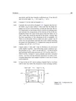
This complicated flow was analyzed by Karimi [8.39], who found that
Nu ≡
hd cos α
k
=
ρ
f
−ρ
g
ρ
f
h
fg
g(d cosα)
3
µk∆T
1/4
fn
d
D
,B
(8.68)
where B is a centripetal parameter:
B ≡
ρ
f
−ρ
g
ρ
f
c
p
∆T
h
fg
tan
2
α
Pr
and α is the helix angle (see Fig. 8.14). The function on the righthand side
of eqn. (8.68) was a complicated one that must be evaluated numerically.
Karimi’s result is plotted in Fig. 8.14.
Laminar–turbulent transition
The mass flow rate of condensate per unit width of film,
˙
m, is more com-
monly designated as Γ
c
(kg/m · s). Its calculation in eqn. (8.50) involved
substituting eqn. (8.48)in
˙
m or Γ
c
= ρ
f
δ
0
udy
Equation (8.48) gives u(y) independently of any geometric features. [The
geometry is characterized by δ(x).] Thus, the resulting equation for the
mass flow rate is still
Γ
c
=
ρ
f
ρ
f
−ρ
g
gδ
3
3µ
(8.50a)
This expression is valid for any location along any film, regardless of the
geometry of the body. The configuration will lead to variations of g(x)
and δ(x), but eqn. (8.50a) still applies.
§8.5 Film condensation 441
Figure 8.14 Fully developed film condensation heat transfer
on a helical reflux condenser [8.39].
It is useful to define a Reynolds number in terms of Γ
c
. This is easy
to do, because Γ
c
is equal to ρu
av
δ.
Re
c
=
Γ
c
µ
=
ρ
f
(ρ
f
−ρ
g
)gδ
3
3µ
2
(8.69)
It turns out that the Reynolds number dictates the onset of film insta-
bility, just as it dictates the instability of a b.l. or of a pipe flow.
11
When
Re
c
7, scallop-shaped ripples become visible on the condensate film.
When Re
c
reaches about 400, a full-scale laminar-to-turbulent transition
occurs.
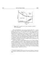
Gregorig, Kern, and Turek [8.40] reviewed many data for the film
condensation of water and added their own measurements. Figure 8.15
shows these data in comparison with Nusselt’s theory, eqn. (8.60). The
comparison is almost perfect up to Re
c
7. Then the data start yielding
somewhat higher heat transfer rates than the prediction. This is because
11
Two Reynolds numbers are defined for film condensation: Γ
c
/µ and 4Γ
c
/µ. The
latter one, which is simply four times as large as the one we use, is more common in
the American literature.
442 Natural convection in single-phase fluids and during film condensation §8.5
Figure 8.15 Film condensation on vertical plates. Data are for
water [8.40].
the ripples improve heat transfer—just a little at first and by about 20%
when the full laminar-to-turbulent transition occurs at Re
c
= 400.
Above Re
c
= 400, Nu
L
begins to rise with Re
c
. The Nusselt number
begins to exhibit an increasingly strong dependence on the Prandtl num-
ber in this turbulent regime. Therefore, one can use Fig. 8.15, directly as
a data correlation, to predict the heat transfer coefficient for steam con-
densating at 1 atm. But for other fluids with different Prandtl numbers,
one should consult [8.41]or[8.42].
Two final issues in natural convection film condensation
• Condensation in tube bundles. Nusselt showed that if n horizontal
tubes are arrayed over one another, and if the condensate leaves
each one and flows directly onto the one below it without splashing,
then
Nu
D
for n tubes
=
Nu
D
1 tube
n
1/4
(8.70)
This is a fairly optimistic extension of the theory, of course. In
addition, the effects of vapor shear stress on the condensate and of
pressure losses on the saturation temperature are often important
in tube bundles. These effects are discussed by Rose et al. [8.42]
and Marto [8.41].
Problems 443
• Condensation in the presence of noncondensable gases. When the
condensing vapor is mixed with noncondensable air, uncondensed
air must constantly diffuse away from the condensing film and va-
por must diffuse inward toward the film. This coupled diffusion
process can considerably slow condensation. The resulting h can
easily be cut by a factor of five if there is as little as 5% by mass
of air mixed into the steam. This effect was first analyzed in detail
by Sparrow and Lin [8.43]. More recent studies of this problem are
reviewed in [8.41, 8.42].
Problems
8.1 Show that Π
4
in the film condensation problem can properly
be interpreted as Pr Re
2
Ja.
8.2 A 20 cm high vertical plate is kept at 34
◦
Cina20
◦
C room.
Plot (to scale) δ and h vs. height and the actual temperature
and velocity vs. y at the top.
8.3 Redo the Squire-Eckert analysis, neglecting inertia, to get a
high-Pr approximation to Nu
x
. Compare your result with the
Squire-Eckert formula.
8.4 Assume a linear temperature profile and a simple triangular
velocity profile, as shown in Fig. 8.16, for natural convection
on a vertical isothermal plate. Derive Nu
x
= fn(Pr, Gr
x
), com-
pare your result with the Squire-Eckert result, and discuss the
comparison.
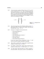
8.5 A horizontal cylindrical duct of diamond-shaped cross section
(Fig. 8.17) carries air at 35
◦
C. Since almost all thermal resis-
tance is in the natural convection b.l. on the outside, take T
w
to be approximately 35
◦
C. T
∞
= 25
◦
C. Estimate the heat loss
per meter of duct if the duct is uninsulated. [Q = 24.0W/m.]
8.6 The heat flux from a 3 m high electrically heated panel in a
wall is 75 W/m
2
in an 18
◦
C room. What is the average temper-
ature of the panel? What is the temperature at the top? at the
bottom?
444 Chapter 8: Natural convection in single-phase fluids and during film condensation
Figure 8.16 Configuration for Problem 8.4.
Figure 8.17 Configuration for
Problem 8.5.
8.7 Find pipe diameters and wall temperatures for which the film
condensation heat transfer coefficients given in Table 1.1 are
valid.
8.8 Consider Example 8.6. What value of wall temperature (if any),
or what height of the plate, would result in a laminar-to-turbulent
transition at the bottom in this example?
8.9 A plate spins, as shown in Fig. 8.18, in a vapor that rotates syn-
chronously with it. Neglect earth-normal gravity and calculate
Nu
L
as a result of film condensation.
8.10 A laminar liquid film of temperature T
sat
flows down a vertical
wall that is also at T
sat
. Flow is fully developed and the film
thickness is δ
o
. Along a particular horizontal line, the wall
temperature has a lower value, T
w
, and it is kept at that tem-
perature everywhere below that position. Call the line where
the wall temperature changes x = 0. If the whole system is
Problems 445
Figure 8.18 Configuration for
Problem 8.9.
immersed in saturated vapor of the flowing liquid, calculate
δ(x),Nu
x
, and Nu
L
, where x = L is the bottom edge of the
wall. (Neglect any transition behavior in the neighborhood of
x = 0.)
8.11 Prepare a table of formulas of the form
h(W/m
2
K) = C
[
∆T
◦
C/L m
]
1/4
for natural convection at normal gravity in air and in water
at T
∞
= 27
◦
C. Assume that T
w
is close to 27
◦
C. Your table
should include results for vertical plates, horizontal cylinders,
spheres, and possibly additional geometries. Do not include
your calculations.
8.12 For what value of Pr is the condition
∂
2
u
∂y
2
y=0
=
gβ(T
w
−T
∞
)
ν
satisfied exactly in the Squire-Eckert b.l. solution? [Pr = 2.86.]
8.13 The overall heat transfer coefficient on the side of a particular
house 10 m in height is 2.5 W/m
2
K, excluding exterior convec-
tion. It is a cold, still winter night with T
outside
=−30
◦
C and
T
inside air
= 25
◦
C. What is h on the outside of the house? Is
external convection laminar or turbulent?
8.14 Consider Example 8.2. The sheets are mild steel, 2 m long and
6 mm thick. The bath is basically water at 60
◦
C, and the sheets
446 Chapter 8: Natural convection in single-phase fluids and during film condensation
are put in it at 18
◦
C. (a) Plot the sheet temperature as a function
of time. (b) Approximate
h at ∆T =
[
(60 +18)/2 −18
]
◦
C and
plot the conventional exponential response on the same graph.
8.15 A vertical heater 0.15 m in height is immersed in water at 7
◦
C.
Plot
h against (T
w
− T
∞
)
1/4
, where T
w
is the heater tempera-
ture, in the range 0 <(T
w
− T
∞
)<100
◦
C. Comment on the
result. should the line be straight?
8.16 A77
◦
C vertical wall heats 27
◦
C air. Evaluate δ
top
/L, Ra
L
, and
L where the line in Fig. 8.3 ceases to be straight. Comment on
the implications of your results. [δ
top
/L 0.6.]
8.17 A horizontal 8 cm O.D. pipe carries steam at 150
◦
C through
a room at 17
◦
C. The pipe has a 1.5 cm layer of 85% magnesia
insulation on it. Evaluate the heat loss per meter of pipe. [Q =
97.3W/m.]
8.18 What heat rate (in W/m) must be supplied to a 0.01 mm hori-
zontal wire to keep it 30
◦
C above the 10
◦
C water around it?
8.19 A vertical run of copper tubing, 5 mm in diameter and 20 cm
long, carries condensation vapor at 60
◦
C through 27
◦
C air.
What is the total heat loss?
8.20 A body consists of two cones joined at their bases. The di-
ameter is 10 cm and the overall length of the joined cones is
25 cm. The axis of the body is vertical, and the body is kept
at 27
◦
Cin7
◦
C air. What is the rate of heat removal from the
body? [Q = 3.38 W.]
8.21 Consider the plate dealt with in Example 8.3. Plot
h as a func-
tion of the angle of inclination of the plate as the hot side is
tilted both upward and downward. Note that you must make
do with discontinuous formulas in different ranges of θ.
8.22 You have been asked to design a vertical wall panel heater,
1.5 m high, for a dwelling. What should the heat flux be if no
part of the wall should exceed 33
◦
C? How much heat will be
added to the room if the panel is7minwidth?
8.23 A 14 cm high vertical surface is heated by condensing steam
at 1 atm. If the wall is kept at 30
◦
C, how would the average
Problems 447
heat transfer coefficient change if ammonia, R22, methanol,
or acetone were used instead of steam to heat it? How would
the heat flux change? (Data for methanol and acetone must be
obtained from sources outside this book.)
8.24 A 1 cm diameter tube extends 27 cm horizontally through a
region of saturated steam at 1 atm. The outside of the tube can
be maintained at any temperature between 50
◦
C and 150
◦
C.
Plot the total heat transfer as a function of tube temperature.
8.25 A 2 m high vertical plate condenses steam at 1 atm. Below what
temperature will Nusselt’s prediction of
h be in error? Below
what temperature will the condensing film be turbulent?
8.26 A reflux condenser is made of copper tubing 0.8 cm in diameter
with a wall temperature of 30
◦
C. It condenses steam at 1 atm.
Find
h if α = 18
◦
and the coil diameter is 7 cm.
8.27 The coil diameter of a helical condenser is 5 cm and the tube
diameter is 5 mm. The condenser carries water at 15
◦
C and is
in a bath of saturated steam at 1 atm. Specify the number of
coils and a reasonable helix angle if 6 kg/hr of steam is to be
condensed. h
inside
= 600 W/m
2
K.
8.28 A schedule 40 type 304 stainless steam pipe with a 4 in. nom-
inal diameter carries saturated steam at 150 psia in a process-
ing plant. Calculate the heat loss per unit length of pipe if it is
bare and the surrounding air is still at 68
◦
F. How much would
this heat loss be reduced if the pipe were insulated witha1in.
layer of 85% magnesia insulation? [Q
saved
127 W/m.]
8.29 What is the maximum speed of air in the natural convection
b.l. in Example 8.1?
8.30 All of the uniform-T
w
, natural convection formulas for Nu take
the same form, within a constant, at high Pr and Ra. What is
that form? (Exclude any equation that includes turbulence.)
8.31 A large industrial process requires that water be heated by a
large horizontal cylinder using natural convection. The water
is at 27
◦
C. The diameter of the cylinder is 5 m, and it is kept at
67
◦
C. First, find h. Then suppose that D is increased to 10 m.
448 Chapter 8: Natural convection in single-phase fluids and during film condensation
What is the new h? Explain the similarity of these answers in
the turbulent natural convection regime.
8.32 A vertical jet of liquid of diameter d and moving at velocity u
∞
impinges on a horizontal disk rotating ω rad/s. There is no
heat transfer in the system. Develop an expression for δ(r ),
where r is the radial coordinate on the disk. Contrast the r
dependence of δ with that of a condensing film on a rotating
disk and explain the difference qualitatively.
8.33 We have seen that if properties are constant, h ∝ ∆T
1/4
in
natural convection. If we consider the variation of properties
as T
w
is increased over T
∞
, will h depend more or less strongly
on ∆T in air? in water?
8.34 A film of liquid falls along a vertical plate. It is initially satu-
rated and it is surrounded by saturated vapor. The film thick-
ness is δ
o
. If the wall temperature below a certain point on
the wall (call it x = 0) is raised to a value of T
w
, slightly above
T
sat
, derive expressions for δ(x),Nu
x
, and x
f
—the distance at
which the plate becomes dry. Calculate x
f
if the fluid is water
at 1 atm, if T
w
= 105
◦
C and δ
o
= 0.1 mm.
8.35 In a particular solar collector, dyed water runs down a vertical
plate in a laminar film with thickness δ
o
at the top. The sun’s
rays pass through parallel glass plates (see Section 10.6) and
deposit q
s
W/m
2
in the film. Assume the water to be saturated
at the inlet and the plate behind it to be insulated. Develop an
expression for δ(x) as the water evaporates. Develop an ex-
pression for the maximum length of wetted plate, and provide
a criterion for the laminar solution to be valid.
8.36 What heat removal flux can be achieved at the surface of a
horizontal 0.01 mm diameter electrical resistance wire in still
27
◦
C air if its melting point is 927
◦
C? Neglect radiation.
8.37 A 0.03 m O.D. vertical pipe, 3 m in length, carries refrigerant
through a 24
◦
C room. How much heat does it absorb from the
room if the pipe wall is at 10
◦
C?
8.38 A 1 cm O.D. tube at 50
◦
C runs horizontally in 20
◦
C air. What is
the critical radius of 85% magnesium insulation on the tube?
Problems 449
8.39 A 1 in. cube of ice is suspended in 20
◦
C air. Estimate the drip
rate in gm/min. (Neglect ∆T through the departing water film.
h
sf
= 333, 300 J/kg.)
8.40 A horizontal electrical resistance heater, 1 mm in diameter,
releases 100 W/m in water at 17
◦
C. What is the wire tempera-
ture?
8.41 Solve Problem 5.39 using the correct formula for the heat trans-
fer coefficient.
8.42 A red-hot vertical rod, 0.02 m in length and 0.005 m in diame-
ter, is used to shunt an electrical current in air at room temper-
ature. How much power can it dissipate if it melts at 1200
◦
C?
Note all assumptions and corrections. Include radiation using
F
rod-room
= 0.064.
8.43 A 0.25 mm diameter platinum wire, 0.2 m long, is to be held
horizontally at 1035
◦
C. It is black. How much electric power is
needed? Is it legitimate to treat it as a constant-wall-temperature
heater in calculating the convective part of the heat transfer?
The surroundings are at 20
◦
C and the surrounding room is
virtually black.
8.44 A vertical plate, 11.6 m long, condenses saturated steam at
1 atm. We want to be sure that the film stays laminar. What is
the lowest allowable plate temperature, and what is
q at this
temperature?
8.45 A straight horizontal fin exchanges heat by laminar natural
convection with the surrounding air.
a. Show that
d
2
θ
dξ
2
= m
2
L
2
θ
5/4
where m is based on h
o
≡ h(T = T
o
).
b. Develop an iterative numerical method to solve this equa-
tion for T(x = 0) = T
o
and an insulated tip. (Hint: lin-
earize the right side by writing it as (m
2
L
2
θ
1/4
)θ, and
evaluate the term in parenthesis at the previous iteration
step.)
450 Chapter 8: Natural convection in single-phase fluids and during film condensation
c. Solve the resulting difference equations for m
2
L
2
values
ranging from 10
−3
to 10
3
. Use Gauss elimination or the
tridiagonal algorithm. Express the results as η/η
o
where
η is the fin efficiency and η
o
is the efficiency that would
result if
h
o
were the uniform heat transfer coefficient over
the entire fin.
8.46 A 2.5 cm black sphere (F=1) is in radiation-convection equi-
librium with air at 20
◦
C. The surroundings are at 1000 K. What
is the temperature of the sphere?
8.47 Develop expressions for
h(D) and Nu
D
during condensation
on a vertical circular plate.
8.48 A cold copper plate is surrounded bya5mmhigh ridge which
forms a shallow container. It is surrounded by saturated water
vapor at 100
◦
C. Estimate the steady heat flux and the rate of
condensation.
a. When the plate is perfectly horizontal and filled to over-
flowing with condensate.
b. When the plate is in the vertical position.
c. Did you have to make any idealizations? Would they re-
sult in under- or over-estimation of the condensation?
8.49 A proposed design for a nuclear power plant uses molten lead
to remove heat from the reactor core. The heated lead is then
used to boil water that drives a steam turbine. Water at 5 atm
pressure (T
sat
= 152
◦
C) enters a heated section of a pipe at
60
◦
C with a mass flow rate of
˙
m = 2 kg/s. The pipe is stainless
steel (k
s
= 15 W/m·K) with a wall thickness of 12 mm and an
outside diameter of 6.2 cm. The outside surface of the pipe
is surrounded by an almost-stationary pool of molten lead at
477
◦
C.
a. At point where the liquid water has a bulk temperature
of T
b
= 80
◦
C, estimate the inside and outside wall tem-
peratures of the pipe, T
w
i
and T
w
o
, to within about 5
◦
C.
Neglect entry length and variable properties effects and
take β ≈ 0.000118 K
−1
for lead. Hint: Guess an outside
wall temperature above 370
◦
C when computing h for the
lead.
Problems 451
b. At what distance from the inlet will the inside wall of the
pipe reach T
sat
? What redesign may be needed?
8.50 A flat plate 10 cm long and 40 cm wide is inclined at 30
◦
from
the vertical. It is held at a uniform temperature of 250 K. Sat-
urated HCFC-22 vapor at 260 K condenses onto the plate. De-
termine the following:
a. The ratio h
fg
/h
fg
.
b. The average heat transfer coefficient,
h, and the rate at
which the plate must be cooled, Q (watts).
c. The film thickness, δ (µm), at the bottom of the plate, and
the plate’s rate of condensation in g/s.
8.51 One component in a particular automotive air-conditioning sys-
tem is a “receiver”, a small vertical cylindrical tank that con-
tains a pool of liquid refrigerant, HFC-134a, with vapor above
it. The receiver stores extra refrigerant for the system and
helps to regulate the pressure. The receiver is at equilibrium
with surroundings at 330 K.A5mmdiameter, spherical ther-
mistor inside the receiver monitors the liquid level. The ther-
mistor is a temperature-sensing resistor driven by a small elec-
tric current; it dissipates a power of 0.1 W. When the system
is fully charged with refrigerant, the thermistor sits below the
liquid surface. When refrigerant leaks from the system, the liq-
uid level drops and the thermistor eventually sits in vapor. The
thermistor is small compared to the receiver, and its power is
too low to affect the bulk temperature in the receiver.
a. If the system is fully charged, determine the temperature
of the thermistor.
b. If enough refrigerant has leaked that the thermistor sits in
vapor, find the thermistor’s temperature. Neglect thermal
radiation.
8.52 Ammonia vapor at 300 K and 1.062 MPa pressure condenses
onto the outside of a horizontal tube. The tube has an O.D. of
1.91 cm.
a. Suppose that the outside of the tube has a uniform tem-
perature of 290 K. Determine the average condensation
452 Chapter 8: Natural convection in single-phase fluids and during film condensation
heat transfer cofficient of the tube.
b. The tube is cooled by cold water flowing through it and
the thin wall of the copper tube offers negligible thermal
resistance. If the bulk temperature of the water is 275 K
at a location where the outside surface of the tube is at
290 K, what is the heat transfer coefficient inside the tube?
c. Using the heat transfer coefficients you just found, esti-
mate the largest wall thickness for which the thermal re-
sistance of the tube could be neglected. Discuss the varia-
tion the tube wall temperature around the circumference
and along the length of the tube.
8.53 An inclined plate in a piece of process equipment is tilted 30
◦
above the horizontal and is 20 cm long and 25 cm wide (in the
horizontal direction). The plate is held at 280 K by a stream of
liquid flowing past its bottom side; the liquid in turn is cooled
by a refrigeration system capable of removing 12 watts from
it. If the heat transfer from the plate to the stream exceeds 12
watts, the temperature of both the liquid and the plate will
begin to rise. The upper surface of the plate is in contact
with gaseous ammonia vapor at 300 K and a varying pressure.
An engineer suggests that any rise in the bulk temperature of
the liquid will signal that the pressure has exceeded a level of
about p
crit
= 551 kPa.
a. Explain why the gas’s pressure will affect the heat transfer
to the coolant.
b. Suppose that the pressure is 255.3 kPa. What is the heat
transfer (in watts) from gas to the plate, if the plate tem-
perature is T
w
= 280 K? Will the coolant temperature rise?
Data for ammonia are given in App. A.
c. Suppose that the pressure rises to 1062 kPa. What is the
heat transfer to the plate if the plate is still at T
w
= 280 K?
Will the coolant temperature rise?
References
[8.1] W. Nusselt. Das grundgesetz des wärmeüberganges. Gesund. Ing.,
38:872, 1915.
References 453
[8.2] C. J. Sanders and J. P. Holman. Franz Grashof and the Grashof
Number. Int. J. Heat Mass Transfer, 15:562–563, 1972.
[8.3] S. W. Churchill and H. H. S. Chu. Correlating equations for laminar
and turbulent free convection from a vertical plate. Int. J. Heat
Mass Transfer, 18:1323–1329, 1975.
[8.4] S. Goldstein, editor. Modern Developments in Fluid Mechanics, vol-
ume 2, chapter 14. Oxford University Press, New York, 1938.
[8.5] E. R. G. Eckert and R. M. Drake, Jr. Analysis of Heat and Mass
Transfer. Hemisphere Publishing Corp., Washington, D.C., 1987.
[8.6] A. Bejan and J. L. Lage. The Prandtl number effect on the transition
in natural convection along a vertical surface. J. Heat Transfer,
Trans. ASME, 112:787–790, 1990.
[8.7] E. M. Sparrow and J. L. Gregg. The variable fluid-property problem
in free convection. In J. P. Hartnett, editor, Recent Advances in Heat
and Mass Transfer, pages 353–371. McGraw-Hill Book Company,
New York, 1961.
[8.8] H. Barrow and T. L. Sitharamarao. The effect of variable β on free
convection. Brit. Chem. Eng., 16(8):704, 1971.
[8.9] W. Kraus. Messungen des Temperatur- und Geschwindigskeitsfeldes
bei freier Konvection. Verlag G. Braun, Karlsruhe, 1955. Chapter F.
[8.10] S. W. Churchill and H. H. S. Chu. Correlating equations for laminar
and turbulent free convection from a horizontal cylinder. Int. J.
Heat Mass Transfer, 18:1049–1053, 1975.
[8.11] T. Cebeci. Laminar-free-convective-heat transfer from the outer
surface of a vertical slender circular cylinder. In Proc. Fifth Intl.
Heat Transfer Conf., volume 3, pages 15–19. Tokyo, September
3–7 1974.
[8.12] T. Yuge. Experiments on heat transfer from spheres including
combined forced and natural convection. J. Heat Transfer, Trans.
ASME, Ser. C, 82(1):214, 1960.
[8.13] G. D. Raithby and K. G. T. Hollands. Natural convection. In W. M.
Rohsenow, J. P. Hartnett, and Y. I. Cho, editors, Handbook of Heat
Transfer, chapter 4. McGraw-Hill, New York, 3rd edition, 1998.
454 Chapter 8: Natural convection in single-phase fluids and during film condensation
[8.14] J. H. Lienhard. On the commonality of equations for natural con-
vection from immersed bodies. Int. J. Heat Mass Transfer, 16:2121,
1973.
[8.15] B. R. Rich. An investigation of heat transfer from an inclined flat
plate in free convection. Trans. ASME, 75:489–499, 1953.
[8.16] T. Fujii and H. Imura. Natural convection heat transfer from a
plate with arbitrary inclination. Int. J. Heat Mass Transfer, 15(4):
755–767, 1972.
[8.17] G. C. Vliet. Natural convection local heat transfer on constant heat
transfer inclined surface. J. Heat Transfer, Trans. ASME, Ser. C,
91:511–516, 1969.
[8.18] L. Pera and B. Gebhart. On the stability of natural convection
boundary layer flow over horizontal and slightly inclined surfaces.
Int. J. Heat Mass Transfer, 16(6):1147–1163, 1973.
[8.19] M. Al-Arabi and M. K. El-Riedy. Natural convection heat transfer
from isothermal horizontal plates of different shapes. Int. J. Heat
Mass Transfer, 19:1399–1404, 1976.
[8.20] L. Pera and B. Gebhart. Natural convection boundary layer flow
over horizontal and slightly inclined surfaces. Int. J. Heat Mass
Transfer, 16(6):1131–1147, 1973.
[8.21] B. Gebhart, Y. Jaluria, R. L. Mahajan, and B. Sammakia. Buoyancy-
Induced Flows and Transport. Hemisphere Publishing Corp., Wash-
ington, 1988.
[8.22] J. R. Lloyd and W. R. Moran. Natural convection adjacent to hor-
izontal surface of various planforms. J. Heat Transfer, Trans.
ASME, Ser. C, 96(4):443–447, 1974.
[8.23] A. M. Clausing and J. J. Berton. An experimental investigation of
natural convection from an isothermal horizontal plate. J. Heat
Transfer, Trans. ASME, 111(4):904–908, 1989.
[8.24] F. Restrepo and L. R. Glicksman. The effect of edge conditions on
natural convection heat transfer from a horizontal plates. Int. J.
Heat Mass Transfer, 17(1):135–142, 1974.
References 455
[8.25] D. W. Hatfield and D. K. Edwards. Edge and aspect ratio effects on
natural convection from the horizontal heated plate facing down-
wards. Int. J. Heat Mass Transfer, 24(6):1019–1024, 1981.
[8.26] V. Kadambi and R. M. Drake, Jr. Free convection heat transfer from
horizontal surfaces for prescribed variations in surface tempera-
ture and mass flow through the surface. Tech. Rept. Mech. Eng.
HT-1, Princeton Univ., June 30 1959.
[8.27] K. T. Yang. Natural convection in enclosures. In S. Kakaç, R. K.
Shah, and W. Aung, editors, Handbook of Single-Phase Convective
Heat Transfer, chapter 13. Wiley-Interscience, New York, 1987.
[8.28] I. Catton. Natural convection in enclosures. In Proc. Sixth Intl. Heat
Transfer Conf., volume 6, pages 13–31. Toronto, Aug. 7–11 1978.
[8.29] S. W. Churchill. A comprehensive correlating equation for laminar,
assisting, forced and free convection. AIChE J., 23(1):10–16, 1977.
[8.30] T. S. Chen and B. F. Armaly. Mixed convection in external flow. In
S. Kakaç, R. K. Shah, and W. Aung, editors, Handbook of Single-
Phase Convective Heat Transfer, chapter 14. Wiley-Interscience,
New York, 1987.
[8.31] W. Aung. Mixed convection in internal flow. In S. Kakaç, R. K. Shah,
and W. Aung, editors, Handbook of Single-Phase Convective Heat
Transfer, chapter 15. Wiley-Interscience, New York, 1987.
[8.32] V. K. Dhir. Quasi-steady laminar film condensation of steam on
copper spheres. J. Heat Transfer, Trans. ASME, Ser. C, 97(3):347–
351, 1975.
[8.33] V. K. Dhir and J. H. Lienhard. Laminar film condensation on plane
and axi-symmetric bodies in non-uniform gravity. J. Heat Transfer,
Trans. ASME, Ser. C, 93(1):97–100, 1971.
[8.34] W. Nusselt. Die oberflächenkondensation des wasserdampfes. Z.
Ver. Dtsch. Ing., 60:541 and 569, 1916.
[8.35] W. M. Rohsenow. Heat transfer and temperature distribution in
laminar-film condensation. Trans. ASME, 78:1645–1648, 1956.
[8.36] E. M. Sparrow and J. L. Gregg. A boundary-layer treatment of
laminar-film condensation. J. Heat Transfer, Trans. ASME, Ser. C,
81:13–18, 1959.
456 Chapter 8: Natural convection in single-phase fluids and during film condensation
[8.37] P. Sadasivan and J. H. Lienhard. Sensible heat correction in laminar
film boiling and condensation. J. Heat Transfer, Trans. ASME, 109:
545–547, 1987.
[8.38] E. M. Sparrow and J. L. Gregg. A theory of rotating condensation.
J. Heat Transfer, Trans. ASME, Ser. C, 81:113–120, 1959.
[8.39] A. Karimi. Laminar film condensation on helical reflux condensers
and related configurations. Int. J. Heat Mass Transfer, 20:1137–
1144, 1977.
[8.40] R. Gregorig, J. Kern, and K. Turek. Improved correlation of film
condensation data based on a more rigorous application of simi-
larity parameters. Wärme- und Stoffübertragung, 7:1–13, 1974.
[8.41] P. J. Marto. Condensation. In W. M. Rohsenow, J. P. Hartnett, and
Y. I. Cho, editors, Handbook of Heat Transfer, chapter 14. McGraw-
Hill, New York, 3rd edition, 1998.
[8.42] J. Rose, H. Uehara, S. Koyama, and T. Fujii. Film condensation. In
S. G. Kandlikar, M. Shoji, and V. K. Dhir, editors, Handbook of Phase
Change: Boiling and Condensation, chapter 19. Taylor & Francis,
Philadelphia, 1999.
[8.43] E. M. Sparrow and S. H. Lin. Condensation in the presence of a
non-condensible gas. J. Heat Transfer, Trans. ASME, Ser. C, 86:
430, 1963.
9. Heat transfer in boiling and
other phase-change
configurations
For a charm of powerful trouble,
like a Hell-broth boil and bubble
Cool it with a baboon’s blood,
then the charm is firm and good.
Macbeth, Wm. Shakespeare
“A watched pot never boils”—the water in a teakettle takes a long time
to get hot enough to boil because natural convection initially warms it
rather slowly. Once boiling begins, the water is heated the rest of the way
to the saturation point very quickly. Boiling is of interest to us because
it is remarkably effective in carrying heat from a heater into a liquid. The
heater in question might be a red-hot horseshoe quenched in a bucket or
the core of a nuclear reactor with coolant flowing through it. Our aim is to
learn enough about the boiling process to design systems that use boiling
for cooling. We begin by considering pool boiling—the boiling that occurs
when a stationary heater transfers heat to an otherwise stationary liquid.
9.1 Nukiyama’s experiment and the pool boiling curve
Hysteresis in the q vs. ∆T relation for pool boiling
In 1934, Nukiyama [9.1] did the experiment described in Fig. 9.1.He
boiled saturated water on a horizontal wire that functioned both as an
electric resistance heater and as a resistance thermometer. By calibrating
457
458 Heat transfer in boiling and other phase-change configurations §9.1
Figure 9.1 Nukiyama’s boiling hysteresis loop.
the resistance of a Nichrome wire as a function of temperature before the
experiment, he was able to obtain both the heat flux and the temperature
using the observed current and voltage. He found that, as he increased
the power input to the wire, the heat flux rose sharply but the tempera-
ture of the wire increased relatively little. Suddenly, at a particular high
value of the heat flux, the wire abruptly melted. Nukiyama then obtained
a platinum wire and tried again. This time the wire reached the same
§9.1 Nukiyama’s experiment and the pool boiling curve 459
limiting heat flux, but then it turned almost white-hot without melting.
As he reduced the power input to the white-hot wire, the temperature
dropped in a continuous way, as shown in Fig. 9.1, until the heat flux was
far below the value where the first temperature jump occurred. Then
the temperature dropped abruptly to the original q vs. ∆T = (T
wire
−
T
sat
) curve, as shown. Nukiyama suspected that the hysteresis would not
occur if ∆T could be specified as the independent controlled variable. He
conjectured that such an experiment would result in the connecting line
shown between the points where the temperatures jumped.
In 1937, Drew and Mueller [9.2] succeeded in making ∆T the inde-
pendent variable by boiling organic liquids outside a tube. Steam was
allowed to condense inside the tube at an elevated pressure. The steam
saturation temperature—and hence the tube-wall temperature—was var-
ied by controlling the steam pressure. This permitted them to obtain a
few scattered data that seemed to bear out Nukiyama’s conjecture. Mea-
surements of this kind are inherently hard to make accurately. For the
next forty years, the relatively few nucleate boiling data that people ob-
tained were usually—and sometimes imaginatively—interpreted as veri-
fying Nukiyama’s suggestion that this part of the boiling curve is contin-
uous.
Figure 9.2 is a completed boiling curve for saturated water at atmo-
spheric pressure on a particular flat horizontal heater. It displays the
behavior shown in Fig. 9.1, but it has been rotated to place the indepen-
dent variable, ∆T , on the abscissa. (We represent Nukiyama’s connecting
region as two unconnected extensions of the neighboring regions for rea-
sons that we explain subsequently.)
Modes of pool boiling
The boiling curve in Fig. 9.2 has been divided into five regimes of behav-
ior. These regimes, and the transitions that divide them, are discussed
next.
Natural convection. Water that is not in contact with its own vapor does
not boil at the so-called normal boiling point,
1
T
sat
. Instead, it continues
to rise in temperature until bubbles finally to begin to form. On conven-
tional machined metal surfaces, this occurs when the surface is a few
degrees above T
sat
. Below the bubble inception point, heat is removed
by natural convection, and it can be predicted by the methods laid out in
1
This notion might be new to some readers. It is explained in Section 9.2.
460 Heat transfer in boiling and other phase-change configurations §9.1
Figure 9.2 Typical boiling curve and
regimes of boiling for an unspecified
heater surface.
Chapter 8.
Nucleate boiling. The nucleate boiling regime embraces the two distinct
regimes that lie between bubble inception and Nukiyama’s first transition
point:
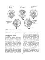
1. The region of isolated bubbles. In this range, bubbles rise from iso-
lated nucleation sites, more or less as they are sketched in Fig. 9.1.
As q and ∆T increase, more and more sites are activated. Fig-
ure 9.3a is a photograph of this regime as it appears on a horizontal
plate.
2. The region of slugs and columns. When the active sites become
very numerous, the bubbles start to merge into one another, and an
entirely different kind of vapor escape path comes into play. Vapor
formed at the surface merges immediately into jets that feed into
large overhead bubbles or “slugs” of vapor. This process is shown
as it occurs on a horizontal cylinder in Fig. 9.3b.
a. Isolated bubble regime—water.
b. Two views of transitional boiling in acetone on a 0.32 cm
diam. tube.
3.45 cm length of 0.0322 cm diam. wire
in methanol at 10 earth-normal gravities.
q=1.04×10
6
W/m
2
3.75 cm length of 0.164 cm diam. wire in benzene
at earth-normal gravity. q=0.35×10
6
W/m
2
c. Two views of the regime of slugs and columns.
d. Film boiling of acetone on a 22 gage wire at
earth-normal gravity. The true width of this
image is 3.48 cm.
Figure 9.3 Typical photographs of boiling in the four regimes identified in Fig. 9.2.
461
462 Heat transfer in boiling and other phase-change configurations §9.1
Peak heat flux. Clearly, it is very desirable to be able to operate heat
exchange equipment at the upper end of the region of slugs and columns.
Here the temperature difference is low while the heat flux is very high.
Heat transfer coefficients in this range are enormous. However, it is very
dangerous to run equipment near q
max
in systems for which q is the
independent variable (as in nuclear reactors). If q is raised beyond the
upper limit of the nucleate boiling regime, such a system will suffer a
sudden and damaging increase of temperature. This transition
2
is known
by a variety of names: the burnout point (although a complete burning
up or melting away does not always accompany it); the peak heat flux (a
modest descriptive term); the boiling crisis (a Russian term); the DNB,or
departure from nucleate boiling, and the CHF,orcritical heat flux (terms
more often used in flow boiling); and the first boiling transition (which
term ignores previous transitions). We designate the peak heat flux as
q
max
.
Transitional boiling regime. It is a curious fact that the heat flux ac-
tually diminishes with ∆T after q
max
is reached. In this regime the ef-
fectiveness of the vapor escape process becomes worse and worse. Fur-
thermore, the hot surface becomes completely blanketed in vapor and q
reaches a minimum heat flux which we call q
min
. Figure 9.3c shows two
typical instances of transitional boiling just beyond the peak heat flux.
Film boiling. Once a stable vapor blanket is established, q again in-
creases with increasing ∆T. The mechanics of the heat removal process
during film boiling, and the regular removal of bubbles, has a great deal
in common with film condensation, but the heat transfer coefficients are
much lower because heat must be conducted through a vapor film instead
of through a liquid film. We see an instance of film boiling in Fig. 9.3d.
Experiment 9.1
Set an open pan of cold tap water on your stove to boil. Observe the
following stages as you watch:
• At first nothing appears to happen; then you notice that numerous
small, stationary bubbles have formed over the bottom of the pan.
2
We defer a proper physical explanation of the transition to Section 9.3.
§9.1 Nukiyama’s experiment and the pool boiling curve 463
These bubbles have nothing to do with boiling—they contain air
that was driven out of solution as the temperature rose.
• Suddenly the pan will begin to “sing.” There will be a somewhat
high-pitched buzzing-humming sound as the first vapor bubbles
are triggered. They grow at the heated surface and condense very
suddenly when their tops encounter the still-cold water above them.
This cavitation collapse is accompanied by a small “ping” or “click,”
over and over, as the process is repeated at a fairly high frequency.
• As the temperature of the liquid bulk rises, the singing is increas-
ingly muted. You may then look in the pan and see a number
of points on the bottom where a feathery blur appears to be af-
fixed. These blurred images are bubble columns emanating scores
of bubbles per second. The bubbles in these columns condense
completely at some distance above the surface. Notice that the air
bubbles are all gradually being swept away.
• The “singing” finally gives way to a full rolling boil, accompanied
by a gentle burbling sound. Bubbles no longer condense but now
reach the surface, where they break.
• A full rolling-boil process, in which the liquid bulk is saturated, is
a kind of isolated-bubble process, as plotted in Fig. 9.2. No kitchen
stove supplies energy fast enough to boil water in the slugs-and-
columns regime. You might, therefore, reflect on the relative inten-
sity of the slugs-and-columns process.
Experiment 9.2
Repeat Experiment 9.1 with a glass beaker instead of a kitchen pan.
Place a strobe light, blinking about 6 to 10 times per second, behind the
beaker with a piece of frosted glass or tissue paper between it and the
beaker. You can now see the evolution of bubble columns from the first
singing mode up to the rolling boil. You will also be able to see natural
convection in the refraction of the light before boiling begins.