[Psychology] Mechanical Assemblies Phần 7 ppt
Bạn đang xem bản rút gọn của tài liệu. Xem và tải ngay bản đầy đủ của tài liệu tại đây (6.09 MB, 58 trang )
328
13
HOW TO
ANALYZE EXISTING PRODUCTS
IN
DETAIL
•
Classify
the
items
as
follows:
i.
Main
function
carriers (carriers
of
important
forces,
motions, material
flows,
energy,
or in-
formation
2
;
conveyors
or
blockers
of
fields
like
electricity
or
heat;
locators
of
main
geometric
relationships)
ii.
Functional supports (user adjustments, user
ac-
cess, seals, lubricants, vents)
iii.
Geometric supports (brackets, barriers, shields)
iv.
Ergonomic supports (handles,
labels,
safety
items, indicators, warnings,
finger
guards)
v.
Production supports (test points, adjustment
points, measurement points,
fixturing or
gripping
surfaces)
vi.
Fasteners
(reversible,
irreversible)
•
Keep track
of
dependencies between things, such
as
alignments, subassembly boundaries,
or
places
where several things must line
up for
proper
function.
•
Note
any
cases where
the
product
has
multiple states
such
as
on/off,
locked/unlocked,
forward/reverse,
low-speed/high-speed,
and so on.
These
may be as-
sociated with parts that have
different
positions
or
mating
configurations
in the
different
states.
•
Keep
track
of all the
tools
needed,
all the
difficult
steps,
and any
special care
or
consideration needed.
Take
the
product apart
in
stages
and
ensure
at
each
stage that
it can be
reassembled
from
that
stage.
3
This
is
especially important
any
time
the
disassembler suspects
that
energy
may be
stored
in the
product. Hidden springs
are a
typical hazard; they
can go flying
away unexpectedly
and
may
never
be
found
again.
It is a
good
idea
to
separate
items partially, peek inside
if the
items
are
covers,
and try
to see if any
surprises
are in
store.
Look
for
clues
as to how it
comes apart. These
in-
clude parting lines
and the
direction
from
which fasteners
appear
to
insert. This will give
an
indication
of the
prod-
uct's architecture
and
overall design. Some products
are
obviously
contained within
an
outer housing which must
be
separated before internal parts
can be
seen
and
further
disassembled.
A
typical example
is an
electric
screwdriver.
Other products
do not
have this kind
of
architecture.
An
example
is
typical clock
or
watch works,
in
which
the top
and
bottom plates together provide location
and
alignment
for
many other parts.
As
soon
as one
plate
is
removed,
the
other parts
can
spontaneously
separate
from
each other.
A
third architecture
is
represented
by a car
engine block.
Typically
over
two
hundred parts
are
fastened
to its
outside
by
screws. Inside
the
block
and
head
are an
additional hun-
dred
or so
parts.
But
there
is no
outer cover which, when
removed,
reveals
the
remaining parts.
You
may
encounter parts
or
features whose purpose
cannot
be
explained.
We
call these "mystery features."
Features cost money
and are
rarely without purpose. Fig-
uring
them
out can be
educational. Possibly they
are of
use
on a
different
model
of the
product
and are put
there
via
a
parallel production
process
4
like molding.
It may be
cheaper
to
make
all the
parts
the
same than
to
make
a
sepa-
rate mold
for
each version.
On the
other hand,
the
mystery
feature
may
perform
an
important
function,
in
which case
the
analyst must determine what
it is.
Examples
are in
Section 13.C.4.
It
is
always
useful
to
have
a
magnifying
glass
handy
so
that
small details
on
parts
can be
observed. These include
surface
finish
quality, molding methods such
as
location
of
risers,
dates
or
location
of
manufacture,
and so on. In
a
product made
in
China
for
export,
we
found
assembly
instructions
in
Chinese molded into
the
insides
of
several
parts.
One can
also assess fabrication quality, such
as the
quality
of
solder joints.
13.B.
HOW TO
IDENTIFY
THE
ASSEMBLY
ISSUES
IN A
PRODUCT
Analysis
of a
product
from
the
viewpoint
of
assembly
re-
quires addressing many levels
of
detail. Here
we
empha-
size
the
lower levels,
but it is
important
to
remember that
as
2
These
functional
categories
were developed
in
[Pahl
and
Beitz].
3
This
is
analogous
to
"woodsmanship"
advice
to
look over one's
shoulder
periodically
while hiking
so
that
the way
back
will
look
familiar.
a
whole,
we
recommend
a
top-down approach, beginning
with
functional,
physical,
and
economic requirements,
and
then
proceeding
to
deal with
the
supporting details,
as
out-
lined
in
Chapter
12.
Top-down
is an
admirable goal,
but
4
A
parallel process creates
all the
part's features
at
once.
A
serial
process,
such
as
machining,
creates
the
features
one or a few at a
time.
13.B.
HOW TO
IDENTIFY
THE
ASSEMBLY ISSUES
IN A
PRODUCT
329
it
is not
always possible
or
even feasible.
In
many
cases,
one is
confronted with
an
existing design which
is
being
modestly modified.
In
fact,
"reuse"
of
previous parts
or
subassemblies
is
becoming
mandated
at
many
companies
in
the
interest
of
saving development
and
verification time
and
cost. Therefore,
we
begin
by
listing
the
steps
for
ana-
lyzing
a
product
in
detail:
•
Understand each part,
its
material, shape, surface
fin-
ish,
and so on.
•
Understand each assembly step
in
detail, including
all
necessary motions, intermediate states, in-process
and final
checks
for
completeness.
•
Identify
high-risk areas.
•
Identify necessary experiments
to
reduce uncertainty
about
any
step.
•
Recommend local design improvements.
It
is
important that these analyses
be
performed
by a
group
of
people working together
who
collectively have
the
skills
and
background
to
consider
a
wide range
of
tech-
nical
and
nontechnical
issues.
This
will
ensure that
the
parts
are
subject
to a
broadly based
set of
eyes
and
criteria
and
that interactions between parts
and
among opportu-
nities
for
improvement
are
recognized. This
may
well
be
the
only time when
all the
parts
are
considered
at the
same
time
for the
same reason. This important opportunity
for
integration
should
not be
missed.
Analyzing
an
existing product requires taking
it
apart.
Pointers
for
doing this
and for
looking
carefully
are
given
in
Section
13.A.
We now
take
up
each
of
these steps.
13.B.1.
Understand
Each
Part
Assembly analysts have
the
responsibility
for
understand-
ing not
only what each part
is but
also what
it
does.
If
its
function
is not
understood, then redesign recommen-
dations
may
make
the
part incapable
of
performing
its
function.
On the
other hand, some recommendations listed
below seek
to
combine parts. Again,
the
required
function
must
never
be
compromised.
This analysis must include understanding
how
each
part
is
made,
why its
material
was
chosen, what surface
finish
and
tolerances
it
has,
and how
these might influence
how
it
will
be
assembled.
As
discussed
in
Chapters
10
and
11,
size, shape, surface
finish (as it
influences
friction)
and
clearance
to a
mating part heavily
influence
success
or
failure
during part mating.
To
help
in
this process,
one
may
make drawings
of the
parts either
on
paper
or in a
computer. These drawings
are
useful
in
step
2
where each
assembly action
is
studied.
This
is the
time
to
recognize
and
understand mystery
features.
13.B.2.
Understand
Each
Assembly
Step
In
order
to
begin this step,
it is
necessary
to
have either
the
parts
or the
drawings made
in
step
1.
Each part mate
should
be
studied
in
detail. Each surface
on a
part that will
or
could contact
a
surface
on a
mating part should
be
identi-
fied.
Possible mismated states should
be
noted, along with
possible
ways that
the
parts could
become
mismated.
Two
such
states,
called
wedging
and
jamming
respectively,
are
analyzed
in
detail
in
Chapter
10.
Find
all the
places
on
each part where
it
might
be
gripped
or fixtured.
Keep
in
mind
that only
one or a few of
these feasible
places
will
actually
be
possible
to
use,
for a
variety
of
reasons.
First, depending
on the
assembly sequence,
a
candi-
date grip
or fixture
location could
be
obscured
or in use
already
as a
mating feature
to
another
part.
Second,
and
much
harder
to see
just
by
looking
at the
parts,
the
rela-
tionship
between
the
gripped point
and the
mating feature
on
the
part
may not be
adequately toleranced.
The
result
of
this
is
that
if
machine
or
robot assembly
is
being used,
the
mating
point
may not be in the
correct
location
in
space
at
the
moment
of
assembly even
if the
gripped point
is. The
influence
of
tolerances
and the
relationships between fea-
tures
within
and
between parts
are
discussed
in
Chapters
2
through
6.
Rehearse
or
imagine each assembly step occurring
be-
fore
your eyes.
"Watch"
the
parts move through
space
and
meet each other.
Try to
anticipate
how
things could
go
wrong, including collisions with neighboring parts
or
between parts
and
tools, grippers,
or fixtures. One may
be
able
to use
simulation software
to aid
this part
of the
analysis.
This analysis
may
turn
up
many situations where
parts
could damage each other.
For
example,
soft
items like
seals could
be cut by
sharp metal edges.
All
such edges
should
be
found
and
targeted
for
softening
or
chamfer-
ing.
Another example
is a
situation where
a
part could
be
assembled
the
wrong way.
It
is
often
surprising
how
much
one can
learn
doing
one of
these analyses,
and how
often
an
outsider
can
learn things that
the
product's designers
or
current
as-
semblers
do not
know.
As
noted
in the
Preface,
the
author
spent
many years with colleagues analyzing commercial
330
13
HOW TO
ANALYZE
EXISTING
PRODUCTS
IN
DETAIL
products
for
assembly.
We
learned repeatedly that people
do not
understand their
own
processes. Once
we
hired
a
new
employee
who
accompanied
us on his first
visit
to a
client whose product
we
were assessing
for
possible robot
assembly.
We
scheduled
a
one-hour meeting with
the
line
supervisor
to
learn
in
detail
about
the
existing manual
assembly processes.
The
meeting quickly extended into
three hours
and was not
completed
before
we had to de-
part
for the
airport.
We
found
that
in
many cases
a
step
in
the
"official computer
printout"
of the
process proved
impossible.
For
example,
one
part could
not be
assem-
bled
in the
official
sequence
because
it
would obscure
an
adjusting
screw
on a
previously assembled part.
As we
identified
each such disconnect
in the
process,
the
line
supervisor became more concerned
and
perplexed, being
reduced
finally to
making
a
long list
of
action items
to
check
the
next time
he
visited
the
line.
As we
were
ap-
proaching
the car in the
parking lot, well
out of
earshot
of
our
host,
our new
colleague asked,
"Is it
always like
this?"
We
answered
in
unison: "Yes, it's always like
this!"
13.B.3.
Identify
High-Risk
Areas
High-risk areas
are
those parts
of the
process that could
go
wrong,
cost
a
lot, damage parts, injure employees,
or
cause
an
assembly station, whether manual
or
mechanized,
to
fail
too
often.
First priority goes
to
identifying
"showstoppers,"
those
events that stop
a
machine
from
working,
or
which vio-
late regulatory
or
safety
standards. Such events
get
their
name
from
the
high likelihood that there
is no
solution.
One
example involved
the
need
to
apply
a
small amount
of
a
low-viscosity adhesive
to
parts that would eventually
spin
at a
high rate.
The
slightest excess
of
this material
would
be
instantly sprayed
all
over
the
inside
of the as-
sembly, ruining
it. A
redesign
was
proposed that provided
a
well
in
which
any
excess would
be
trapped.
Another
tipoff
that
a
step
has
high risk
is
that only
one
person
on the
line
can
perform
it.
Once
we
observed
a
line
that
had two
such steps, each done
by a
different
person.
"Don't
let
those
two
carpool!"
one of us
said. This kind
of
situation leads naturally
to the
conclusion discussed
at
length
in
Chapter
1,
namely that
if we
can't explain
a
task
to
another person,
we
won't
be
able
to
explain
it to a
machine.
Any
step where part damage
is
likely
is
automatically
high risk.
In one
product
we
studied,
the
parts were
ex-
tremely
fragile
ceramic insulators, shipped
to the
line
immersed
in
sawdust. Clearly
the
objective
of the
assem-
blers
was to
keep
from
breaking them, well above
any
requirement
to
assemble them, since they were very
ex-
pensive. Similarly,
for
some parts, even
miniscule
surface
contamination
by
particles
or
chemicals will ruin them.
Semiconductor
wafers
are a
familiar example.
An
8-inch-
diameter
wafer
with 100+ Pentium chips
on it
represents
$30,000
or
more value
at
retail,
and
particles
even smaller
than
1
/zm
will
ruin
a
chip.
A
less
obvious
risk
area
is one
where
no
available
as-
sembly sequence
is
suitable, although
an
attractive
one is
just
out of
reach
for
some
reason.
Perhaps
a
small
redesign
will
make that attractive sequence feasible,
but
unless that
redesign
is
accepted,
the
process contains
risk. In one
case,
we
recommended
adding
a
part
to a
subassembly
so
that
it
became stable
and
could
be
inserted
as a
unit
without com-
plex tooling. Note that this violates
the
desire expressed
above
and in
Chapter
15 to
reduce part count.
Still less obvious
but
very important
for
eventual mech-
anization
of an
assembly process
is risk
caused
by
variable
process time.
An
example
is
calibration, which
can
take
more
or
less time depending
on how far off the
desired
setting
the
assembly
is
when
it
arrives
at the
calibration
station.
In one
case, Denso eliminated most
of the
task
time uncertainty
by
correlating
the final
calibrated
setting
of
thirty
or so
previous assemblies with
the
initial error
observed prior
to
starting calibration.
The first
step
in the
calibration
was
then selected
from
the
correlation table,
and
nearly every calibration
was finished in two
steps,
a
predictable time.
13.B.4.
Identify
Necessary
Experiments
Experiments
are
costly
and
time-consuming
and
thus
should
be
performed only when really necessary. Sim-
ulations
are
becoming increasingly
realistic
and
should
be
tried
first.
Nevertheless,
no
simulation
can
anticipate
every problem,
and
some problems
are
notorious
for
aris-
ing
as a
result
of
something that
is on the
parts
but not
in
the
design. Examples include small burrs, sharp edges,
springy
parts with minor residual shape distortion,
or
sur-
face
contamination
from
cleaning processes.
Experiments
can be
directed
at
confirming either tech-
nical
or
economic
feasibility.
While
the
former
is the
most
obvious
application,
the
latter
can be
tested
by finding out
how
long
it
really takes
to do a
task without making
a
lot of
errors,
or how
much things really cost
to
make
or
buy.
Sometimes,
as
indicated
in
Chapter
18, it is
only
13.C.
EXAMPLES
331
the
product
of
time
and
cost that matters,
and a
slower
but
cheaper
process
may be the
economic
equivalent
of
a
faster
but
more expensive one. Sometimes
the
slower
alternative
is
less complex
and
more reliable, tipping
the
balance
in its
favor.
In
case
of
technical feasibility evaluation,
it is
essential
to
identify
at the
outset what
are the
criteria
for
successful
assembly
in
terms
of
time, error rate, tolerable forces
ex-
erted
on the
parts,
and so on. Any
successful
process will
contain designed-in poka-yoke that prevents
the
standard
errors and,
if
possible, signals
if any of
them occurs.
Finally,
a
real physical experiment reveals potential
un-
documented sources
of
trouble. These
can
arise
from
un-
documented features
on
parts
or
unexpected behaviors
of
people
or
equipment. Only
by
trying them
out can
such
problems
be
revealed.
An
example
of
this
was
cited
in
Chapter
1,
namely that
of the
ladies
who
were
"cleaning"
fiber.
13.B.5.
Recommend
Local
Design Improvements
All
the
above
analyses
and
studies will generate sugges-
tions
for
improvements. These
can
range
from
adding
or
removing
a
detail
from
a
part
to
adding
or
removing
parts.
The
highest priority items address
the
high risk areas,
es-
pecially
the
showstoppers. Others improve technical
or
economic feasibility. Improvements
of
this kind address
distinctly
local issues
and are
unlikely
to
affect
strategic
matters such
as how
many
different
product styles
can be
accommodated
or
what
the
platform strategy
for a
product
family
will
be.
These
strategic issues
are the
province
of
assembly
in the
large.
The
next section gives several examples
of
product
analysis:
an
electric
drill,
a toy
(surprisingly complex),
a
camera,
and
some mystery features.
13.C. EXAMPLES
13.C.1.
Electric
Drill
5
An
MIT
student group took apart
and
carefully
analyzed
an
electric drill. They listed every part, noted
its
material,
measured
key
dimensions
at
places where they joined each
other,
and
enumerated
the
motions needed
to put
them
to-
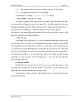
gether. Figure
13-1
is a
photo
of the
drill with
the top
cover
off.
Figure
13-2
is an
exploded view. Table
13-1
is the
parts
list.
Table 13-2 lists several part mate dimensions.
The
next
few
paragraphs detail
the
assembly steps, not-
ing
the
gross motions
of
part movement
and fine
motions
of
part mating.
13.C.1.a.
Transmission Subassembly
IB.C.l.a.l.
Step
1.
This step inserts
a
small
shaft
(14)
and
a
pinion gear
(13)
into
the
middle mount
(12)
containing
several bearings.
See
Figure
13-3.
Features
on
parts where
assemblers
can
grip
are
cylindrical surfaces
and
gear teeth.
The
orientation
of the
assembly
is
from
up to
downward
against gravity. Jamming
can
occur
in the
peg-hole
assem-
bly.
This process needs
two
hands, because
the
assembler
should hold
the
gear
to fit the
shaft
to the
hole.
If we use
5
This
material
was
prepared
by MIT
students Young
J.
Jang, Jin-
Pyong Chung,
and
Nader Sabbaghian.
The
drill
is
also
discussed
in
Chapter
14.
FIGURE
13-1.
Electric
Drill.
a fixture to fix the
mounting plate,
it
will mate
the
plate's
cylindrical surface.
13.C.l.a.2.
Step
2.
This
step
adds
the
drill
head
sub-
assembly
(15)
to the
subassembly built
in
step
1.
The
drill
head's
shaft
mates
to
plate
(12)
and its
gear
mates
to the
pinion
(13).
See
Figure 13-4. Features
on
parts where
the
assembler
can
grip
are
cylindrical
surfaces.
The
subassem-
bly
made
in
step
1 is
very loose, because
no
fasteners
are
used.
So, it can
fall
apart
if we are not
careful about holding
it
with
the
gear
facing
upright.
If we
think about automatic
332
13
HOW TO
ANALYZE
EXISTING
PRODUCTS
IN
DETAIL
TABLE
13-1.
Parts
List
for
Electric
Drill
in
Figure
13-2
TABLE
13-2.
Part
Dimensions
Related
to
Joints
Between
Parts
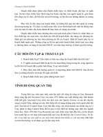
FIGURE
13-2.
Exploded
View
of
Sears
Craftsman
Drill.
assembly,
the
gear
teeth
between
the two
gears
can
collide
if
not
properly
positioned
during
assembly.
13.
C.
l.a.3.
Step
3.
This
step
joins
the
rotor
(10)
and
drill
head
mount
(16)
to the
subassembly
made
in
step
2. To
Note:
The
clearance
ratio
is
defined
as the
clearance
between
two
parts
at a
feature
where
they
join,
divided
by the
size
of the
feature.
For
example,
in a
pin-hole
joint,
the
clearance
ratio
is the
diametral
clearance
divided
by the
diameter.
This
concept
is
discussed
in
Chapter
10,
where
its
influence
on
ease
of
assembly
is
quantified.
make
this
happen
most
easily,
the
subassembly
from
step
2
should
be
reoriented
in the
horizontal
direction
(see Fig-
ure
13-5).
This
is due to the
fact
that
it is not
easy
to
assemble
the
rotor
shaft
vertically
into
the
mounting
plate
while
holding
the
washers
(8 and 9) and
journal
bearing
(17)
at the
other
end.
Even
when
it is
reoriented,
it is
diffi-
cult
to
hold
everything
without
any
gripper
or
fixture.
So,
Part
Number
la
Ib
2
3
5a
5b
6a
6b
7a
7b
8
9
10
11
12
13
14
15
16
17
18
Part
Name
Top
plastic casing
Bottom plastic casing
Stator
Controller/switch
Power cord
Left
brush housing
Right
brush housing
Left
spring
Right
spring
Left
brush
Right
brush
Thin washer
Thick washer
Rotor
Spring washer
Middle mount
Pinion
Gear
Gear
shaft
Drill
head
and
chuck
Drill head mount
Rear bearing
Screws
(8)
Fart
Description
Plastic casing placed
on top of the
bottom casing
after
the
insertion
of
drill subassemblies.
Plastic casing used
to
house
the
drill subassemblies.
Houses
the
rotor
and
connected
to
electromechanical controller
and
switch.
Variable-speed plastic switch
with
electrical connectors
to
power cord
and
stator.
Connected
to
switch, provides connection
to
120-V,
60-Hz
AC
power.
Brass component connected
to
wiring
from
switch, used
to
hold
a
brush
and
spring.
Same
as
left
brush housing (5a).
Spring mechanism used
for the
placement
of the
brush
in the
casing.
Same
as
left
spring (6a).
Rectangular
block
of
carbon interfacing
with
the
motor
and
switch.
Same
as
left
brush (7a).
Plastic washer placed
at the
back
end of the
rotor.
It is
used
to
prevent lateral movement
of the
rotor.
Same
as 8.
Possibly selected
from
several available thicknesses.
Rotor component equipped with radial
fan
blades
and
front
gear.
Metallic washer used
to
facilitate
the
insertion
of the
subassembly into
the
plastic casing
and
keep
the
rotor
from
rattling laterally.
Used
as an
interface between
the
back part
of the
assembly (rotor)
and the
front
part (drill head).
Used
for the
transfer
of
motion
from
the
rotor
to the
drill head
via the
middle mount.
Used
to
connect
the
pinion gear
to the
middle mount.
Equipped
with
gear which interfaces with part
13.
Its
back
shaft
is
housed
in the
middle mount
and is
equipped with
a
small thrust bearing.
Semicircular
structure supporting
the
drill head, placed inside
the
bottom casing; supports gear
shaft.
Made
of
powder metal bronze impregnated
with
lubricant.
A
locking mechanism prevents
it
from
rotating
once placed
in the
plastic casing.
Fasten
top and
bottom casings together.
Mating
Parts
8 to 10
9 to 10
17
to 10
11
to 10
12
to 10
12
to 15
12
to 14
13
to 14
16
to 15
Clearance
(inches)
0.013
0.013
0.008
0.033
0.008
0.001
0.005
0.005
0.01
Clearance
Ratio
0.040
0.040
0.025
0.096
0.025
0.003
0.040
0.040
0.016
4
13.C. EXAMPLES
333
the
assembler must
use his or her
whole palm
and
fingers
to
assemble these parts. This could present
a
challenge
for
the
assembler
and
potentially increase
the
assembly
time.
If we use a
gripper,
it
will
be
easier
to
perform this
step. However, this means introducing
an
additional step
in
the
process, that
of
attaching
the
gripper
to the
gear-train
subassembly.
FIGURE
13-3.
First
Step
in
Assembling
the
Transmission
Subassembly
of the
Drill.
FIGURE
13-4.
Second
Step
in
Assembling
the
Transmis-
sion Subassembly
of the
Drill.
A
little grease might
be
used
to
hold
the
bearing onto
the
end
of the
shaft
temporarily,
but
this will clog
the
bearing
and
keep
the
impregnated
oil
from
emerging later.
An-
other possible solution
is to put the
bearing
in the
bottom
casing instead
of
onto
the
shaft.
But
once this
is
done,
it
is
impossible
to
mate
the
shaft
with
it. In any
case,
this
does
not
solve
the
problem
of
keeping
the
washers
on the
shaft.
13.C.1.b.
Power Generation Subassembly
The
power subassembly (parts 2-7) consists
of the
motor,
switch,
and
wires, plus brushes
and
their
springs (see Fig-
ure
13-6).
Except
for the
brushes,
all
joints
in
this unit
are
pre-assembled
and
fastened.
So, it is
easy
to
handle.
But
the
lengths
of the
wires
are not
optimized
and are
unnec-
essarily long.
It is
also very hard
to
insert
the
springs that
hold
the
brushes
in the
rectangular holes. This consists
of a
spring-locking mechanism that keeps
the
brushes tightly
inserted
in the
brush holders,
yet
allows them
to be re-
leased once assembled
to the
armature
and
pressed against
FIGURE
13-6. Assembly
of the
Power Generation Sub-
assembly.
FIGURE
13-5.
Third
Step
in
Assembling
the
Transmission Subassembly
of the
Drill.
334
13
HOW TO
ANALYZE EXISTING PRODUCTS
IN
DETAIL
FIGURE
13-7. Photos
of
Brush Holder, Spring,
and
Brush Subassembly.
(a)
Brush
and
holder partially inserted into
the
casing. (b,c) Detailed views
of
brush
and
holder. This clever subassembly
has two
states. Before being inserted into
the
cas-
ing,
it is
cocked:
The
coil portion
of the
spring
is
placed
on a pin on the
holder with
its
rear
arm
inside
and its
front
arm
outside.
The
brush
is
placed
in the
holder,
and the
front
arm is
carefully stretched
and
placed
on the
face
of the
brush
as
shown
in
the
detail
photos.
This pushes
the
brush
back
inside
the
holder.
The
photo
above shows
the
cocked subassembly after
it has
been
inserted part
way
into
its
final position
in the
bottom case. (Normally,
the
rotor would
be
installed before this step,
but
it
has
been removed
to
permit
the
photo
to
show
the
situation.) When
the
subassembly
is
inserted
all the
way,
the
front post
dislodges
the
front
arm of the
spring
from
the
face
of the
brush.
The
front
arm
snaps
back until
it
rests
on the
hook.
The
rear
arm
of the
spring then
can
push
the
brush forward into contact with
the
rotor. When
the
drill
was
first disassembled,
the
hook
was a
mystery feature. (Photos
by
Karl Whitney.)
it.
6
These parts
are
shown
in
Figure
13-7
and
Figure 13-8.
They
can be
assembled
at
this stage,
or
this step
can be
delayed until
after
the
power subassembly
and
transmis-
sion subassembly have
been
mated
to the
bottom casing
during
final
assembly.
13.C.1.C.
Final Assembly
To
assemble
the
entire
unit,
the
armature
of the
trans-
mission sub-assembly should
be
inside
the
stator
of the
power generation subassembly (see Figure 13-9).
The
joints between
the
casings
and the
parts
of
this subassem-
bly
are
very tight
fitting in
order
to
prevent rattling
and
wear
while transmitting high torque.
It is
very
difficult
to
hold these
two
subassemblies together
and
perform
the
6
Getting
spring-loaded brushes into operating position
in
contact
with
commutators
is a
generic problem
in
motor
assembly.
There
are
many
clever
solutions,
most
of
which
require
that
the
rotor
be in
place
first and the
springs activated later.
gross motion
to the
plastic casing.
In the
difficult
fine mo-
tion
between
the
plastic casing
and two
subassemblies,
many
parts must assemble simultaneously into tight clear-
ances.
The
parts
can be
tilted
relative
to
each
other
during
the
assembly process, because
of the
clearances between
shafts
and
holes.
This
can
keep
the
middle
mount,
drill
head mount,
and
drill head
from
assembling
to the
bottom
casing.
During
the
assembly process, manual feedback control
in
fine
motion
is
needed
to
adjust
the
angles
of
shafts
and
the
middle mount horizontally
and
vertically.
The
transmission
and
power generation subassemblies
are
only
loosely
joined,
and it is
therefore
necessary
for the as-
sembler
to
grip
the
entire subassembly
in two
locations
(one
on the
transmission
and one on the
power generation
part)
to
ensure that
the
overall subassembly maintains
its
proper alignment
for
insertion into
the
plastic casing.
The
alignment
and
free
motion
of the
gears
and the
clearance
between
the
armature
and the
stator should
be
checked
be-
fore
the
closing
of the top
plastic
casing.
The
joint
between
13.C.
EXAMPLES
335
FIGURE
13-8.
Illustrating
the Two
States
of the
Brush-Holder
Sub-
assembly.
FIGURE
13-9.
Final Assembly
of the
Drill.
middle mount
and the
drill-head's
shaft
is the one
most
likely
to jam
during this
final
step.
After
these parts
are
installed,
the
brushes
are
installed
into their housings
and the
springs cocked,
if
this
was not
done before. Then each brush holder
is
pressed into
its
in the
bottom casing, releasing
the
brush. This
is
an
awkward motion.
If it is
done incorrectly,
the
brush
could
fly out
under spring action.
The
wires must
be
routed carefully
and
tucked away
from
the
joint between
the top and
bottom casings. This,
too,
is an
awkward
step.
7
Eight screws
are
used
as
fasteners
to
assemble
the two
housings.
13.C.2.
Child's
Toy
Let us
examine another example,
a
low-cost toy.
The
elec-
tric
"robot
dog,"
illustrated
in
Figure
13-10,
is
operated
by
a
small control
box
containing
two
batteries
and two
buttons.
Pushing
one
button causes
the dog to
walk, while
pushing
the
other
causes
the
head
to bob and the dog to
emit
a
squeak.
The
dog's
tail wags,
its
ears swing,
and
lights
in its
head
and
tail blink while
it is
walking.
It
costs
$5.99
retail
and is
made
in
China.
It is one of a
family
of
four
similar toys with similar
functionality
and the
same
price
and
target market.
7
The
author
had an
older drill whose casings were metal.
One day
he
felt
a
tingling
in his
hands while using this tool. Upon opening
it,
he
found
one of the
wires crushed between
the
casing halves
and the
conductor exposed, creating
an
electrical path
to his
hands. Newer
tools must obey double insulation regulations,
so
this hazard
will
not
occur.
336
13 HOW TO
ANALYZE EXISTING PRODUCTS
IN
DETAIL
FIGURE
13-10.
"Robot
Dog"
Toy
with
Control
Box. (Photo
by
the
author.)
FIGURE
13-11.
"Robot Dog"
Disassembled
Down
to the
Gearbox
Subassembly.
(Photo
by the
author.)
The toy is
made almost completely
from
fair
quality
plastic injection molded parts. Partially disassembled,
it
appears
in
Figure
13-11.
The
main parts
are the
head with
two
ears
and a
diaphragm that
emits
a
squeaking sound,
a
two-part body held together with
four
screws,
four
two-
part legs each held together with
two
screws,
and a
central
gearbox
and
motor subassembly.
The
gearbox, shown
in
Figure
13-12,
contains
a
motor,
a
right angle power
takeoff
gear,
five
other reduction
and
drive gears,
and
four
levers
for
driving
the
left
and
right
leg
pairs,
the
head,
and the
tail
respectively.
Table 13-3
lists
the
parts, their quantities,
and
materials.
One
interesting feature
of
this
toy is the
gearbox.
It is
a
separate
subassembly.
The
motor
is
very small
and de-
livers
its
power
at
high speed. Speed reduction
and
torque
enhancement
is
attained through
a
right angle drive gear
that
engages
the
pinion
on the
motor
shaft.
Several
re-
duction
stages reduce
the
speed
further.
The
lowest speed
drives
the
legs while intermediate
speeds
drive
the
head
and
tail. Power
is
delivered directly
to the
front
legs while
individual
levers
transfer
power
from
them
to the
rear legs
on
each
side.
The
gearbox
is
completely assembled before
the
power
wires
are
soldered
to the
motor. This
can be
seen
by
close
inspection
of the
plastic gearbox material near
the
motor
terminals, where
it is
easy
to see
melted areas caused
by
the
soldering iron.
In
turn, this means that
the
gearbox
as-
sembly
cannot
be
tested
until
it is
assembled
and the
wires
attached,
and it
cannot
be
disassembled without either
un-
soldering
or
cutting
the
wires. Wires linking
the
tail
and
head lights
to the
power source
are
soldered
to the
motor
terminals
as
well, meaning that
the
entire assembly
is
tied
together
permanently inside
by
wiring. This
is
typical
of
small
low
cost toys.
Another
interesting feature
of
this product
is the
fact
that
it is
assembled completely with small Philips head
screws.
It is
obvious
from
the
awkwardness
of
many
of
the
assembly steps that
all
these screws
are
installed
man-
ually,
probably with hand-held power screwdrivers.
In
fact,
it is
clear that
the
whole product
is
assembled man-
ually
because
the
parts
are too
awkward
for
automatic
part
feeding
or
assembly.
A few of the
screws could have
been replaced
by
snap
fits,
especially where
the
outer
leg
parts join
the
inner
leg
parts.
But
such replacement would
have
required higher-quality molds
and
plastic material
than
might have been
justified
in
such
a
product.
In
other
locations,
screws
are
probably unavoidable
and
better than
most
alternatives.
Even though this
is a
simple
toy,
it has a
remarkable
number
of
parts
and
functions.
It
shares many design
el-
ements with much more sophisticated products such
as
cameras
and
tools: lots
of
injection molded parts, screws,
motors,
and
wires.
It
demonstrates that such simple
13.C. EXAMPLES
337
FIGURE
13-12. Gearbox, Tail,
and
Head.
The
gearbox
has
been opened
and
some
of the
gears have been removed.
The
leg
drive gear
and
shaft
is a
two-part assembly that passes
completely through
the
gearbox.
One
half
of the
shaft must
be
assembled
to the
other
half after
the
gearbox
is
assembled.
Head
and
tail
are
linked
to the
gearbox
by
wires
and
drive
levers
that have
not
been separated from
the
gearbox
in
this
photo. (Photo
by the
author.)
TABLE
13-3.
Part Statistics
for
"Robot Dog"
fart
Name
Material
Quantity
Body,
left
and
right
Leg, outer half
Leg, inner half
Head
Face
in
head
Ears
Leg
drive
arm
Tail
Small lights
or
LEDs
Tail drive
arm
Head drive
arm
Leg
drive
lever
Gearbox body
Motor
Gears
and
drive
shafts
Spring
Remote control body
Control buttons
Electric contacts
Screws, Philips head
Wires
Batteries
Total:
48
plus screws
Plastic
Plastic
Plastic
Plastic
Plastic
Plastic
Sheet metal
Plastic
Multiple
materials
Metal
rod
Metal
rod
Plastic
Plastic
Multiple
materials
Plastic,
or
plastic
with
metal
shafts
molded
in
Steel
Plastic
Plastic
Metal
Metal
Metal
and
plastic
Multiple
materials
One
each
Four each
Four each
One
One
Two
Two
One
Three
One
One
Two
Two
halves
One
Seven
One
Two
halves
Two
Two
Four
for leg
assembly, seven
to
attach legs
to
drive
linkages, three
for
gearbox assembly,
two for
ears,
two
to
attach head
to
body,
four
for
body assembly,
two
for
remote control assembly;
total:
24
Six
Two
338
13
HOW TO
ANALYZE
EXISTING
PRODUCTS
IN
DETAIL
TABLE
13-4.
Part
and
Fastener
Statistics
of a
$100
Canon
Camera
Note: This camera
has
over
350
parts.
products
can be
interesting
and
instructive
from
a
design
and
assembly point
of
view.
13.C.3.
Statistics Gathered from
a
Canon
Camera
Greg Blonder, formerly
of
AT&T Bell Laboratories (now
Lucent
Technologies), took apart
a
Canon camera
as
part
of
a
study
of the
design
of
Japanese consumer electronic
products.
8
He
carefully
took
note
of the
number
of
parts,
type
of
parts
the
materials they were made
of, the
joining
methods,
and the
quality
of
parts
and
joints.
These
are
summarized
in
Table 13-4.
Blonder made several astute comments about this cam-
era and
other similar products. First, such products have
a
remarkable number
of
complex parts
and
perform many
sophisticated
functions,
yet
they
are
very modestly priced.
(The camera cost $100
in
1990.) Second,
a
large num-
ber of the
parts
are
complex plastic injection moldings.
This represents
a
growing trend
in
which polymers
are
8
'Design
for
Assembly,
video
of a
presentation
by
Greg
Blonder
at
Lucent
Technologies,
January
16,1990.
Given
to the
author
by
Greg
Blonder.
becoming more
and
more like metals
in
their ability
to
support
a
large number
of
intricate
features
and
relatively
fine
tolerances. Third,
the
molded parts
do not
have
any
flash—that is,
wisps
of
material
left
over
from
the
molding
process. Flash
often
is
caused
by
molten material leaking
into gaps between separable parts
of the
mold. Absence
of
flash
indicates that great care
is
taken
in
maintaining
the
molds. (The plastic parts
in the
"robot
dog"
are not
high
quality
by
comparison
and
have considerable
flash
and
poor feature
definition.)
Fourth, screws
are the
pre-
dominant fastening method,
as
they
are
with
the
"robot
dog." They
are
strong
and can be
installed with great reli-
ability. Adhesives
are
rarely
used
except
to
hold
parts
of
similar materials where strength
and
close alignment
are
not
needed.
The
point here
is not
necessarily that these
are
good
product design practices, although some
of
them
may be.
The
point
is
that
one can
learn
a
great deal
by
looking very
closely
at a
product
or
family
of
products.
13.C.4. Example
Mystery
Features
A
challenging example
of
mystery features arises
in
cord-
less
appliances
whose
rechargeable
batteries
are
soldered
to
the
drive motor. Such batteries typically
are
uncharged
at
the
time
of
assembly
and
remain that
way (to
extend
their
shelf
life)
until purchased. Inside
one
such product,
a
small vacuum cleaner,
we
found
a
wire with
a
small
metal
tab
soldered
to it,
apparently leading nowhere (see
Figure 13-13).
The
analysts (the author
and a
group
of
students) noticed that
the tab was
assembled
to a
place
where
it was
accessible
from
outside
the
product through
a
small
hole.
It
then
became
clear
that this
hole,
together
with
a
contact
at the
battery charger receptacle, permitted
the
product
to be
tested
after
assembly through
an
electric
circuit
that bypassed
the
uncharged batteries.
On
a
second such product,
a
cordless screwdriver,
a
mystery
hole
was
observed
in the
on-off
switch. Close
observation revealed that
if the
switch
was
pushed
to the
on
position,
a
small probe could
be
inserted through
the
hole
and
made
to
contact
one
side
of the
motor circuit.
Since
the
other
side
of the
motor
circuit could
be
accessed
through
the
charger receptacle,
a
test path
was
again made
available.
On a
third such product,
a
different brand
of
cordless screwdriver whose batteries were
in a
removable
pack,
no
such mystery feature
was
found
since direct
ac-
cess
to the
motor circuit
was
available through
the
contacts
used
by the
battery pack.
Fastener
Type
and
Count
6
metal
rivets
2
glue
joints
2
press
fit
studs
A
few
snap
fits
A
few
retaining
rings
60
screws
Part
Type
and
Count
20
springs
30
plastic gears
8
magnets
40
metal stampings
10
lens optical elements
10
major
plastic molded parts
1
light
pipe
1
motor
1 flash
unit
(bought
as a
subassembly)
3
printed circuit boards, both rigid
and flexible
2
relays
6
switches
50
electrical
components
20
wire crossovers
on
circuit
boards
100
other parts
not
easily
classified
13.E. PROBLEMS
AND
THOUGHT QUESTIONS
339
FIGURE
13-13.
A
Product with
a
Mystery Part. This product
is a
small vacuum cleaner. Only
the
motor
end is
shown.
In
part
(a) can be
seen
a
small hole whose purpose
was
initially unknown. When
the
unit
was
opened (see part
(b))
an
electrical
contact
was
found behind
the
hole, from which
a
wire
led
back
to the
motor.
This example shows several things. First,
it is not
easy
to
test cordless products whose batteries
are
permanently
wired
in
because test current could
be
diverted into
the un-
charged batteries instead
of
into
the
motor. Thus some kind
of
workaround
is
needed. More generally, testing
may be
difficult
for a
variety
of
reasons,
and
products
may
con-
tain
special
nonfunctional
features that support testing
and
only
testing. Third,
to
repeat
a
point made earlier, there
is
much
to be
learned
by
looking
carefully
at all
details
of a
product.
13.D. CHAPTER SUMMARY
In
this chapter,
we
discussed
how to
look
at a
product
in
detail,
how to
take
it
apart
and
understand
how it
works,
and
how to
look
for
potential assembly problems. Along
the way we
identified
a
number
of
concepts such
as
part
mating failure, design
for
assembly tradeoffs, product
architecture,
and
economic analysis. These topics
are
treated elsewhere
in
this book
in
detail.
13.E. PROBLEMS
AND
THOUGHT
QUESTIONS
1.
Suppose
you
take apart
a
product
and find
that holding
the
case together
are six
screws,
of
which
four
are
long
and two are
short. Does this represent good
or bad
design?
How
could
you
tell
which?
What
information
would
you
need?
2.
On a
cordless screwdriver,
the
handle
end is
held together
by
snaps while
the
screw-driving
end is
held together
by
four screws.
Why?
Perhaps
the
designer could
not
make
up his
mind whether
to
obey
DFA
recommendations
to
eliminate screws
or
not.
Perhaps
there
is a
better reason.
3. The
example products discussed
in
this chapter
are of the
type where internal parts
are
packaged
by a
pair
of
outer casing
parts.
This
is
commonly called
a
"clamshell architecture." Look
around
at
other products
and
identify those that have clamshell
architectures
and
those that
do
not.
Try to
understand
why the
designers
of
these products chose their architectures.
4.
Simple consumer products increasingly
are
being made
from
injection
molded plastic. This applies especially
to the
outer
cas-
ings
of
drills,
can
openers, food mixers,
coffee
makers,
and so on.
The
materials
are
stiff
and can be
molded with surprising accu-
racy
and
high complexity. Discuss
how the
availability
of
such
processing methods
affects
assembly.
5.
Following
on
Question
4, it has
been noted that simple
con-
sumer
products
of the
type mentioned
are
increasingly being made
in
low-wage
countries
and
exported
to the
industrialized countries.
Yet
the
availability
of
complex molding methods clearly permits
a
great deal
of
part consolidation, sharply reducing
one of the
main
340
requirements
for
assembly labor.
Why
isn't
the
manufacture
of
such
products repatriated
to the
United States
if
assembly labor,
admittedly
more costly here,
is
almost unneeded, while shipping
costs
are
clearly larger
for
imported products?
6.
See if you can
identify mystery features
in a
product that
can
only
be
explained
by
product variety (that
is, the
features
are
used
in
some other version
of the
product
but not the one you
have
just taken apart).
See if you can
figure
out
what
the
other version
would
use
that feature for,
or,
failing
that, obtain another version
and
see if the
mystery feature
is
used. Discuss
the
possibility that
the
feature
is not
used
at all by any
version
of the
product,
and
provide
some reasons
why it is
there anyway.
7.
Note
any
difficult
assembly
steps
in a
product
you are
analyz-
ing
and ask
yourself
if
simple tools, holders, clamps,
or
presses
would
make
the
assembly easier.
If
not, what portions
of
which
parts should
be
redesigned?
13.F.
FURTHER READING
[Boothroyd,
Dewhurst,
and
Knight] Boothroyd,
G.,
Dewhurst,
P.,
and
Knight,
W.,
Product Design
for
Manufacture
and
Assembly,
New
York: Marcel Dekker, 1994.
[Otto
and
Wood] Otto,
K., and
Wood,
K.,
Product Design:
Tech-
niques
in
Reverse Engineering
and New
Product Develop-
ment, Upper Saddle River,
NJ:
Prentice-Hall, 2001.
[Pahl
and
Beitz]
Pahl,
G.,
and
Beitz,
W.,
Engineering Design,
2nd
ed.,
New
York: Springer, 1996.
[Ulrich
and
Pearson]
Ulrich,
K. T., and
Pearson,
S.,
"Assess-
ing
the
Importance
of
Design
Through
Product
Archaeol-
ogy," Management Science, vol.
44, no. 3, pp.
352-369,
1998.
13 HOW TO
ANALYZE
EXISTING
PRODUCTS
IN
DETAIL
PRODUCT ARCHITECTURE
"We
took apart
our car and
their
car and
found that
our
parts were
as
good
as
their parts,
or
better.
But
they have
a
better
car and we
don't
understand
how it
happened."
14.A.
INTRODUCTION
Product
architecture
is
about
the
relationships between
the
whole product,
its
parts
and
subassemblies,
how
those
items
are
arranged
in
space,
and how
they work together
to
provide
the
product's
functions.
Product
architecture
is
widely
discussed
and
studied because
it has
such
a
strong
influence
on how the
product
is
designed,
manufactured,
sold, used, upgraded, repaired,
and
recycled.
It is
therefore
not
surprising that
it is
also widely
debated,
and no
single
acceptable
definition
has
emerged that captures
all of its
influences
and
nuances.
In
this chapter,
we
will discuss product architecture
in
general,
to
show
how it
influences
the
product
and to
show
how
architecture issues interact with assembly.
We
will
find
that, while architecture
affects
different
phases
of
the
product's
life,
the
decisions, once made,
are im-
plemented during assembly,
affect
assembly,
or
provide
or
limit
the
degree
to
which users
and
other downstream
players assemble
or
disassemble
the
product. Product
ar-
chitecture
is
therefore
a
major force
in
assembly
in the
large.
Product architecture links many technical
and
nontech-
nical
issues
in
product design
and
production,
so
much
so
that
different
constituencies
in the
product development
process
may
want
the
product
to
have
radically
different
architectures.
Sorting
out the
implications
for
different
ar-
chitectural
choices
before they
are
made
is
extremely
im-
portant.
Among
the
issues
we
will take
up in
this chapter
are:
•
Integral
or
modular architecture
•
Product families, platforms,
and
variants
•
Commonality, carryover,
and
reuse
•
Management
of
variety
•
Production
flexibility and
responsiveness
to
changes
in
customer demand
These will
be
illustrated
by a
variety
of
examples: con-
sumer
products, cars
and
aircraft, medical devices, power
tools,
office
copiers,
and
tape players.
14.B.
DEFINITION
AND
ROLE
OF
ARCHITECTURE
IN
PRODUCT DEVELOPMENT
We
will begin
the
chapter
by
defining
architecture
and
discussing
its
influence
on
product development. Then
we
will
look
at the
associated issues listed above. Finally,
we
will
show
the
many ways that architecture
and
architec-
tural
decisions
affect
product development
and
assembly
design.
14.B.1.
Definition
of
Product
Architecture
A
useful definition
of
product
architecture
is
adapted
from
[Ulrich
and
Eppinger]:
Product
architecture
is the
scheme
by
which
the
functional
elements
of the
product
are
arranged into
341
342
14
PRODUCT
ARCHITECTURE
physical
chunks
and the
scheme
by
which
the
chunks
interact.
When
a
product architecture
is
decided, several crucial
questions
are
addressed:
•
What subfunctions
are
needed
to
carry
out
each
function?
•
What technology will
be
used
to
implement each
function
or
subfunction?
• How
should each physical embodiment
be
divided
into chunks
(also
called
modules) within
the
con-
straints
imposed
by
choice
of
technology?
• How
should
the
chunks
be
arranged with respect
to
each other
in
space?
• How
will they need
to
interact?
• How
should
the
interfaces that
provide
these
interac-
tions
be
defined
and
implemented?
While
each
of
these
questions
appears
to be
technical,
we
will
see
very quickly that
the
forces that drive
the an-
swers
are
equally technical
and
nontechnical, involving
a
variety
of
business strategy
and
operational
issues.
In
terms
of
assembly,
the
functional
definition
appears
in
the
form
of KCs
which have
to be
delivered.
The
chunks
are
sets
of
parts assembled together
and
possibly acting
together.
The
interfaces
are
obviously assembly features
which
carry segments
of the DFC
from
one
part
to
another.
Figure 14-1 illustrates some
of
these points with
two
different
architectures
for car
power trains, namely,
the
rear wheel drive
and the
front
wheel drive. What
we see
FIGURE
14-1.
Two
Architectures
for Car
Power Trains.
Front
and
rear wheel drive cars
have
the
same items
in
their
power
trains,
but
they
occupy
different
places
and are
con-
nected
to
each other differently.
here
is a
number
of
physical elements that each carry
out
a
distinct
function:
engine, transmission, universal joints,
drive shafts, differential,
and
wheels.
However, each
ar-
chitecture
arranges those elements
differently.
The
rear
wheel drive spreads them out, while
the
front
wheel drive
packs them
all
together under
the
hood,
where there
is
precious little space.
The
weight
of the car is
distributed
differently,
creating
different
handling
and
braking char-
acteristics.
The
components
of the
front
wheel drive
are
often
smaller,
so
such cars generally have lower power.
The
management
of the
product development process
is
definitely
more
difficult
in the
front
wheel drive situation
due
to the
need
to
allocate
space
much more carefully
and
to
mediate many arguments over
how
much space
is al-
located
to
each
function
and
chunk. [Walton] provides
a
vivid
look
at
such issues. Finally, assembly
is
completely
different,
with
the
front
wheel drive
car
often
built
via a
subassembly
that includes everything shown below
at the
front
end
except
the
wheels.
14.B.2.
Where
Do
Architectures
Come
From?
Several forces drive
the
creation
and
form
of
product
ar-
chitectures,
as
illustrated
on the
left
in
Figure
14-2:
•
Technical—architectures
emerge from
opportunities
afforded
by new
technologies
and the
engineering
design
process that implements concepts using par-
ticular
technologies. Compare,
for
example,
the
dif-
ferent
layouts
and
degree
of
freedom
allocations
in
the
four
ways
of
printing discussed
in
Chapter
12.
•
Nontechnical—architectures
emerge
in
response
to
the
need
to
address
a
product
to
particular markets
or
market segments
(by
making
it in
different
variants),
to
design
it
efficiently
(via outsourcing
or
parallel
development
of
different
subassemblies),
to
man-
ufacture
it
economically (again
via
outsourcing
or
subdivision
into subassemblies),
to
make
it
easy
to
recycle (via choice
of
materials
and
fastening meth-
ods),
to
respond
to
various
risks and
uncertainties
related
to
technological change
or
customer prefer-
ences (via part
or
module substitution),
and so on.
(The remarks
in
parentheses
are
examples
of
many
possible
techniques.)
A
company
can
respond
to
these forces
in
many ways.
Some
of
these ways
are
shown
at the right in
Figure
14-2.
From
top to
bottom, these responses commit
the
company
14.B. DEFINITION
AND
ROLE
OF
ARCHITECTURE
IN
PRODUCT DEVELOPMENT
343
FIGURE 14-2.
The
Role
of
Architecture
in
Product
Development.
farther
and
farther into
the
future.
In the
short term,
the
company
can
redefine modules within
an
existing prod-
uct
architecture
and
thereby change
how it
makes
or
out-
sources different items
to
suppliers. Different module
choices permit
different
parts
and
subassemblies
to be
reused
in a
series
of
versions
of the
product.
In
a
larger sense, architectural choices
affect
the
com-
pany's ability
to
defend itself against various risks
by
providing
flexibility to
rapidly upgrade
or
redesign
the
product,
or to
generate
new
versions
for new
markets. This
becomes
inefficient
unless there
is
some general plan.
A
common kind
of
plan
is a
platform strategy, which com-
bines
a
basic product design
and
manufacturing methods
with
an
architecture that permits
new
versions
to be
cre-
ated more easily
by
building
on the
platform rather than
totally
redesigning
the
product each time. Such
a
strategy
commits
the
company
to a
number
of
product
and
process
technologies, requiring
a
long view
of how
these
are
likely
to
evolve.
Architecture
is
also
a way to
deal with many kinds
of
complexity
and
uncertainty.
If a
product
can be
divided
into
segments
and
each segment
can be
dealt with sepa-
rately
and
recombined
later,
a
reduction
in
complexity
can
be
achieved. Among
the
ways
of
subdividing
the
product
are the
following:
•
Separate
the
product into
a
relatively stable portion
and
a
relatively variable portion;
in the
variable por-
tion
might
be
items that customers
can
choose
or
for
which demand
may be
hard
to
predict,
or
items
whose technology
is
changing;
in the
stable portion
may
be
items that involve costly tooling, long
lead
times, processes with long learning curves
or
long
setup
times, less variable customer demand, more
stable
technology,
and so on.
•
Separate
the
product into base sets
of
technologies,
materials, design
and
manufacturing methods,
and
implementation techniques
for
basic product
func-
tions,
and
then
use
these
bases
to
generate
specific
products quickly
in
response
to
changing market con-
ditions
or new
market segments.
•
Separate
the
product into portions whose functions
are
relatively independent; assign different suppliers
or
internal engineering groups
to
design
or
even build
each portion,
and
retain
in the
originating company
only
final
assembly
and
distribution.
•
Separate
the
product into portions that must
be de-
signed
specifically
to
meet
the
requirements
and
other portions that
can be
bought
as
more
or
less
standard
items; utilize
the
standard interfaces
on the
standard items when interfacing them
to the
items
in
the
other portion.
It
is
important
to
take account
of the
degree
of
inher-
ent
stability
in the
industry
or the
underlying technolo-
gies when making these choices.
In the
technical domain,
architectures
can
remain stable
as
long
as
technology
remains stable.
But
technology always changes,
so
archi-
tectures have
to
change
or
else products become tech-
nologically obsolete.
In the
nontechnical domain,
new
market segments emerge
or can be
created
by
novel prod-
ucts,
new
suppliers arrive with novel production tech-
niques
or
subassemblies,
and
economic conditions
can
change, causing costs
or
prices
to
change, again causing
changes
to the
architecture.
Researchers
such
as
Abernathy,
Clark,
and
Utterback
have
documented patterns
of
evolution
of
industries
and
types
of
products. They point
out
that novel products
are
subject
to a
great deal
of
exploration
as
many companies
344
14
PRODUCT
ARCHITECTURE
enter
the
industry
and
customers experiment with their
very
diverse offerings. Gradually
a
consensus
emerges
around what
is
called
a
"dominant
design,"
following
which most
of
these companies
fail
while
a few
survive
into
a
mature phase
of the
industry.
As the
dominant
de-
sign takes hold, product innovation tends
to
slow down
and
is
replaced
by
process innovation
as the
survivors
compete
on
price
and
quality.
Customers
know what they
want
and
companies know what they have
to do.
This
re-
duces much
of the
technical uncertainty
and
makes
it
much
easier
to
evolve
a
relatively stable architecture. Within
that architecture, individual modules
often
undergo con-
siderable
innovation
([Erens]).
Table
14-1
gives
several
examples.
In
Table
14-1,
it is
interesting
to
note
two
different
patterns.
One is
evolution from decentralized
or
separate
things (airplane wings
made
of
cloth,
wire
and
struts)
into
a
single thing (metal wing).
The
other
is
evolution
from
a
centralized thing (central
film
processing
or
main-
frame
computer) into physically
or
geographically sepa-
rate things (instant
film,
drugstore
film
processing labs,
or
personal
computers).
While
no
trend
can be
expected
one way or the
other,
it is
true that
it is
easier
to
make
changes when things
are
separate. Thus
in the
exploratory
phase
of an
industry
or
technology, things
may be
sepa-
rate,
but as the
industry matures, some
of
these things
may
merge.
Examples include
the
airplane
wing
and the
auto-
mobile body. Better materials, improved
processes,
and
TABLE
14-1.
Architectural
Evolution
of
Several
Products
Product
Airplane
(1900-2000)
Automobile
(1880-2000)
Computer
hardware
(1940-2000)
Computing
service
(1950-2000)
Camera
(1840-2000)
Exploratory
Phase
Two
cloth skin wings;
struts
and
wires
between wings
for
stiffness;
wings
separate
from
fuselage
Wood
body mounted
on a
separate
frame;
electric, steam,
and gas
engines;
left,
center,
right,
front
or
rear
steering wheel
or
tiller
Multiple
central
processors
or one
processor; separate
memories
for
program
and
data
or
same
memory
One
mainframe computer
operated
by
specialists;
one
user
at a
time
Dark
box, lens,
one
rigid
glass
or
metal
plate
for
each picture
First
Dominant
Design
One
stressed metal skin
wing
separate
from
fuselage;
separate
stiffeners
inside skin
Wood
body
on
frame;
gas
engine; steering wheel;
wheel
in
front
on
right
or
left;
rear wheel drive
One
central processor;
same memory
for
program
and
data
Time-shared mainframe
operated
by
specialists;
user
has a
terminal;
many
users
at a
time
Picture
on flexible
material that
can be
rolled
up;
many
pictures
on one
roll;
roll
built
into camera;
user
sends camera
to
central
film
processing
plant
(Kodak)
Subsequent
Developments,
Some
of
Which
Are
Available
at the
Same
Time While
Others
Drive
Out
Previous
Forms
•
Blended wing
and
fuselage
or flying
wing with
no
separate
fuselage;
separate skin
and
stiffeners
•
Composite graphite
and
epoxy structures that combine skin
and
stiffeners
•
Delta wing
for
supersonic
flight;
hybrid wing-fuselage
for
near
sonic flight
•
Metal unibody mounted
on
separate
frame
•
Metal unibody integrated with frame
•
Front wheel drive
for
small cars
•
Electric
front
wheel drive; electric drive
with
a
motor
on
each
wheel
(?)
•
Integrated circuit processor with separate memory
•
Integrated circuit processor
with
cache memory
on
processor chip
•
Multiple
PCs
networked together
for
solving large problems
•
Multiple hand-held devices
with
docks
to
computer network,
or
wireless
•
Sets
of
minicomputers requiring
no
specialists;
timeshared
by
many
users
or one
user
at a
time
•
Microcomputer; each user
has
one; specialists
on
help desk
•
Client-server; each user
has a
computer that
is
connected
to a
server
for
networking
or
storage
•
Thin client; user
has
terminal; server does processing, storage,
and
networking
(?)
•
Separate cassette holds
film;
customer sends cassette
to
central
processing plant
•
Film
and
processing chemicals integrated (Polaroid)
•
Small decentralized processing machines permit
one
hour
processing
•
Digital cameras eliminate
film and
processing; users e-mail photos
or
print them using
PCs
Note:
Each
of the
rows represents approximately
50 to
150
years
of
development.
The
"?"
indicates
a
proposed
architecture
that
has not so far
been economically
significant
but
may be in the
future.
14.B. DEFINITION
AND
ROLE
OF
ARCHITECTURE
IN
PRODUCT DEVELOPMENT
345
more time
to
think
all
contribute
to
gradual integration
of
a
product.
But the
opposite trend
can
also
be
observed:
As
industries mature, markets
and
market segments become
better understood,
different
kinds
of
customer needs
are
discerned,
and
there
is a
need
to
keep things separate, vari-
able, adjustable,
or
substitutable
in
order
to
cater
to
these
different
sets
of
needs.
Design
and
production processes also have
to
evolve:
When
a
dominant design emerges,
one
product
can be
designed
and
made
in
huge quantities
to
suit
all
customers.
An
example
is the
DC-3 airplane
or the
Ford
Model
T
car.
As the
industry matures
and
customer needs begin
to
frag-
ment,
it
becomes necessary
to
design variants faster
and to
produce them economically
in
smaller quantities. Glob-
alization connects companies
to
more distant
and
varied
customers, requiring dispersed design, supply chain, man-
ufacturing,
and
distribution systems.
Thus
there
is a
constant tension between technically
based pressures
to
integrate
and
business-based pressures
to
keep
things
separate.
14.B.3.
Architecture's
Interaction
with
Development
Processes
and
Organizational
Structures
Architectures evolve slowly,
but
when they mature they
represent
a
complex
set of
relationships that extends well
beyond
the
product itself.
As
modules
are
related
to
each
other,
so are the
design groups
or
companies that make
them. Thus product architectures
and
company organiza-
tions become correlated.
For
example, current
car
archi-
tectures
are
divided into bodies, interiors, chassies,
and
power trains.
So
most
car
companies have body, inte-
rior,
chassis,
and
power train departments.
But if
future
cars
have
one
electric
motor
at
each wheel that provides
motive power
and
braking, then there will
be no
exhaust
system
and no
brakes,
and
thus
no
departments
for
them.
Power train might even become part
of
chassis while
a new
computer algorithm department might develop integrated
motor drive
and
braking controls.
The
companies involved
in
maturing industries develop
a set of
routines that
can
harden into habits along with
a set
of
costly investments
in
methods, equipment, materials,
and
knowledge.
If a new
technology
or
market emerges
that
demands
a new
architecture, some companies
may be
unable
to
respond because they
do not
recognize that
the
architecture
is
changing.
In
addition, even
if
they recog-
nize
the
change, they
can be
reluctant
to
acknowledge
and
adopt
it for
fear
of
losing existing customers
and
methods.
When
a
major
change
in
architecture occurs,
the new
one is
often
initially modular
to
facilitate
the
necessary
experimentation. However,
it is
difficult
at first for
compa-
nies
to
write clear specifications
for the
modules
or
even
to
decide
the
correct
modularization,
so
they tend
to do all the
design
and
manufacturing themselves.
As the
dominant
architecture
is
clarified
and new
technologies
are
better
understood, outsourcing becomes easier,
and the
modules
can
be
provided
or
even designed
by
specialist
suppliers.
These issues
are the
subject
of
research
in the
man-
agement sciences
([Henderson
and
Clark],
[Christensen],
[Fine],
[Fine
and
Whitney]).
14.B.4.
Attributes
of
Architectures
1
One
reason
why
architecture
is
difficult
to
define
is
that
it
displays many
different
attributes. These interact with
each other strongly
and
have
a
huge
influence
on de-
sign
and
operational choices, including assembly. This
section discusses
a
number
of
these attributes: integral-
ity
and
modularity;
the
relation between modules
and
systems; physical constraints
on
module choice;
fami-
lies, platforms,
and
variants; commonality, carryover,
and
reuse;
and
intended
and
unintended consequences.
14.B.4.a.
Integrality
and
Modularity
An
important
aspect
of
architecture
decisions
involves
the
degree
to
which
functional
elements
are
intended
to be in-
dependent
of
each other,
and
similarly
the
degree
to
which
physical
chunks
are
designed
to be
independent
of
each
other
as
they carry
out
their assigned
functions.
One
kind
of
distinction
is as
follows: Some architectures
in the
limit
are
called modular while others
in the
limit
are
called inte-
gral.
A
purely modular architecture,
if
such
a
thing existed,
would
be one in
which each
function
and
subfunction
were
assigned
to its own
individual physical element.
At
the
limit,
each element could
be
designed
and
manufactured
independently
of all the
others,
and the
product could
be
produced simply
by
plugging these elements together
at
their predefined interfaces.
By
contrast,
a
purely integral
architecture would have
a
single part that performs
all the
functions.
Most
real
products
are
somewhere
in
between
these extremes.
'Portions
of
this
section
are
based
on
[Ulrich].
346
14
PRODUCT ARCHITECTURE
FIGURE
14-3.
Two
Architectures
for Car
Bodies.
Left:
A
primarily
modular
aluminum
design,
where
the
parts
shown
func-
tion
exclusively
to
provide
structural
shape
and
rigidity.
The
exterior panels
provide
no
rigidity
and are
added
later.
(Courtesy
of
Audi.
Used
by
permission.)
Right:
A
mixed
modular-integral
steel
design
in
which
some
panels
contain
both
interior
structural
and
exterior appearance
portions
which
share
in
providing
structural
rigidity.
(Courtesy
of the
American
Iron
and
Steel
Institute.
Used
by
permission.)
An
example modular architecture
is a
printed circuit
board
together
with
the
components attached
to it. The
interconnections
are
provided
by the
board while
the
indi-
vidual
circuit
functions
are
provided
by
separate elements
that
are
made
elsewhere
and
assembled
to the
board
via
standard
interfaces.
A
microprocessor
is an
example inte-
gral
architecture.
It is the
integral counterpart
to a
printed
circuit board
in
which
all the
individual items
and
their
interconnections
are
made essentially
at the
same time
in
their
final
assembled locations
in one
physical entity. This
entity
has
interfaces
to
other
entities
in the
computer.
Another
example
is
illustrated
in
Figure 14-3, which
shows
two
architectures
for
automobile bodies.
On the
left
is an
aluminum design that employs
a
space-frame
comprising ribs joined
at
their intersections.
The
ribs
are
extrusions
and the
joints
are
castings into which
the
ribs
are
plugged
and
then
arc
welded
or
glued.
This
portion
of
the car
delivers only
the
interior structure
and
strength.
No
large exterior styling surfaces
are
part
of
this struc-
ture. Instead, these
are
separate
non-load-bearing
pieces,
often
aluminum
but
sometimes polymers with
final
color
molded
in.
Separation
of
structure
and
appearance marks
this design
as
primarily modular.
A
major
goal
of
this
de-
sign
is
lower weight, which
is
purchased
at the
cost
of
more expensive materials.
The
tinker-toy structure
is
used
because
no
good
way of
welding aluminum exists that
does
not
reduce strength
in the
region around
the
weld.
2
By
contrast,
on the
right
in
Figure 14-3
is a
steel
de-
sign. Here
the
panels
are
spot welded
together
and
some
2
Friction
stir welding
is a
promising process
for
aluminum,
but at
present
it is too
slow
for
high-volume
products like cars.
of
them, especially
the
panel that extends
from
the
rear
door
area
back
over
the
rear
fender,
comprise
a mix of
interior ribs
and
exterior
finish
surfaces
all
within
a
sin-
gle
part.
In the
sense that structure
and
appearance
are
normally
separate,
their inclusion
in a
single part marks
this
design
as
being somewhat integral.
In
addition,
the
exterior portions
of
some
of
these panels provide some
structural
rigidity as
well,
a
function that
is
provided
in
the
aluminum body exclusively
by the
frame.
The
func-
tions
that
are
shared within some
of the
steel parts thus
include appearance,
exterior
surface,
rib-type
stiffening,
and
shell-type
stiffening.
Some
of the
weight advantage
of
aluminum
is
offset
in
this design because appearance
parts provide some
of the
stiffness
along with
the
fact that
a
high
strength steel
is
used, permitting thinner sheet. Rigid-
ity
is
also provided
by
box-beam construction
of
each rib,
which requires stamping
and
welding
together
a
number
of
pieces that appear
in the
aluminum design
as
single
extrusions.
As
of
this writing,
it is not
clear
if the
aluminum modu-
lar
design will replace
the
integral steel design.
In
airplane
wing
design,
the old
modular design using cloth aerody-
namic surfaces with
ribs and
struts
for
stiffness
has
been
totally replaced
by
load-bearing skins contributing shell-
type
stiffness
to an
interior
rib and
spar
stiffener
system.
Cells
in
this system double
as
fuel
tanks. Most parts
and
subassemblies thus have three
major
functions,
and
their
design
and
construction take these into account.
A
deeper
understanding
of the
differences between
in-
tegral
and
modular
is
provided
by
Table 14-2.
When
we
compare
the
implications listed
in
Table 14-2,
we see
that integral designs
are
favored when
performance
is the
highest priority. Such designs
are
14.B. DEFINITION
AND
ROLE
OF
ARCHITECTURE
IN
PRODUCT DEVELOPMENT
347
TABLE
14-2.
Comparison
of
Some
Implications
for
Integral
and
Modular Designs
Source: Adapted
from
[MacDuffie]
with
additions.
likely
to be
more
efficient
in
their
use of
space, weight,
and
energy because they
can be
optimized
to a
known
combination
of
chunks
and can
contain their
own
inter-
faces.
Many costs
are
increasing
functions
of the
number
of
parts, regardless
of
part complexity,
so an
integral
de-
sign
might
cost
less
per
unit
to
design
and
manufacture.
3
Modular designs
are
more
difficult
to
optimize
in
these
ways
because
allowances have
to be
made
for the
size
and
weight
of
separate interfaces such
as
plugs
or
mounting
flanges.
In
addition, modules
are
often
intended
to be
sub-
stituted
for
each other
in
order
to
create product variety.
Since
we do not
know which modules might
find
them-
selves
in the
same product
unit
or
what
future
modules
might
be
designed
and
added
to the
ensemble, some mod-
ules
may
have
to be
overdesigned
to
accommodate
these
uncertainties.
Unexpected failure modes might also arise.
However, many business
goals
are
served
by
modularity,
such
as
outsourcing, independent design, customization,
multiple suppliers,
and so on. The
degree
of
modularity
of
each actual product
is the
result
of
considerable debate
among
different
constituencies
in a
company representing
performance
or
business
goals,
respectively.
It
should
be
noted that integral designs
buy
their
effi-
ciency
at the
possible
cost
of
flexibility.
The
stamping
dies
that make
the
integral sheet metal parts
in
Figure
14-3
take
a
long time
to
design,
and the
presses that
use
them
are
long-life
investments.
In a
quite symmetric way, modular
3
A
detailed
discussion
of
this important point
is in
Chapter
15.
designs provide flexibility
of
many kinds
but at the
cost
of
efficiency
in
such domains
as
space, weight,
or the
logis-
tics
of
handling many parts during design
and
manufac-
ture. Flexibility
and
efficiency
are
often
at
odds,
and
this
is
a
good example.
We
shall
see
later
in the
examples, partic-
ularly
in
Section
14.C.2.b,
that
this
is not
always
the
case.
By
contrast, modular designs
often
buy
their
flexibility
at
the
cost
of
reliability.
Such designs have
more
inter-
faces,
and
interfaces
are
notorious sources
of
failure.
An
important example
is
solder joints
in
printed circuit boards.
Imagine building
a
computer processor with
10
million
transistors, each requiring three solder joints.
It is
highly
unlikely
that millions
of
such
processors
could
be
made
economically, each having
30
million perfect solder joints.
Microprocessors
are
made
in
such
a way
that
all 30
million
of
those joints
are
made
at
once
by a
more reliable pro-
cess.
The
chip itself requires
a few
hundred
solder
joints
to
connect
it to the
rest
of the
system.
Even simple products must deliver many customer
re-
quirements.
It was
noted
in
Chapter
8
that many parts
in an
assembly cooperate
to
deliver each requirement.
It is not
surprising, then, that
there
may be as
many
requirements
as
there
are
parts, perhaps more,
and
this trend increases
if
the
product
is
more integral.
It is
therefore inevitable
in
typical products that some parts will
be
involved
in de-
livering
more than
one KC.
Four possible situations
are
enumerated
and
named
in
Table 14-3.
The
most complex
situation
listed
in
Table 14-3
is
clearly
the
chain-integral
architecture.
It is
likely that
not all KCs in a
chain-integral
assembly
can be
achieved independently.
Modular
Integral
Generally
there
are
more chunks.
Chunks
may be
integral inside
but are
independent
from
each other
functionally
and
physically.
Standard,
predesigned
interfaces
can be
used that
can
remain
the
same
even
if
internal characteristics
of a
chunk
change.
Modules
can be
designed independently
to
provide their individual
contributions
to
overall
function,
and
sometimes they
can be
used
interchangeably.
Unpredictability
of
module choice requires overdesign
to
accommodate possible mismatches.
Standard interfaces
are
physically separate
from
the
module
and
thus
waste other design resources such
as
space
or
weight.
Interface
management,
if
planned properly,
can
provide
flexibility
during
production, use,
or
recycling.
Business
performance
may be
favored.
Generally
there
are
fewer
chunks.
Chunks
may be
integral inside
and
interdependent among each
other.
Interfaces
are
tailored
to the
chunks
and are
dependent
on the
functional
behavior
of the
chunk
and its
surroundings.
Chunks
are
tailored
to
their application
and
surroundings
and
cannot
be
interchanged
without
requiring changes
to
other chunks.
Chunk
design
can be
optimized
for a
predictable
set of
functions
and
implementations.
Interfaces
can be
integral
to the
chunk, saving space
or
weight.
Interface
management occurs entirely
during
design
and is
frozen;
it is
not
aimed
at
flexibility
after
design.
Technical
performance
may be
favored.
348
14
PRODUCT
ARCHITECTURE
TABLE
14-3.
Possible
Relationships
Between
Parts
and
the
Number
of KCs to
Which They
Deliver
or
Contribute
One
Function
or KC
Many
Functions
or
KCs
One
Part
Delivers
or
Helps
Deliver
Modular
architecture
Integral architecture
or
function
sharing
Many
Parts
Deliver
Chain
architecture
Chain-integral
architecture
Note:
The
table
is
read
vertically
down
a
column
and
then
across
to the
left.
For
example,
one
part
delivering
many
KCs is
said
to be
involved
in
function
sharing
and an
integral
architecture.
Source:
[Ulrich],
[Ulrich
and
Ellison],
[Cunningham
and
Whitney].
Table 14-3 enriches
the
concepts
of
integral
and
mod-
ular
and
shows that
assemblies
occupy
the
most
difficult
cell
in
this table.
14.B.4.b.
Systems
and
Modules
Modules
are
identifiable portions
of a
product
or
system
that
do
some valuable function
but do not do
everything
that
the
product
or
system does. Modules
can be
consid-
ered separately
for the
purpose
of
design, manufacture,
assembly,
and
use,
but
they
are not
independent
in
these
domains
except
at the
ideal
extreme
of
complete
mod-
ularity.
The
items that perform
a
function
need
not be
contiguous
and
self-contained
but
could conceivably
be
distributed physically
in the
product.
It may
seem inappro-
priate
to
call such items modules.
In
general there
is no re-
quirement that systems
be
contiguous
and
self-contained.
Distributed systems
are
common.
The
concept
of
"module"
occurs
not
only
in the
context
of
integral
and
modular designs
but
also
in the
context
of
systems
and
system engineering.
The
basic idea
of a
sys-
tem is
that
it is an
organized collection
and
connection
of
things that together exhibit some behavior that
no
sub-
set
of
these things
can
perform
by
itself. Systems
can be
quite
complex
and
exhibit complex behaviors even when
the
modules
are
relatively
few and
simple.
The
complexity
can
appear
as
unpredictable behavior, behavior that varies
over time,
or
behavior that
is so
different from that
of any
single module that
it is
surprising.
Assemblies
are
systems whose modules
are
subassem-
blies
or
parts. Among their surprising behaviors
are the
complex ways that variation
at the
part level propagates
to
the
KCs.
We
have
a
chance
to
master such complexity
if
we
are
careful when
the DFC is
designed,
and
especially
if
we
make
the final
assembly
and all its
subassemblies
properly constrained. Overconstraint creates interdepen-
dencies between parts that
are in
many cases unintended
and
have surprising consequences. Even
if the
assembly
is
properly constrained,
it can be
quite
difficult
to
understand
assembly behavior because
the
variations
can
combine
in
so
many ways, given their statistical nature.
From
a
practical point
of
view,
the
problem
in
design-
ing
a
system
is to
decide
how to
divide
it
into modules.
This
is the
process
of
creating
an
architecture.
The
pos-
sibilities
are
illustrated
by the car
bodies
in
Figure 14-3,
where
the
same functions
are
clustered differently
in the
two
designs. Here
the
decisions
are
driven
in
part
by the
materials
and the
forming
and
joining methods that
can
be
used
on
them.
In
other instances,
the
decisions
can be
driven
by, or
take advantage
of,
other considerations.
The
examples later
in the
chapter make this clear.
The two car
power trains compared
in
Figure
14-1
are
rather
different
but not
because
the
functions have
been
assigned
differently
to the
modules.
In
fact,
the
modules
do
the
same things
in
each design.
The
differences
be-
tween
these
systems
are
expressed
in
terms
of
different
connections
between
the
modules
or in
different
relative
physical
locations.
Modules
can be
quite complex internally.
One
could
even
say
that
a
module
is a
system
at
some
level,
and the
items below
it in the
system
are
modules.
Thus
we can say
that modules, like systems,
are
clearly
defined
by the
functions they perform, even
if
they
do not
perform
the
whole
function
of the
product. This helps
us
distinguish
modules
from
subassemblies, which
can be de-
fined
in
a
more
restricted
way as a
collection
of
parts that
is
regarded
all at
once
and
preferably
is
stable
and
prop-
erly constrained.
If it has a
function,
then
it can be
tested
to see
that
it
performs that
function
before
it is
installed
in
the
product. This
is
desirable
but not
necessary.
On
this basis, modules
are
potentially
of
more interest
to the
designer
or
user
of the
product, while subassem-
blies
are of
more interest
to the
manufacturer, supplier,
and
manufacturing engineer.
14.B.4.C.
Power-Handling Products,
Information-Handling
Products,
and
Interface
Standardization
Over
the
last
forty
years, nearly every mechanical device
whose real
function
was to
process information
at low
power, such
as
calculators, clocks,
and
multi-dial numer-
ical displays,
has
been replaced
by
much faster, cheaper,
and
more accurate
electronic
versions.
The new
versions
are
highly integral internally
but are
easy
to use as
mod-
ules
in
highly interchangeable ways.
As a
result,
a
whole
14.B. DEFINITION
AND
ROLE
OF
ARCHITECTURE
IN
PRODUCT DEVELOPMENT
349
technology
has
arisen around
the
plug
and
play principle.
It is
exploited
in
electronic
components,
stereo
systems,
computer systems
and
peripherals,
and
many other appli-
cations.
Interface standards have been defined
to
assist
this
exploitation, including designs
of
electrical plugs, voltage
levels,
assignment
of
certain pins
on the
plug
to
certain
functions,
and so on. In
many ways,
one can say
that
the
existence
of
standard interfaces
is the
main
enabler
of
modularity
in
many industries.
Why is it
that this trend
has
not
been
extended
to
mechanical
items that carry
or
operate
at
high power?
Why are
typical high-power
or
high-stress
things
like
airplane wings
integral?
In
[Whitney],
the
author argues that
the
amount
of
power
or the
local
power density (power
concentrated
in
a
given volume) involved
in
delivering
the
product's
functions
severely limits
a
designer's
choices
regarding
its
modularity. High-power items like automobile engines
and
aircraft wings need
to
economize
on
space, weight,
and
energy consumption while
at the
same time delivering
multiple functions. Modular designs would
not do.
They
would
have
too
many parts,
be too
big,
or
weigh
too
much.
Their
interfaces
are
subjected
to
considerable physical
or
thermal stress
as
part
of the
item's main
function.
If the
interfaces
were independent spatially
from
the
item
and
designed independently, they would
be too big or
weigh
too
much.
Information
handling products operate
at
vanishingly
small power levels.
An
important reason
why
they
are
easier
to
modularize than power-handling products
is
that
their interfaces
can be
standardized. Products like micro-
processors exchange
and
process information, which
is
expressed
as
low-power electrical signals. Only
the
log-
ical level
of
these signals
is
important
for the
product's
function.
The
interfaces
are
much bigger than they need
to be to
carry such small amounts
of
power.
For
exam-
ple,
the
conducting pins
on
electrical connectors that link
disk drives
to
motherboards
are
subjected
to
more loads
during plugging
and
unplugging than during normal oper-
ation. Their size, shape,
and
strength
are
much larger than
needed
to
carry
out
their main
function
of
transferring
information.
This excess shape
can be
standardized
for
interchangeability
without compromising
the
main
func-
tion. This
is why
different
kinds
of
disk drives
can be
used
by one
computer manufacturer
in
many models
of
com-
puter.
The
information itself
can
also
be
standardized, with
the
result that
different
disk drives
(to
continue
the
exam-
ple)
can be
substituted
functionally
as
well
as
physically
with
few
incompatibilities.
Power-handling items cannot easily
be
functionally
substituted
because
power
exchanges
between them will
not be
efficient
unless their power delivery
and
con-
sumption
characteristics
are
coordinated.
This
is
called
impedance matching. Information-handling items
ex-
change
so
little
power that impedance matching
is un-
necessary.
The
interfaces
of
power-handling items carry
such large
loads
that
there
is
little
design
slack
left
over
to
divert
to
interface standardization.
It
is
debatable
whether
microprocessors
carry
out a
sin-
gle
function,
and the
large power densities
in
micropro-
cessors
cause
their
internal elements
to
interact
strongly,
making their design
difficult
to
modularize. Nevertheless,
the
majority
of
information-handling items
do one or a
very
few
functions that
can be
clearly separated
from
each
other
internally
and
externally.
Designers
of
these
items
have considerable freedom
to add or
subtract
functions.
This freedom
is not
often available
in
power-handling
products because
the
higher power levels bring with them
side
effects
like vibration, crack growth,
and
heat radia-
tion
that cannot
be
avoided. More design
effort
typically
goes into predicting
and
mitigating these side
effects
than
goes into determining
how to
deliver
the
main
functions.
Obviously, side
effects
cannot
be
standardized,
and
this
is
another
reason
why
power-handling items cannot easily
be
substituted functionally.
In
summary, modularity
in
many applications
is en-
abled
by
standardization
of
interfaces, which
in
turn
is
enabled when
• The
interfaces carry
low
power
or
stress.
•
They
do not
deliver
a
main function
or
affect
perfor-
mance.
•
They
do not
consume major design resources like
space.
•
Economy
of
scale exists
for
their manufacture.
•
They
can be
defined
and
designed
independently
of
the
items they join.
14.B.4.d.
Families, Platforms,
and
Variants
4
Along with
the
terms integral, modular, module,
and
sys-
tem,
we
have
the
terms
family,
platform,
and
variants.
Product families
are
sets
of
products that
share
some
ma-
jor
characteristics
and
typically consist
of a
platform
and
variants. Platform
is
another term with many definitions
4
Portions
of
this
section
are
based
on
[Erens].
350
14
PRODUCT ARCHITECTURE
and
uses. Establishing
the
structure
of a
platform
is an
architectural decision:
One has to
decide which parts
or
functions
are
part
of the
platform.
In
addition,
one
also
has
to
consider whether implementation
of a
function would
differ
depending
on
whether
it is in the
platform
or
not.
[Lehnerd
and
Meyer]
define
a
product platform
as "a set
of
subsystems
and
interfaces that form
a
common struc-
ture
from
which
a
stream
of
derivative products
can be
efficiently
developed
and
produced."
This definition
em-
phasizes
the aim of
allowing development
of
related prod-
ucts
while requiring less
effort
in
design
and
less dupli-
cation
of
production facilities. Such
a
family would have
similarities that derive
from
the
platform,
but
different
versions
of the
product could
be
quite
different
without
requiring expensive redesign
of the
whole thing.
The
platform
definition
is
coordinated with
a set of
distinct
markets
as
well
as a set of
matched product
and
process
technologies.
This
is
illustrated schematically
in
Figure 14-4. Market segments could
be
geographic
or
could differentiate types
of
users. Market tiers could
FIGURE 14-4.
Lehnerd
and
Meyer's
Concept
of
Product
Platforms.
In
this
concept,
product
platforms arise from
a
common
set of
building
blocks
comprising
capabilities
and a
recognized
set of
customer needs. Target markets
are
iden-
tified
and
divided into segments
and
tiers.
The
platform
has
to be
planned
in
advance with
the
capabilities,
needs, seg-
ments,
and
tiers
in
mind,
so
that
it
will
be
efficient
to
develop
individual
products
targeted
at
each
of the
segment/tier com-
binations that
are
deemed attractive. (Printed with
the
per-
mission
of The
Free
Press,
a
Division
of
Simon
&
Schuster,
Inc., from [Lehnerd
and
Meyer].
Copyright
©
1997
by The
Free Press.)
represent
sizes,
quality levels,
or
different amounts
of
fea-
tures
or
options.
A
segment
for
portable tape recorders
might
be
Japan
or the
United States.
Different
tiers might
contain mono,
stereo,
sporty
look,
and so on. For
office
copiers, segments might
be
home
office,
small company,
large corporation,
or
graphics service industry. Tiers could
be
divided
by
range
of
copy
speed,
black-white
versus
color, combination
of
copying with
fax or
digital network-
ing,
and so on.
Each variant product built
on the
platform
is
coordinated
so
that
it
efficiently
reuses
the
techniques,
common parts
or
modules, equipment,
and
knowledge
while addressing
the
markets
and
tiers
distinctly
and
with-
out
giving
rise to
confusing
and
inefficient
overlap
and
internal
competition.
The
essence
of
platforms
is
reuse. That
is,
some por-
tions
of the
product
or its
design/production
infrastruc-
ture
are
reused
in
multiple products
or
product versions.
Among
the
classes
of
things that
can be
reused
are
parts
and
subassemblies, enabling technologies, manufacturing
methods
or
equipment, standard items,
and
knowledge
of
design methods
or
other
skills.
5
A
more general
definition
of a
platform
is as
follows:
"a
portion
of a
product
(or set of
products,
or
products
and
their design
and
manufacturing
systems) that
is
totally
di-
vided
from
the
rest
of the
product
by a set of
interfaces such
that portions
of the
product
on
either side
of the
dividing
line
can be
altered with minimal
effects
on the
other
side."
6
An
example
is a
computer operating system.
It
provides
a
platform
for
developers
of
application software
and
sup-
ports
a
consistent user interface
for all the
applications that
use
that operating system.
In
addition,
the
operating sys-
tem
performs some generic
functions
for all
applications
like opening
and
saving documents, printing,
and
driving
the
display.
7
Platforms
are of
interest when
flexibility
and
economy
are
sought across
a set of
products even
if
they
are not
related
in any
functional ways.
One
often sees products
that
are
divided into
a
portion that
is
expected
to
stay
the
same (the platform) plus other portions that could
be
5
The
importance
of
reuse
in
understanding platforms
was
pointed
out
to the
author
by
Christopher Magee.
6
This
definition
is
adapted
from
one
created
by a
committee
of the
MIT
Engineering Systems Division
in May
2001.
7
In the DOS
operating system,
each
application
did its own
print-
ing
and
contained
its own
printer drivers. Installing
the
application
involved
setting
up its
connection
to the
printer. This
is no
longer
necessary
in
Windows
and was
never necessary
on the
Macintosh.
14.B.
DEFINITION
AND
ROLE
OF
ARCHITECTURE
IN
PRODUCT
DEVELOPMENT
351
changed
for a
variety
of
reasons. Those portions that
re-
main
the
same should
be
isolated
from
the
product's
main
functions
so
that
the
functions
can be
modified across
the
family without disrupting
the
platform. Alternately, what-
ever
functions
are
delivered
by the
platform portion should
be the
same
for all
family members.
Family members
may
differ
by
scale
in
some way, such
as
motors
of
different power level
or
electrical
controllers
of
different
wattage. These
may be
scaled versions
of
each
other, with
the
internal parts simply getting bigger
as the
main
scale
is
increased.
For
several reasons, such simple
scaling
is not
always
possible,
and one
sees
different
im-
plementations
of the
same
function
in
entire sub-ranges
of
the
scale.
An
example
is
plastic
gears
for
low-torque
applications
and
metal ones
for
higher torques. Another
is
coil
springs
for low
stiffness
and
Bellville
washers
for
high
stiffness.
Platforms
are
also
of
interest when they
can be the
basis
of an
industry standard.
In the
software, informa-
tion,
and
communication industries, standardization
of
operating systems (Windows
by
Microsoft), program-
ming languages
(JAVA
by
Sun), encoding methods
(Stuffit
by
Aladdin),
and
bandwidth compression techniques
(CDMA
by
Qualcomm)
has
been used
to
convey mar-
ket
power
to the
company that owns
the
standard. These
standardized items perform,
or are
vital
to, the
product's
main
functions.
This
is far
different
from
standardization
of
interfaces discussed
in
Section
14.B.4.C,
which
do not
play
a
large
role
in
delivering
the
main functions
of the
products they
are in.
Table 14-4 gives examples
of
several product fami-
lies.
It
states
or
estimates
the
family's purpose
and
dis-
tinguishes what stays
the
same
and
what varies.
Several
purposes
may be
achieved. Some platforms
may be in-
tended
to be
utilized
repeatedly
over
time,
such
as
suc-
cessive generations
of
Sony
Walkmen.
It can be a
great
competitive
advantage
to be
able
to
generate
new
models
quickly,
especially
if
sales depend
on
styling
and
fickle
customer preferences. Other purposes
may be
utilized
un-
predictably, such
as
being able
to
bring
a
second
car
line
into
an
existing body shop
if
demand
for
that
car
grows
beyond
the
capacity
of its
original factory. Platform
de-
sign
may
also
permit
an
existing
car
factory
to be
used
with
minimal capital investment
to
make
the
next gener-
ation car.
The
money saved
can be
hundreds
of
millions
of
dollars.
The
design standardization needed
is so
trivial
that
it
hardly interferes with
the
car's
main functions
at
all.
For
example, Figure 14-5 shows
a
simplified view
of
the
power tool product platform
and
family structure
de-
veloped
by
Black
and
Decker
in the
1970s.
The
platform
comprises product design commonality such
as the
same
motor design
and
manufacturing methods,
a
single
mo-
tor
diameter,
and a
stack architecture
for all
the
products.
Details about this platform
are in
Section 14.D.7.
TABLE
14-4.
Example
Product
Families
with
Definition
of
Platform
Portion
and
Variant
Portion
Source:
Based
on
information
from
Christopher Magee,
Ford,
Maurice Holmes, Xerox,
[Lehnerd
and
Meyer], [Sanderson
and
Uzumeri],
and the
author's experience.
Product
Family
Purpose
of
Family What
Stays
the
Same
What Varies
Ford
cars; Toyota cars
Volkswagen
cars;
Chrysler
cars
Xerox
digital copiers
Black
and
Decker
small
power tools
Sony
Walkmen
Boeing
aircraft
Reuse
body shop equipment
for the
next
car
model; permit
different
cars
to be
made
in the
same
factory
at
the
same time
Reuse
chassis; bring
new
cars
to
market
faster
for
less money
Sell
to
several
different
kinds
of
customers
Present
a
coordinated product line;
enjoy
economies
of
scale
especially
in
small
motors
Present
a
coordinated product
line;
bring
new
styles
to
market
quickly
and
see if
they catch
on
Bring
new
passenger capacity
models
to
market
less
expensively
Underbody
main locators; body shop
fixtures;
body assembly sequence
Chassis
and
portions
of
drive train
The
idea that
it is a
digital copier,
along
with
all the
supporting
technologies
Motor diameter, motor housing
Hard-to-design
tape handling
mechanisms
Fuselage diameter,
major
assembly
fixtures,
engines, main controls
and
cockpit
The
rest
of the car
Upper
portions
of
car, interior
and
exterior
Black-white versus color; slow
copy
rate
versus
fast;
operating
software
Business end, handle end; length
of
motor,
hence motor power; details
of
housing
where
it
mates
to
handle
or
business
end
Exterior
parts,
styling,
and
user
interface
that
can be
changed
quickly
Fuselage
length,
wing
length,
fuel
capacity, number
of
seats, range
352
14
PRODUCT ARCHITECTURE
Figure 14-15
(in
Section
14.D.1)
shows
the
tape
recorder
mechanism
for the
Sony Walkman product
se-
ries. This mechanism plays
the
role
of a
platform
for
many
models
of the
Walkman.
It is
inside many prod-
ucts whose
exteriors
look
completely different. Some look
businesslike, others look like toys, still others
are
water-
proof.
These exteriors
are
injection-molded plastic. This
permits them
to be
tough
as
well
as
colorful.
Even
for
the
same mold design,
different
colors
may be had by
changing
the
plastic. Other molds
can be
designed rel-
atively
quickly.
On the
other hand,
the
tape mechanism
represents several years
of
design
as
well
as
design
of the
assembly system
to put it
together.
Figure 14-6 illustrates
an
automobile body platform
concept aimed
at
reusing body shop
fixtures
for the
next
generation
car as
well
as for
reusing body
and
body shop
design principles
and
best practices.
The
platform consists
of
the
constraint
and
locator scheme
for
delivering body
assembly
and
welding accuracy, plus consistency
of arc
welding
lines
in the
underbody. Standardizing these items
hardly
affects
the
car's
main functions
at
all.
At
Ford,
cars
are
given size designations like
A, B, and so on,
with
each
one in
alphabetical sequence being longer, wider,
and
taller than
the
previous one. Within
a
size
group,
cars
can
differ
somewhat
in
length
by
having more overhang
in the
front
and
rear structures plus longer
floor pan in the
mid-
dle
(front
floor)
structure. Small changes
in
width
can be
FIGURE 14-6.
Car
Body Platform.
The
platform
consists
of
the car
underbody locator system
and
weld line location
plus
the
pallet
for
carrying
the
body
through
the
body shop.
The
underbody parts themselves
can
differ within prescribed
ranges
as
long
as the
main locators stay
in the
same places
relative
to
each other.
In the
Ford scheme, bodies
in a
fam-
ily
can
vary
in
length
but not
much
in
width.
In the
Honda
system,
they
can
vary
substantially
in
both length
and
width.
(Courtesy
of
Ford Motor Company. Used
by
permission.)
obtained
by
using
different
rocker panels
(stiffeners
along
the
sides
of the floor
pan).
Main assembly
of the car
body
is
accomplished
by
building
the
separate underbody subassemblies shown
in
Figure
14-6, joining them using
a
fixture
similar
to the
FIGURE 14-5. Simplified Structure
of
Black
and
Decker Power Tools.
The
platform
is
made
of
several product
and
pro-
cess
elements. These
are
common
to
several product families. Each family contains several products that differ according
to
the
market segment
or
quality
and
performance range
to
which they
are
targeted. ([Lehnerd
and
Meyer])