ATM BASICS - Chapter 4 docx
Bạn đang xem bản rút gọn của tài liệu. Xem và tải ngay bản đầy đủ của tài liệu tại đây (736.6 KB, 20 trang )
59
Chapter 4
ATM Services
The chapter explains and summaries a range of concepts and mechanisms,
which allow ATM for supporting of large variety of services. It presents the
concept of Quality of Service in ATM from the services perspective. It
describes QoS categories and traffic classes, QoS parameters as well as traf-
fic parameters that are used in ATM devices. The chapter also explains
basic traffic management mechanisms, which ensure that requested QoS is
delivered to the customers. The reading of the chapter is advised prior to
discussing ATM applications.
Before presenting different ATM services and applications, one has to real-
ize the great capabilities of ATM technology in terms of provisioning guar-
anteed bandwidth and strict QoS conditioning. In fact whenever ATM ser-
vices are discussed, the QoS objectives and mechanisms are concerned. ATM
was designed to deliver the QoS in a way incomparable to any former tech-
nology. The state-of-the-art transmission and switching constraints impli-
cated a very detailed and coarse definition of the ATM QoS. The unique com-
bination of capabilities and mechanisms allow for ensuring that all types of
applications can be given a suitable set of parameters. Therefore, different
services can be supported simultaneously with adequate QoS treatment.
4.1 Quality of Service Categories
Since ATM supports transport of several different connection and traffic
types, as well as service types, a service classification was developed.
Initially, ITU-T took into account three factors that are used to differentiate
between services. Service classes introduced by ITU-T are dependent on the
timing relationship between source and destination, bit rate, and the con-
nection mode. Next ATM Forum presented its own classification of so called
QoS service categories. The relations between two classification models are
given in the Table 4-1.
ATM Basics
60
Table 4-1, QoS Categories and Service Classes
ATM Forum defined also an updated version of UBR QoS
category called Differentiated UBR.
QoS mainly relates to the needs of the user for the particular application.
Therefore, a number of categories have been defined. Voice services, for
example, require a minimal end-to-end delay to minimize the need for echo
cancellers. They also require a minimum level of delay variation. On the
other hand, data services are more tolerant of delays and delay variation but
can hardly tolerate any data loss. The ATM Forum QoS categories are list-
ed here:
•CBR (Constant Bit Rate) is intended to support constant bit rate
connection-oriented traffic where end-to-end synchronization is
required. This category is equivalent to ITU-T Class A performance
requirements. No error checking, flow control, or other processing is
done. This service should meet the current requirements for perfor-
mance comparable to digital private line services such as E1. All real-
time streaming applications can be considered as the CBR traffic. Hence,
the CBR services are used to emulate synchronous or plesiochronous
transmission. This capability is called Circuit Emulation Services (CES).
•VBR-RT (Variable Bit Rate – Real-Time) has been defined to sup-
port variable bit rate connection-oriented traffic where end-to-end syn-
chronization is required. This is otherwise known as ITU-T Class B per-
formance requirements. This service is intended for packetized video
and voice applications, such as video conferencing systems. Compressed
voice with silence detection/suppression can be given as the example of
traffic that is well fitted into this category.
•VBR-NRT (Variable Bit Rate – Non Real-Time) is for types of traf-
fic which behavior is predictable, yet does not require as strict timing
relationship to be maintained on end-to-end basis. This service can be
used, for instance, for interconnecting LANs where multimedia email
are exchanged and any variation in cell delivery times will be eliminat-
ed before the email is viewed.
•ABR (Available Bit Rate) service is designed for economical support
of applications with vague requirements for throughputs and delays. It
has been introduced and covered under the UNI V4.0. ABR has an
embedded congestion control mechanism that is based on the feedback
control. In result the temporary volume of traffic can be adapted accord-
Chapter 4
61
ingly to the current network conditions. A typical example might be for
use in a company, which requests for the guaranteed minimum load dur-
ing a day and which wishes to benefit from additional capacity during
idle periods of the day.
•UBR (Unspecified Bit Rate) it’s the ATM version of the ‘best effort’
service, with no reservation of bandwidth and no QoS parameters guar-
anteed. All UBR cells are accepted and if there is capacity left, they are
delivered. Under congestion conditions, UBR cells are discarded, without
any notification sent to the sender. Signaling used to set up and clear
down calls is normally transmitted as UBR, as is Local Area Network
Emulation (LANE) traffic. Recently the definition of UBR has been
updated with Differentiated UBR, which is the ATM Forum response to
the growing popularity of DiffServ model deployed in IP networks.
•GFR (Guaranteed Frame Rate) is a service category that was
defined in the late 90’s. It is intended to provide a mechanism that will
make certain guarantee at the frame level. What is guaranteed is a
frame rate rather than a cell rate. This approach was thought to offer an
efficient tool for transmission of network layer packets (e.g. IP packets).
Note, that AAL discussed in the previous chapter are correlated with service
classes and QoS categories. In fact different types of AAL were designed to
be capable of serving traffic described by a specific service class. For
instance Class A traffic (CBR QoS category) should be transported with the
AAL 1 (as the requirement) or AAL 5 (as an option).
ATM Basics
62
4.2 Quality of Service Parameters
QoS in an ATM network is defined by the set of six parameters that char-
acterize the performance of a given virtual connection. The parameters
quantify the performance of the connection all the way across the ATM net-
work, but excluding the end stations. Three of the six parameters are nego-
tiable between the end-stations and the network as part of the traffic con-
tract. The remaining three of the parameters is non-negotiable.
4.2.1 Negotiable QoS Parameters
The values of the negotiable parameters are signaled during the setup
process between user equipment and a switching device and further within
the ATM network. The user can request for QoS specifying values for these
parameters prior to the connection setup. The network may accept a new
call and establish the connection. Alternatively, the network may reject the
call due to the negative result of connection admission control process.
One of the negotiable QoS parameters relates to the potential loss of trans-
mitted cells. Cell loss occurs due to the buffer overflow and component or
link failure. ATM switch buffers may overflow when several bursts of cells
arrive simultaneously from different virtual connections. The Cell Loss
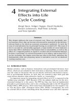
Ratio (CLR) is defined as shown in the equation shown in the Fig. 4-1. Lost
cells include cells that did not reach the destination, cells received with an
invalid header, cells corrupted by errors. In brief, lost cells include only
those which are sent but do not arrive within expected time.
The total transmitted cells figure in the equation is the total number of con-
forming cells, that is, cells that conform to the traffic descriptor. Cells that
are lost due to violation of their traffic descriptors are not counted when cal-
culating the CLR. Hence, only cells, which were admitted to the network,
are counted. The CLR, which in UNI 4.0 became a negotiable parameter,
has a value in the range 10
-15
to 10
-1
in increments of 10
-x
.
Chapter 4
63
For many services it is extremely important that the delay on end-to-end
basis is minimized and has a stable value. Although ATM is an asynchro-
nous transmission method, it can monitor and guarantee the delay for the
transmitted traffic. The second negotiable QoS parameter, Cell Transfer
Delay (CTD) is influenced by a number of factors. The factors include prop-
agation delay, switch design, buffer capacity and traffic load. An application
may require a service that can set an upper limit on the value of CTD. This
limit is referred to as Maximum Cell Transfer Delay (maxCTD), which can
be requested in the range of 10 ms to 16,777,215 ms with increments of 10
ms. Please note that CTD is a variable that changes its value randomly with
every cell received.
ATM Basics
64
Fig. 4-1, Cell Loss Ratio
The control of the maxCTD parameter does not ensure that every real-time
application can operate properly. Some services and applications require
that the delay the delay should not change its value during transmission of
sensitive data. For instance, the transmission of voice services over packet
switched networks is possible as long as the end-to-end delay fluctuates
within defined limits. The major source of variation of the CTD is related to
one of the fundamental ATM mechanisms - multiplexing of cells from dif-
ferent users. The processes of buffering and switching inevitably introduce
certain level of uncertainty in terms of delivery time for a single cell.
Chapter 4
65
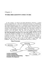
Fig. 4-2, Cell Delay Variation
Consequently, there was a need for the definition of another QoS parame-
ter: the Peak-to-Peak Cell Delay Variation (peak-to-peak CDV). It is the dif-
ference between the maximum CTD and the minimum CTD. Note that the
minimum CTD is made up of the fixed-delay components, that is, the
unavoidable delays such as a propagation, transmission and switching
delay. Peak-to-peak Cell Delay Variation, has been a negotiable parameter
since UNI 4.0 was introduced, is mainly affected by the ATM switch design,
buffer capacity, traffic load and the number of nodes in a system. CDV is
measured in the range 10 ms to 655350 ms, with an increment of 10 ms.
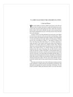
The relation between maxCTD and peak-to-peak CDV is explained in the
Fig. 4-3, where the cell arrival distribution as a function of arrival time is
presented. As can be easily noticed, for a given source, destination and
route, some minimum (fixed) delay always exists due to the physical char-
acteristics of the transmission path. However, only some cells make it in the
minimum time. Most of the cells, according to the probability density func-
tion are delivered within ranges set by the value of the maxCTD. But the
probability density function says that it is also possible that some cells can
reach the destination later than it is desired. Such cells will not be counted
as delivered properly and they are treated as lost cells. By choosing a value
of CTD, the customer and the carrier make an agreement on how late a cell
can be delivered and still count as a correctly delivered cell. Normally, CDV
is chosen so that, the fraction of cells that rejected for being too late be on
the order of 10
-10
or less.
ATM Basics
66
4.2.2 Non-negotiable QoS Parameters
The remaining three QoS parameters refer to the characteristics of the vir-
tual connection in terms of errors that can be caused at the time of trans-
mission and switching processes. The parameters’ definitions are given in
the Fig. 4-4.
Chapter 4
67
Fig. 4-3, The relation between CTD and CDV
CER (Cell Error Ratio) is defined as the number of ‘errored’ cells over the
number of successfully delivered cells plus the number of errored cells. An
errored cell is one that has been modified incorrectly, in such a way that it
cannot be efficiently recovered by error correction mechanisms. The CER
ratio is affected by the characteristics of the physical media being used.
Hence, CER has typically lower value if the physical medium is fiber as
opposed to a copper wire.
SECBR (Severely Errored Cell Block Ratio) is the fraction of N-cell blocks
of which M or more cells contain an error. Hence, it is defined as the num-
ber of severely errored cell blocks over the total transmitted cell blocks. A
cell block is the number of user cells transmitted between successive O&M
cells. The knowledge of this parameter can be helpful when there is a need
to investigate the nature of errors.
ATM Basics
68
Fig. 4-4, Non-negotiable QoS parameters
CMR (Cell Misinsertion Rate) is defined as the number of misinserted cells
over a particular time interval (the unit of the time interval is typically an
hour). A misinserted cell is one that is switched to a VC to which it does not
belong. This phenomenon is caused by undetected or miscorrected errors in
the cell header, which imply wrong switching decisions. The time interval is
usually taken to mean the lifetime of the virtual connection.
The non-negotiable parameters mentions are not signaled between user and
ATM network. Their meaning is descriptive, which means they can be mea-
sured, collected and analyzed, but they cannot be requested from the ATM
network as QoS objectives.
4.3 Traffic Descriptors
When a virtual circuit is established, both the user (typically the process in
the user device) and the network operator (the ATM network layer) must
agree that certain conditions must be applied to this circuit. This bi-direc-
tional agreement is called a traffic contract (similar to the SLA in IP net-
works) and may even have legal implications in the case of a public network.
The traffic contract consists of three elements: the specification of offered
traffic characteristics, the set of QoS parameters, and the conformance def-
inition.
The first part of the traffic contract is the traffic descriptor containing traf-
fic parameters. The user needs to specify his requirements in terms of traf-
fic characteristics. Depending on the QoS category different traffic parame-
ters can be included in the contract. The whole set of parameters that can
be set at the user side includes:
•PCR (Peak Cell Rate), which is the maximum rate at which the
sender is planning to send cells. The upper limit for this parameter is
constrained by the physical medium capabilities. The unit of this para-
meter is a cell per second [cps]. The opposite of the PCR, which is 1/PCR,
indicates how often cells are generated at the transmit side.
Chapter 4
69
•SCR (Sustainable Cell Rate) is the expected or required average
cell rate that is measured over a long time interval. In case of the CBR
traffic, SCR is equal to PCR, but for other QoS categories is always lower
than PCR.
•MCR (Minimum Cell Rate) is the minimum rate the user considers
acceptable during the whole time of the connection. Due to the conges-
tion control mechanism that is deployed in the ABR QoS category, the
actual bit rate varies dynamically between MCR and PCR.
•MBS (Maximum Burst Size) is the maximum number of cells that
can be transmitted at the PCR. MBS is expressed in the unit of cells.
This parameter has its equivalent parameter called BT (Burst
Tolerance), which is expressed in seconds and employed as the measure
for conformance checking of the SCR.
Each type of AAL uses its own set of traffic parameters. The relation
between QoS Categories and traffic parameters is given in the Fig. 4.5.
ATM Basics
70
Fig. 4-5, Relations between QoS categories and traffic parameters
There is also a traffic parameter that describes to the capabilities of network
devices. The CDVT (Cell Delay Variation Tolerance) informs how much vari-
ation will be present in cell transmission times. In other words, it describes
the ability of a switch to buffer incoming cells if their actual rate exceeds the
agreed PCR temporarily.
4.4 Traffic management
Quality of Service is one of the most important issues of ATM networks, in
part because of the variety of services supported. As it was mentioned ear-
lier, the user and the carrier must agree on a traffic contract. The exact user
requirements are coded with the help of traffic parameters and QoS para-
meters. According to the agreed contract, the network must be able to deliv-
er requested service with adequate QoS provided the user offers a traffic
which doesn’t break the rules set in the contract. On the other hand, carri-
ers desire to maximize the efficiency of their network resources and fill the
trunks to the highest capacity possible while still trying to fulfill the traffic
contract requirements.
The traffic load in ATM networks changes randomly. As ATM cells traverse
the network, they can enter the congested area. Some network elements my
slow down the transmission that can bring some amount of delay as a result
of congestion. What’s more due to occasional network failures some cell may
become lost. Cells representing traffic from different users and of different
classes are switched, multiplexed, and buffered. Therefore, there is a need
for traffic management mechanisms capable of delivering desired QoS for
the users that signed a traffic contract. Their work starts when the customer
communicates to the network his traffic requirements. In case of SVCs, it is
the task for the signaling protocol to inform the network about the request-
ed characteristics of a new connection. The application software at the cus-
tomer device that uses its ATM API to communicate with the ATM network
initiates this process. Then all the parameters, depending on the service
class, are automatically sent with a signaling protocol (e.g. UNI) to the near-
est ATM switch. In PVC environment traffic characteristics are configured
manually at the user and the network side. Finally the network decides
whether it is feasible to accept a new connection with requested QoS. Once
Chapter 4
71
ATM Basics
72
the connection is established, the network permanently checks if the traffic
contract is not broken by the user equipment and ensures that the connec-
tion does not interfere with other services. As can be easily noticed, traffic
management in ATM is not restricted to only one function. In fact several
different mechanisms are needed to provide QoS.
4.4.1 Connection Admission Control
In high-speed networks such as ATM it is not reasonable to wait for con-
gestion to occur and then take necessary measures, for instance telling the
source to slow down the transmission. This is due to the fact that in the
interval between sending the notification and having it arrived at the
source, thousands of additional packets may arrive and the situation may
deteriorate further. What is even more important, the nature of traffic (real-
time services) implies that for some sources it is not possible to slow down
their traffic. Consequently, ATM network work according to which it is bet-
ter to prevent congestion rather than recover from congestion. A tool for pre-
venting congestion in ATM network is called the Connection Admission
Control (CAC). This process uses traffic descriptors to determine the char-
acteristics of the new connection, the knowledge of the current network
capacity and committed load to other users. When a customer device wants
a new virtual circuit, it must describe the traffic to be offered and the ser-
vice expected (e.g. AAL type, QoS parameters, conformance definition). The
network (in fact the ATM switch) checks to see if it is possible to handle this
connection without adversely affecting existing connections and decreasing
the QoS they observe. Then multiple potential routes may have to be exam-
ined to find the one that would satisfy user requirements. If no route can be
located the call is rejected. However, the customer may lower his require-
ments with regards to service requested and try to establish the connection
again.
The implementation of the CAC mechanism is not subject to standardiza-
tion as it is internal to a switch and dependent on the carrier policies.
Chapter 4
73
4.4.2 Resource Reservation and Management
Resource reservation as well as resource management is the techniques of
reserving resources in advance, usually at setup time. Once the CAC process
has accepted a new call, network management support systems are used to
provision adequate resources in each network element along the route.
Information included in a traffic descriptor is used to reserve bandwidth in
network elements. This reservation must account for the user requirements
but at the same time it should maximize the utilization of network capacity
and avoid congestion. The common approach to simplify the network traffic
engineering problems by segregating the different types of traffic, which has
similar characteristics and QoS needs onto separate connections. For exam-
ple all the CBR connections can be grouped within one Virtual Path. This
approach works fine as long as reservations are made for a connection that
request only the peak rate. Such connections are typically of long term dura-
tion, so the reservation can be performed manually. The traffic descriptor
can contain not only the peak bandwidth, but also the average bandwidth
(e.g. SCR). The trouble is that VBR services generate traffic of bursty
nature, thus taking the advantage of statistical multiplexing. For such a
service category manual reservation of resources is not efficient and may
lead to overprovisioning of network resources. Hence, more automated
mechanisms such as CAC accompanied by signaling and dynamic routing
capabilities based on traffic management and link state information are
needed. The primary objective for the network is to reserve the resources in
a way that resources should be available for traffic of any QoS category at
any time.
4.4.3 Usage Parameter Control
Usage Parameter Control (UPC), sometimes referred to as traffic policing, is
the term used to describe the techniques that the node employs at the UNI
to ensure that the user conforms to the traffic contract. The primary task of
the UPC function is to make sure that the traffic generated at specific
sources does not deteriorate the QoS observed by the customers who offered
traffic according to their traffic contracts. The mechanism for using and
enforcing the quality of service parameters is based on a specific algorithm
called the Generic Cell Rate Algorithm (GCRA). The objective for the GCRA
is to check every cell to see if conforms to the parameters for its virtual con-
nection. The ATM Forum documents propose the two possible implementa-
tions of the GCRA: virtual scheduling algorithm and a leaky bucket algo-
rithm. The latter algorithm is presented in the Fig. 4-6. GCRA has two para-
meters: an incrementing factor, which is the maximum allowed arrival rate
(PCR in case of CBR) and a limiting factor, which is the amount of variation
herein that is tolerable (CDVT in case of CBR).
ATM Basics
74
Fig. 4-6, The leaky bucket algorithm.
In normal conditions, all the cells transmitted at PCR enter the leaky buck-
et algorithm. As long as the minimum cell arrival time (the reciprocal of
PCR, T = 1/PCR) is equal to the value set in a traffic contract, cells drains
out through the hole at the bottom of the bucket and they are considered as
conforming cells. Assuming that PCR is equal to 100 cps (see case no 1), this
means that every 10 ms a new cell should arrive to the switch. The problem
arises with a sender who tends to generate cells more frequently, thus vio-
lating the agreed contract. If the cells are inserted to the leaky bucket with
too short time interval, the liquid level gradually increases. This is caused
by the fact that cells can leak at the bottom not quicker than with the PCR
but they enter the bucket with PCR’ which is slightly bigger (seen case no 2)
than PCR. Once the level of ‘liquid’ in the bucket is equal to CDVT value,
cell start leaking out. The cell that leaks out can be marked (CLP = 1) or
must be immediately discarded (in case of CBR QoS category).
The GCRA is also used to make sure the mean rate does not exceed SCR for
any substantial period. In fact for VBR-RT service category there is a
request to deploy two instance of CGRA. One of them will test the traffic
with incrementing factor of 1/PCR and limiting and CDVT, and the second
will use accordingly 1/SCR and BT parameters. In addition to providing a
tool for conformance testing the GCRA can also shape the traffic and remove
some of the burstiness.
4.4.4 Traffic Shaping
Workstations typically produce bursts of cells, so that it is difficult to mul-
tiplex such cells efficiently at the ATM layer. In order to cope with this prob-
lem a traffic shaping function can be implemented to spread out such cells
over a slightly longer period of time. In most cases traffic shaping is per-
formed before the traffic policing operation (UPC) is executed. This may
decrease the number of cells tagged and discarded. The ATM cell traffic is
monitored to smooth the stream of cells and avoid clumping of cells that
might result in cell loss due to delay variation. The traffic shaping operation
can be performed either at the egress of the user device or at the ingress of
the switching device at then network side.
Chapter 4
75
In practice, by using traffic shaping, much more efficient use can be made of
the network capacity. The penalty for this is reduced performance for users
of bursty data, since their bursts of data are spread out over a longer time
that can be difficult to cope with for some applications. There is no stan-
dardized mechanism for traffic shaping. In practice shaping needs only to
take place once, and that is at the customer premises equipment (CPE).
4.4.5 Cell Loss Priority Control
As it was presented in Chapter 2, every ATM cell contains the CLP field in
the header. This field is used to implement a very rudimentary control
mechanism. If the CLP bit is set to1 (CLP = 1), the cell can be discarded
depending on the actual network conditions and carrier policy. The cell with
the CLP field not set (CLP = 0) represents higher priority. The CLP control
mechanism may discard low priority cells during time of congestion. In
result the degradation of network service to all users whose cells are of high-
er priority is minimized. The cells that have CLP field not set can be subject
of tagging procedure if they violate the traffic contract. In fact all the cells
that are considered by the GCRA as non-conforming can have their CLP
changed from 0 to 1 or can be immediately discarded. The earlier alterna-
tive is more attractive to a customer as his traffic is likely to be delivered to
the destination unless congestion conditions occur along the route.
4.4.6 Explicit Forward Congestion Indication
The Explicit Forward Congestion Notification (EFCI) is the traffic manage-
ment mechanism that makes the use of the EFCI bit in the PTI field of an
ATM cell header. It is based on the idea that a node which experiences a con-
gestion state may notify its adjacent node (with regards to the virtual circuit
route) about the congestion. The EFCI bit is set when, for example, a buffer
threshold has been exceeded. The basic assumption behind this concept is
based on the conclusion that a receiver can notify the transmitter that in
turn slows down the transmission. Provided that the EFCI is implemented
at a large scale, the congestion should decrease or disappear. This approach
ATM Basics
76
has a number of constraints such dependence on the round trip delay and
customer behavior. However, when combined with other traffic manage-
ment mechanisms it may come out as the sufficient solution.
4.4.7 Rate-based Congestion Control in ABR Service
Both CBR and VBR traffic sources are of real-time or semi-real time nature.
For these traffic types it is generally not possible for the sender to adjust to
the actual network condition and slow down the transmission. However,
there is a group of services like the transport of network layer packets which
have dynamic and unpredictable nature on one hand, and can consume as
much bandwidth as possible while being the ‘best effort’ service at the same
time. Needless to say, due to the requirements of higher layers (including
application layer) they request for a minimum amount of bandwidth to oper-
ate efficiently. For this reason, the standard bodies defined ABR QoS cate-
gory. ABR service has been primarily designed for delay-tolerant and cell
loss-intolerant data applications. This category, as opposed to others, intro-
duces a dynamic cell rate-based network feedback mechanism and supports
a minimum cell rate. The basic model is that after every k data cells, each
source transmits a special RM (Resource Management) cell. The RM cell is
distinguished with the combination of bits in the PTI field of a cell header.
RM cells travel along the same path as the data cells, but it is treated in a
special way along the route. When it reaches the destination, it is examined,
updated, and sent back to the source. The path for RM cells is presented in
the Fig 4-7.
Chapter 4
77
The congestion control is based on the idea that each sender has a current
rate ACR (Actual Cell Rate) that is greater than MCR but lower than PCR.
When congestion is absent, ACR is increased up to PCR. If congestion
occurs, ACR is decreased. Each RM cell sent contains the rate at which the
sender would like to transmit. This value is called ER (Explicit Rate). The
RM cells passes along the path and the switches that are congested can
reduce the value of ER. Reduction can be imposed either in the forward or
in the reverse direction. Since no switch may increase it, the sender gets the
knowledge of what the current maximum acceptable rate is. Then it can
adjust ACR to transmit cells at the rate that the slowest switch in the path
can handle.
This short description does not cover the ABR related information com-
pletely so some further reading is advised. Detailed information on rate-
based congestion control is found in ATM Forum Traffic Management 4.1.
ATM Basics
78
Figure 4-7, The path taken by RM cells in ABR operation