Machinery Components Maintenance And Repair Episode 2 Part 5 ppt
Bạn đang xem bản rút gọn của tài liệu. Xem và tải ngay bản đầy đủ của tài liệu tại đây (456.42 KB, 25 trang )
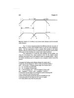
In Figure 7-44, the three curves show the difference in the axial deflec-
tions among Type R bearings with standard (AFBMA Class 0) and loose
(AFBMA Class 3) internal fits and the 7000 Series angular-contact bear-
ings (29° contact angle). Using the Type R standard fit curve as a basis of
comparison, the deflection for Type R loose fit bearings with 100 pounds
of thrust load is approximately 50 percent less while the 7000 Series is
about 85 percent less. As the thrust load is increased, the abrupt rise in
deflection shown for lower thrust loads is nearly eliminated. The leveling
out of curves continues and, at 2,400 pounds, the deflection rate is reduced
25 percent and 58 percent, respectively. This ratio between the curves
remains fairly constant for loads above this point.
This comparison shows that bearings which have a low degree of
contact angle (Type R standard fit) usually have the highest rate of axial
deflection. The greatest increase takes place under low thrust load. Bear-
ings with a high angle of contact, such as the 7000 Series, tend to retain
a more even rate of deflection throughout the entire range of thrust loads.
Figure 7-45 illustrates the difference in radial deflection among the
same types of bearings in Figure 7-44. The amount of radial deflection for
all three types is more closely grouped with small differences between
each type for the amount of radial load applied. In contrast to Figure 7-
44, radial deflection increases in relation to the degree of contact angle in
the bearing type. The Type R standard fit bearing which has an initial
contact angle of approximately 10° has a lower rate of radial deflection
than the 7000 Series bearing with an initial contact angle of 29°.
Figures 7-46, 7-47, and 7-48 illustrate the effects of light, medium, and
heavy preloads on bearings of each type. The top curve on each chart is
Ball Bearing Maintenance and Replacement 415
Figure 7-44. Axial deflections.
for duplexed unpreloaded bearings and is the same curve used on Chart
1, for a single bearing of the same type. The light, medium and heavy
preload curves show reduction of axial deflection that can be obtained for
bearings of each type. It is interesting to note that, in all cases, the axial
deflection for preloaded types is reduced throughout the entire curve. At
the low end of the applied loads, the increase is considerably less than in
unpreloaded bearing types and the deflection rate levels off throughout the
entire curve.
416 Machinery Component Maintenance and Repair
Figure 7-45. Radial deflections.
Figure 7-46. Axial deflections for type R standard fit bearings.
The deflection curves presented on these charts represent calculations
determined from 207-R and 7207 bearings. These specific axial and radial
deflection conditions occur only in these bearings. However, in general,
these curves do indicate what may occur in other bearings in the same
series. Both axial and radial deflection characteristics will change in
general proportion as the bearing size in the same series is increased.
It is the relationship between load and axial and radial deflections that
frequently makes it desirable to preload bearings. Preload refers to an
initial predetermined internal thrust load incorporated into bearings for
Ball Bearing Maintenance and Replacement 417
Figure 7-47. Axial deflections for type R loose fit bearings.
Figure 7-48. Axial deflections for 7000 series bearings.
the purpose of obtaining greater axial and radial rigidity. By careful selec-
tion of bearing type and amount of preload, axial and radial deflection
rates best suited to a specific application can be obtained.
When a duplex pair with preload is mounted back-to-back (Figure 7-
49) there is a gap between the two inner rings. As the two bearings are
clamped together, the two inner rings come in contact to eliminate the gap.
This changes the ball position to contact both inner and outer raceways
under load establishing the basic contact angle of the bearings. The cen-
terline on the balls shows this change. Bearings duplexed back-to-back
greatly increase the effective shaft rigidity especially to misalignment.
When equal (and square) pairs of spacers are used with these bearings,
effective rigidity is increased still further.
In the face-to-face arrangement (Figure 7-50), the preload offset is
between the outer rings. After clamping, the balls come into contact with
both inner and outer races at the basic contact angle. Effective radial rigid-
ity of the shaft is equal to that of the back-to-back arrangement; but less
rigidity is given to conditions of misalignment.
Preloading is accomplished by controlling very precisely the relation-
ship between the inner and outer ring faces. A special grinding procedure
creates an offset between the faces of the inner and outer rings of the
bearing equal to the axial deflection of the bearing under the specified
preload.
When two bearings processed in an identical manner are clamped
together, the offset is eliminated, forcing the inner and outer rings (depend-
ing on where the offset occurs) to apply a thrust load on the balls and race-
ways even before rotation is started. This results in deflection in the contact
areas between the balls and races that corresponds to the amount of
preload that has been built into the bearings. Balls are forced to contact
418 Machinery Component Maintenance and Repair
Figure 7-49. Duplex pair with preload mounted back-to-back.
the raceways immediately upon clamping the bearings together, thus elim-
inating the internal looseness. An additional load applied to the set of bear-
ings will result in deflections of considerably smaller value than would be
the case if the bearings were not preloaded.
Preload Offset
The relationship of the inner and outer ring faces of DB and DF pairs
of bearings duplexed for preload is shown in Figures 7-49 and 7-50. Note
the gap between the inner rings of the DB pair and the outer rings of the
DF pair. This is referred to as preload offset. In the illustrations the offset
has been greatly exaggerated to show the action that takes place. In most
cases the offset is so small that it cannot be detected without the proper
gauging equipment.
DTDB and DTDF Sets
Tandem duplex bearings may be preloaded under certain conditions.
These are applications where a tandem set of two or more bearings is
assembled either DB or DF with a single bearing (Figure 7-51) or another
tandem set of two or more bearings. Preload in these sets is the clamping
force, applied across outboard sides of the set, necessary to bring all
mating surfaces in contact.
Ball Bearing Maintenance and Replacement 419
Figure 7-50. Face-to-face arrangement.
Preload for individual tandem bearings in a set must be equal to the
preload of the set divided by the number of bearings on each side.
Example: Three DT bearings are matched DB with two DT bearings.
The set has a 600 lb preload.
Each of these DT bearings (one side) must have preload of 600/3 or
200 lbs.
Each of the two DT bearings (other side of set) must have 600/2 or
300 lbs.
Importance of the Correct Amount of Preload
Since the deflection rate of a bearing decreases with increasing load as
shown in Figures 7-44 and 7-45, it is possible, through preloading, to elim-
inate most of the potential deflection of a bearing under load. It is impor-
tant to provide the correct amount of preload in each set of duplex bearings
to impart the proper rigidity to the shaft. However, rigidity is not increased
proportionately to the amount of preload. Excessive preload not only
causes the bearings to run hotter at a higher speed but also reduces the
operating speed range. As machine tools must perform many types of work
under varying conditions, the proper preload must be provided for each
bearing to meet these conditions while retaining operating temperatures
and speed ranges to which the bearings are subjected.
Duplex bearings are generally manufactured so that the proper amount
of preload is obtained when the inner and outer rings are simply clamped
420 Machinery Component Maintenance and Repair
Figure 7-51. A tandem set of two or more bearings is assembled DB or DF with single
bearing.
together. If the duplex bearing has the correct preload, the machine will
function satisfactorily with the proper shaft rigidity and with no excessive
operating temperature. Any change in the initial preload is generally unde-
sirable and should be made only if absolutely necessary. This is especially
true for machine tool spindle bearings that are made to extremely fine tol-
erances. Any attempt to change the initial preload in these bearings is more
likely to aggravate the faulty condition than correct it.
Factors Affecting Preload
There are various conditions which may adversely affect the initial
preload in duplex bearings:
•
Inaccurate machining of parts can produce a different preload than
originally intended, either increasing or decreasing it depending upon
the nature of the inaccuracy
•
Use of spacers that are not equal in length or do not have the faces
square with the reference diameter (OD or ID) can produce an
improper preload
•
Foreign matter deposited on surfaces or lodged between abutting
parts as well as nicks caused by abuse in handling may produce
cocking of the bearing and misalignment. Either condition can result
in a variation of the preload or binding in the bearing.
The following precautions should be taken to avoid distortion when the
parts are clamped together.
•
Make a careful check of the shaft housing shoulder faces and the end
cover surfaces abutting the bearing to see that they are square with
the axis of rotation
•
Make sure that the end surfaces of each spacer are parallel with each
other and square with the spacer bore
•
Carefully inspect the lock nut faces for squareness
•
Inspect all contacting and locating surfaces to make sure they are
clean and free from surface damage
Preload Classifications
MRC brand Type R and 7000 Series angular-contact ball bearings are
available with any of three classes of preloads—light, medium, or heavy.
The magnitude of the preload depends upon the speed of the spindle and
required operating temperatures and rigidity requirements.
Ball Bearing Maintenance and Replacement 421
Preloaded Replacement Bearings
Normally replacement duplex bearings will be supplied universally
ground with predetermined light preload. These are designated as “DS”
bearings. If preload recommendations are desired when ordering bearings,
all data possible, such as the equipment in which the spindle is used,
spindle speeds, loads, and lubrication, should be supplied.
Preloaded Bearings with Different Contact Angles
Less than 5 percent of all pump bearings reach their calculated life.
Compared to the average calculated thrust bearing life of 15 to 20 years,
actual application life for pump bearings in the hydrocarbon processing
industry (HPI) is only 38 months or less based on 2004 data.
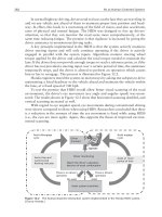
Preloaded bearings with different contact angles can significantly
increase the service life of bearings in many pump applications. The key
to their superior performance lies in the system’s directionally dissimilar
yet interactive spring rates. One such bearing system, MRC’s “PumPac,”
consists of a matched set of 40° and 15° angular contact ball bearings with
computer-optimized internal design. It is designed to interact as a system,
with each component performing a specific function.
By using this special set of bearings, ball skidding and shuttling are
virtually eliminated. The result: lower operating temperatures, stable oil
viscosity, consistent film thickness, and longer service life.
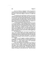
Figure 7-52 depicts a shaft equipped with MRC’s “PumPac.” The two
bearings are mounted back-to-back, with the apex of the etched “V” point-
ing in the direction of predominant thrust.
422 Machinery Component Maintenance and Repair
Figure 7-52. Preloaded thrust bearing set with different contact angles counteracts skidding
of rolling elements (courtesy MRC Bearings, Jamestown, New York).
Assembly of Bearings on Shaft
Bearing Salvage vs. Replacement Considerations
The final decision now must be made whether to reuse the bearings
removed from the spindle or to replace them with new bearings. The
choice probably will be self-evident, especially after the visual inspection
mentioned in item #5 on the checklist in Table 7-5.
If the bearing has defects that will affect its operation, it must be
replaced with a new bearing of the same size and tolerance grade.
Experience will be a guide in determining if the bearing is to be
replaced. The apparent condition of a bearing will not be always a decid-
ing factor. Bearings can still be used if they are not badly pitted or
brinelled on nonoperating surfaces. This also applies to bearings that do
not show excessive wear or signs of overheating. There are some instances
where the boundary dimensions may have been affected by operation.
Where possible, they should be checked to determine if they are within
the desired tolerances.
Often a simple check on a bearing’s internal contact surfaces can be
made by spinning the bearing by hand. This may be done after the bearing
has been thoroughly cleaned to eliminate possible harmful grit inside it.
If the bearing has some imperfect contact surface, this can be felt when
Ball Bearing Maintenance and Replacement 423
Table 7-5
Spindle Servicing Checklist
At this point, all cleaning and repair work on the shaft and spindle parts should have
been completed. A review of all steps taken in the servicing of a spindle are listed here
for checking purposes.
1. Remove shaft and bearings from the housing.
2. Dismount bearing from shaft using arbor press or bearing puller.
3. Tag bearings and spacers (if any) for identification and proper location when
remounting on the shaft.
4. Clean bearings and spindle parts.
5. Make visual inspection of all spindle parts for nicks, burrs, corrosion, other signs of
damage.
6. Prepare shaft for remounting of bearings. Make any repairs necessary on bearing
seat, shaft shoulders, fillets, etc.
7. Prepare housings by making any required repairs on machine mounting surfaces,
Paint non-functional surfaces as necessary.
8. Check shaft and housing measurements for bearing seat out-of-round, off-square
shoulders, housing bore, etc.
spinning the outer ring slowly while holding the inner ring (Figure 7-53).
This test should be made under both lubricated and dry conditions.
However, when dry, extreme care must be taken when spinning the bearing
as the rolling surfaces of the balls and raceways are even more sensitive
to possible scratching by grit.
Another point to consider is anticipated bearing life. If a bearing has
been in service for a long time and, according to the records, is nearing
the end of its natural life, it should be replaced with a new bearing. If a
longer life can be expected, then an evaluation must be made comparing
the cost of a replacement bearing against the remaining life of the old
bearing and its later replacement. Also, the evaluation should take into
account the possibility of new bearings in certain services having a
statistically provable higher failure rate than bearings that have been in
successful short time service.
If a replacement bearing is to be used, it should be understood that
dimensional interchangeability does not necessarily guarantee functional
interchangeability. In certain applications, there are other characteristics
424 Machinery Component Maintenance and Repair
Figure 7-53. Check internal contact surfaces by turning outer ring slowly while holding inner
ring.
such as internal fit, type and material of cage, lubricant, etc., that are of
vital importance. If you have questions about the selection of the correct
ball bearing replacement, it is always wise to consult the product engi-
neering department of capable major bearing manufactuers.
Cautions to Observe During Assembly of Bearings into Units
Whether using the original bearing or replacing it with a new one, care
must be taken to avoid contamination when mounting the bearing. A
critical period in the life of a bearing starts when it leaves the stockroom
for the assembly bench where it is removed from its box and protective
covering. This critical period continues until the bearing passes its first
full-load test after assembly. Here are a few rules that should be observed
during this crucial period.
1. Do not permit a bearing to lie around uncovered on work benches
(Figure 7-54).
2. Do not remove a bearing from its box and protective covering until
ready for installation.
3. When handling bearings, keep hands and tools clean.
4. Do not wash out factory-applied lubricant unless the bearing has
become exposed to contamination.
5. If additional lubrication must be applied, be sure it is absolutely
clean. In addition, the instrument used for application must be clean,
and chip and splinter proof.
Ball Bearing Maintenance and Replacement 425
Figure 7-54. Keep unboxed bearings covered until ready for mounting.
6. If subassemblies are left for any length of time, they should be lightly
covered with clean, lintless material (Figure 7-55).
Some other precautions to be exercised during assembly were discussed
under “Cleanliness and Working Conditions” earlier. If there is any chance
that the bearing may have become contaminated, don’t take any chances—
wash the bearing again following the procedure outlined in that section.
In summary, many precautions have been taken by the bearing manu-
facturer to make sure that the bearings are delivered in a clean condition.
In a few seconds, carelessness can destroy the protective measures of the
manufacturer shorten the life of the bearing jeopardize the reputa-
tion of the organization for which you work. It pays to do everything pos-
sible to prevent abrasive action caused by dirt in a bearing. But assembly
precautions do not stop here. The user must resist his inclination to “clean”
a bearing by removing the preservative coating applied by the bearing
manufacturer. Prelubrication is not usually necessary and extreme
vulnerability can he introduced by precoating certain rolling element
bearings with extreme light viscosity or inferior quality oils.
High Point of Eccentricity
When remounting bearings with tolerance grades of ABEC-5, ABEC-
7, or ABEC-9, it is essential to orient them on the shaft with reference to
the “high point of eccentricity.” Super-precision bearings are usually
marked to indicate this detail.
426 Machinery Component Maintenance and Repair
Figure 7-55. Cover subassemblies, especially those with mounted bearings, with plastic
material while waiting to assemble into housing.
The high point of eccentricity of the outer ring is the highest reading
obtained when measuring its radial runout. It is found by placing the
bearing on a stationary arbor and applying an indicator directly over the
ball path on the outside diameter of the outer ring. When the outer ring
is rotated, the difference between the highest and lowest reading is the
amount of radial runout of the outer ring. The high point of eccentricity
of the inner ring is determined in the same manner except that the inner
ring is rotated. To indicate the high point of eccentricity, a dot is burnished
on both inner and outer rings (Figure 7-56) on Type R and 7000 Series
angular-contact bearings of ABEC-5 or higher tolerance grades.
The burnished dots are applied to the rings so that the bearings can be
mounted to reduce or cancel the effects of shaft seat runouts. When
mounted, the dots should be 180° from the high point of eccentricity of
the bearing seat on each end of the shaft. The high point of eccentricity
of the shaft also should be determined and marked when the shaft is on
centers (or V-blocks). This method of mounting will help keep radial
runout of the spindle assembly to a minimum. This is important especially
in high speed applications. Matching the burnish marks in duplexed bear-
ings will reduce internal fight between bearings.
Thrust Here
The words “Thrust Here” are stamped on the back of the outer ring of
all MRC brand Type R and angular-contact bearings. This serves as a
guide when mounting the bearing so that the shaft thrust carries through
the bearing (Figure 7-57). Note that in the “right” method of mounting,
Ball Bearing Maintenance and Replacement 427
Figure 7-56. Burnished dots show high point of eccentricity.
the thrust is along the shaft, through the inner ring along the angle of
contact of the balls, through the heavy shoulder of the outer ring (stamped
“Thrust Here”) to the shoulder of the housing.
If the bearing position were reversed as shown in the “wrong” method,
the shaft thrust would follow the angle of contact through the low shoul-
der side of the outer ring. As the outer ring will not carry loads of any
magnitude, it is likely that the thrust would then force the balls to ride the
edge of the low shoulder. This could cause early failure due to concen-
trated loads at the race-shoulder intersection and possibly even cause
cracking of the balls.
Mount Bearings with Push Fit
Precision bearings used in the machine tool industry normally are
mounted on the shaft with a push fit, that is, pressing the bearing in place
(Figure 7-58) with hand pressure. In some cases, the original bearings may
be used again. No difficulty should be encountered while mounting them.
However, if a new bearing is to be used, the proper tolerance grade bearing
must be selected so that a push fit results. An application of light oil on
the shaft will increase ease of mounting.
428 Machinery Component Maintenance and Repair
Figure 7-57. “THRUST HERE” on outer ring shows the side of the ring to which shaft thrust
is to be imposed. Improper mounting may force balls to ride the edge of the low shoulder.
Mounting with Heat
If a bearing is to be mounted with a tighter than “push” fit, a conve-
nient and acceptable method of mounting is to expand the rings by
moderate heating. To make sure the bearing is not overheated, a thermo-
statically controlled heat source should be used. An inexpensive type of
household oven will usually serve the purpose satisfactorily. The oven also
protects the bearing from contamination while being heated.
Before heating, the bearing must be removed from its plastic packing
bag or other wrapping as the temperature reached may melt the material.
If gloves are used when handling the bearing, they should be made of a
lint-free material such as nylon or neoprene. Set the thermostat to a tem-
perature between 175°F and 200°F (80° to 94°C). In most cases, this will
be adequate to expand the bearing without overheating it. Heat the bearing
a sufficient amount of time to allow for ring expansion. Upon removal,
slip the bearing on the shaft immediately with full regard for direction of
thrust as well as orientation of the high points of eccentricity of both
bearing and shaft. Certain bearings not employing cages, seals, or lubri-
cants susceptible to damage at the higher temperature may be heated to
275°F (136°C).
Induction heaters (Figures 7-59 through 7-61) offer several different
heating programs to suit user requirements in a variety of situations. The
heaters are suitable for continuous use, and their compact temperature
probes ensure exceptionally exact temperature control. Most importantly,
Ball Bearing Maintenance and Replacement 429
Figure 7-58. Shaft is held in a vise when mounting bearing with a push fit. Cover vise jaws
with wood or soft metal.
430 Machinery Component Maintenance and Repair
Figure 7-59. Typical induction heater for mounting rolling element bearings (courtesy
Prüftechnik A. G., Ismaning, Germany).
Figure 7-60. Large induction heater used for bearing assembly on machinery shafts
(courtesy Prüftechnik A. G., Ismaning, Germany).
properly engineered, state-of-the-art induction heaters completely
demagnetize the bearing automatically at the end of the heating cycle,
because, otherwise, the magnetized bearing would literally act as a
trash collector for ferritic particles, leading to an untimely demise of the
bearing.
Large induction heaters include features such as swivel-arm crossbar
design and a pedal-operated crossbar lift, which allows one-man opera-
tion even when mounting extremely large workpieces, while the heavy,
welded-steel carriage provides on-site portability. Further features might
include auto demagnetization, automatic temperature probe recogni-
tion, dynamic heating power regulation, and suitability for continuous
operation.
Typical technical data of large units are as follows:
Power consumption: 14 kVA max.
Heating capacity: approx. 400kg (880lb)
Heating duration: 10 sec 1hr
Precision, Time: +1 sec.
Temperature: +2°C (3.6°F)
More compact and still robust, smaller units may offer such standard
features as microprocessor-controlled heating by time or temperature, auto
demagnetization, automatic temperature probe recognition, and dynamic
Ball Bearing Maintenance and Replacement 431
Figure 7-61. Compact bearing induction heater (courtesy Prüftechnik A. G., 8045
Ismaning, Germany).
heating power regulation. Technical data of the more compact units are
typically as follows:
Power consumption: 3.5 kVA max.
Heating capacity: approx. 15 kg (33 lb)
Heating duration: 10sec 1hr
Precision: better than 3°C (5.4°F)
Time: +1 sec.
Temperature: +2°C (3.6°F)
Other Mounting Methods
A variation of the dry heat method to expand the bearing involves the
use of infrared lamps inside a foil-lined enclosure. The lamps should be
focused on the inner ring. Care must be taken to keep the temperature
below 200°F (94°C), except as noted previously (Figure 7-62).
It also is possible to use dry ice to cool the shaft which will then
contract sufficiently to permit mounting of the bearing with the proper
finger pressure. In this method, special precautions should be used to
prevent resulting condensation from producing corrosion on the bearing
components.
An arbor press and a hollow tube (Figure 7-63) are frequently employed
to mount bearings on shafts in those cases where press fits are involved.
432 Machinery Component Maintenance and Repair
Figure 7-62. A variation of the infrared lamp method suited for large size bearings. Take
care not to overheat the bearing.
When doing so, the press and the tube should be completely clean to avoid
possible contamination of the bearing. The tube must contact the inner
ring when pressing the bearing on the shaft (Figure 7-64). This will avoid
possible brinelling of the bearing which might occur if pressure were
applied on the outer ring. The press ram, tube, and bearing axis should be
in good alignment. If abnormal pressures are required, the alignment prob-
ably is not good enough. In this case, alternate application of pressure and
relief may help ease the pressure required.
Exercise Caution When Starting Bearing On Shaft
To start the bearing, the shaft should have a lead and the bearing
face should be square with the shaft (Figure 7-64). Pressure should be
in line with the shaft and must be uniform against the face when pres-
sing the bearing into place. If excessive binding occurs, it generally
indicates an off-square condition, a burr, high spots, a tapered shaft, dirt
or chips wedged under the bearing. When sticking or binding occurs,
the bearing should not be forced on the shaft as the hard inner ring is
apt to cut the softer metal of the shaft and raise a ridge or burr (Figure 7-
65). Remove the bearing from the shaft to determine and correct the
problem.
Ball Bearing Maintenance and Replacement 433
Figure 7-63. Arbor press and hollow tube method used to mount bearings on shafts when
press fits are involved.
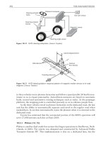
Checking Bearings and Shaft After Installation
After the bearings have been assembled on the shaft, a number of points
should be checked to make certain the bearings have been correctly
installed. These include visual checks and the use of various gauges to
determine the accuracy of the mounting. It also may be necessary to
balance the shaft assembly before insertion into the housing.
Check for Internal Clearance
The outer rings should rotate freely without binding except in unusual
cases where a tight fit has been specified or where preloaded duplexed
434 Machinery Component Maintenance and Repair
Figure 7-64. Bearing may be pressed on shaft using a tube and arbor press.
bearing sets are used. Residual internal clearance can be felt by holding
the outer ring between the thumb and forefinger (Figure 7-66) and rock-
ing it back and forth. If the bearing is free, the ring will have a slight
axial freedom of movement or “rock.” This applies to all single-row bear-
ings except a single bearing of the angular-contact type which is very
loose.
Ball Bearing Maintenance and Replacement 435
Figure 7-65. Result of starting bearing off-square.
Figure 7-66. Check a mounted bearing for internal clearance by rocking outer ring back
and forth.
Make Visual Check of Bearing
Be sure that the bearing is flush against the shaft shoulder all the way
around. The best simple check for this is to hold the shaft in front of a
light source such as a window or an electric light. If no light shows
between the inner ring face and the shaft shoulder, the bearing may be
considered in proper position. This check should be made all the way
around the shaft. If light is visible at any point, carefully remove the
bearing and recheck the shoulder and fillet for burrs, out-of-round or too
large a radius on the fillet.
Check the height of the shoulder against the height of the inner ring. In
general, it should be a minimum of about half the width of the inner ring
face. If heavy thrust pressures are involved, the shoulder should be higher.
Check for Bearing Squareness on the Shaft
Check the face of the outer ring for squareness of the inner ring with
the shaft using a suitable indicator (Figure 7-67). The assembled front and
rear bearings or sets of bearings should be placed in V-blocks with an indi-
cator point contacting the face of the outer ring. When the shaft and inner
rings are turning, any off-square condition is transmitted through the balls
to the outer ring. This will cause the outer ring to rock or tilt and shows
up as a variation on the indicator reading. Readings in excess of the
bearing tolerances indicate an effective misalignment, resulting from an
off-square condition.
436 Machinery Component Maintenance and Repair
Figure 7-67. Checking for squareness of bearing on shaft.
Foreign matter between the bearings and shaft shoulder, fillet interfer-
ence, a nick on the shaft shoulder, raised metal from the bearing seat, a
nick on the spacer rings, and many other causes will produce this off-
square condition. Under these circumstances, remove the bearing from the
shaft to determine the actual cause and make the necessary repairs.
Balancing the Shaft Assembly
After the bearings and other units such as pulleys, etc., are properly
seated on the shaft, the assembly should be balanced, preferably dynami-
cally, to obtain a smooth-running spindle (Figure 7-68). All parts that
rotate with the assembled spindle should be included in the balancing
operation with whatever is applied to retain the bearings on the shaft.
Common Causes of Unbalance in Shaft Assemblies
Unbalance is commonly introduced through an eccentricity in some
portion of the shaft assembly that has not been properly finished. Eccen-
tricities may be present in the components affixed to the shaft. Ground
bearing seats may not be concentric with turned portions of the assembly.
Strains may develop in a shaft that has been heat-treated, causing warp in
the shaft that may create misalignment of the bearings. In other cases, a
thread may not be true to the shaft center. If the bore of the bearing spacer
is too loose when used, it may not be properly centered with respect to
the shaft axis. Causes of unbalance could include other factors in addition
to these items.
Correction of Unbalanced Shaft Assemblies
There are several methods to correct unbalance in either hardened or
soft shafts. In general, balancing consists of removing material from the
heavy side of the shaft or adding material to the light side of the shaft.
Any balancing operations should be conducted in an area removed from
the clean assembly area.
To balance a hardened shaft, sufficient material usually is removed to
create proper balance by grinding on the heavy side of the shaft nearest
the end which needs to be balanced. The grinding is usually done on a
portion of the shaft where the largest diameter occurs.
Several methods may be used to bring a soft shaft into balance. It is
possible to apply a correct amount of weight. It may be preferable to drill
Ball Bearing Maintenance and Replacement 437
a hole of the correct size and depth in the shaft. Metal generally is removed
from the shaft in the area of the largest diameter and at the greatest pos-
sible distance from the center of the shaft toward the end which must be
balanced. Extreme care must be taken to prevent the removed metal from
being introduced into the bearings mounted on the shaft.
Protect Bearings and Shaft Assembly from Contamination
After a ball bearing has been mounted on a shaft, often there is a time
interval, possibly overnight, before final installation in the housing can be
438 Machinery Component Maintenance and Repair
Figure 7-68. Dynamics of balancing spindle assembly. This equipment is used by TRW’s
Spindle Maintenance Department, but other types are available which will balance assem-
blies as accurately as necessary.
started. In such cases, it is advisable to wrap the bearings and shaft in
plastic film to protect them from contamination (Figure 7-69). If the bear-
ings are left exposed on the shaft, or even when installed in the housing,
dust and/or other contaminants may enter the bearing. If installed in the
housing, always be sure to cover the open end with film until all assem-
bly work is completed and the housing is completely closed.
Assembly of Shaft and Bearings into Housing
After the bearings have been assembled on the shaft, checked and bal-
anced, the entire assembly is ready for insertion into the housing (Figure
7-70) in accordance with the methods outlined in the manufacturer’s
manual. During this operation, care must be taken to start the bearings
into the housing seats squarely to avoid damage to the bearings or housing.
Any force exerted on the shaft passes through the bearings and, if exces-
sive, can cause bearing damage.
The outer ring generally should have a slightly loose fit in the housing.
This is necessary to permit the bearing axial movement to assume its
normal operating position regardless of temperatures which occur during
operation. If the bearing is too tight, axial movement is prevented and
violent overloads could result in nonfixed radial positioning of the shaft.
Ball Bearing Maintenance and Replacement 439
Figure 7-69. Protect bearings and shaft from contamination until assembled and completely
sealed in housing. Use plastic film to cover spindle.