Machinery Components Maintenance And Repair Episode 2 Part 3 ppt
Bạn đang xem bản rút gọn của tài liệu. Xem và tải ngay bản đầy đủ của tài liệu tại đây (541.57 KB, 25 trang )
For Jet Engine Balancing:
May be ordered from: Society of Automotive Engineers, Inc. (SAE) 400
Commonwealth Drive
Warrendale, PA 15096
Tel. (412) 776-4841
SAE ARP 587A Balancing Equipment for Jet Engine Compo-
nents, Compressors and Turbines, Rotating Type,
for Measuring Unbalance in One or More Than
One Transverse Planes. Contains machine and
proving rotor parameters and the all important
SAE acceptance test for horizontal machines.
SAE ARP 588A Static Balancing Equipment for Jet Engine Com-
ponents, Compressor and Turbine, Rotating Type,
for Measuring Unbalance in One Transverse
Plane. Contains machine and proving rotor para-
meters and acceptance test for vertical machines.
SAE ARP 1340 Periodic Surveillance Procedures for Horizontal
Dynamic Balancing Machines. An abbreviated
test that may be run periodically to assure proper
machine function.
SAE ARP 1342 Periodic Surveillance Procedures for Vertical,
Static Balancing Machines. An abbreviated test
that may be run periodically to assure proper
machine function.
SAE ARP 1382 Design Criteria for Balancing Machine Tooling.
Describes rotor supports, cradles, arbors, shrouds
and other typical accessories for horizontal and
vertical balancing machines. Also useful for
general balancing work.
SAE ARP 1202 Bell Type Slave Bearings for Rotor Support in
Dynamic Balancing Machines. Specifies dimen-
sions and tolerances for special balancing
bearings.
SAE ARP 1134 Adapter Interface—Turbine Engine Blade
Moment Weighing Scale. Standardizes adapter
tooling interface for blade moment weighing
scales.
SAE ARP 1136 Balance Classification of Turbine Rotor Blades.
Standardizes blade data and markings for classi-
fying moment weight.
Balancing of Machinery Components 365
Appendix 6-D
Critical Speeds of Solid and
Hollow Shafts
366
Part III
Maintenance and
Repair of Machinery
Components
This page intentionally left blank
Chapter 7
Ball Bearing Maintenance
and Replacement
The fundamental purpose of a bearing is to reduce friction and wear
between rotating parts that are in contact with one another in any mech-
anism. The length of time a machine will retain its original operating effi-
ciency and accuracy will depend upon the proper selection of bearings,
the care used while installing them, proper lubrication, and proper main-
tenance provided during actual operation.
The manufacturer of the machine is responsible for selecting the correct
type and size of bearings and properly applying the bearings in the equip-
ment. However, maintenance of the machine is the responsibility of the
user. A well-planned and systematic maintenance procedure will assure
extended operation of the machine. Failure to take the necessary precau-
tions will generally lead to machine downtime. It must also be remem-
bered that factors outside of the machine shaft may cause problems.
Engineering and Interchangeability Data
Rings and Balls—The standard material used in ball bearing rings and
balls is a vacuum processed high chromium steel identified as SAE 52100
or AISI-52100. Material quality for balls and bearing rings is maintained
by multiple inspections at the steel mill and upon receipt at the bearing
manufacturing plants. The 52100 bearing steel with standard heat treat-
ment can be operated satisfactorily at temperatures as high as 250°F
369
* Source: MRC Bearings, formerly TRW Bearing Division, now SKF Industries, Forms
455 and 382-13. Material copyrighted by TRW, Inc., 1982; all rights reserved. Reprinted
by permission.
(121°C). For higher operating temperatures, a special heat treatment is
required in order to give dimensional stability to the bearing parts.
Seals—Standard materials used in bearing seals are generally nitrile
rubber. The material is bonded to a pressed steel core or shield. Nitrile
rubber is unaffected by any type of lubricant commonly used in anti-
friction bearings. These closures have a useful temperature range of -70°
to +225°F (-56° to 107°C). For higher operating temperatures, special
seals of high temperature materials can be supplied.
Ball Cages—Ball cages are pressed from low carbon steel of SAE 1010
steel. This same material is used for bearing shields. Molded nylon cages
are now available for many bearing sizes. The machined cages ordinarily
supplied in super-precision ball bearings are made from laminated cotton
fabric impregnated with a phenolic resin. This type of cage material has
an upper temperature limit of 225°F (107°C) with grease and 250°F
(121°C) with oil for extended service. For periods of short exposure,
higher temperatures can be tolerated.
Lubricant—Prelubricated bearings are packed with an initial quantity of
high quality grease which is capable of lubricating the bearing for years
under certain operating conditions. As a general rule, standard greases will
yield satisfactory performance at temperatures up to 175°F (79°C), as long
as proper lubrication intervals and lube quantities are observed. Special
greases are available for service at much higher temperatures. Estimation
of grease life at elevated temperatures involves a complex relationship of
grease type, bearing size, speed, and load. Volume 4 of this series can
provide some guidance, although special problems are best referred to the
product engineering department of major bearing manufacturers.
Standardization
Bearing envelope dimensions and tolerances shown in this chapter are
based on data obtained from MRC/TRW Bearing Division. They comply
with standards established in the United States by the Annular Bearing
Engineers’ Committee (ABEC) of the Anti-Friction Bearing Manufac-
turers Association (AFBMA). These standards have also been approved
by the American Standards Association (ASA) and the International
Standards Organization (ISO). This assures the bearing user of all the
advantages of dimensional standardization. However, dimensional inter-
changeability is not necessarily an indication of functional interchange-
ability. Cage type, lubricant grade, internal fitting practice, and many other
details are necessary to establish complete functional interchangeability.
370 Machinery Component Maintenance and Repair
Ball Bearing Variations
Special purpose bearings are generally one of the types shown in Table
7-1 but with special features as noted. For ease of reference we are includ-
ing Table 7-2, “Commonly Used MRC Bearing Symbols,” and Table 7-3,
“Ball Bearing Interchange Table.”
Ball Bearing Maintenance and Replacement 371
Table 7-1
Special Purpose Bearings
(Text continued on page 376)
372 Machinery Component Maintenance and Repair
Table 7-2
Commonly Used MRC Bearing Symbols
Ball Bearing Maintenance and Replacement 373
Table 7-3
Ball Bearing Interchange Table
374 Machinery Component Maintenance and Repair
Table 7-3
Ball Bearing Interchange Table—cont’d
Ball Bearing Maintenance and Replacement 375
Table 7-3
Ball Bearing Interchange Table—cont’d
“Special” bearings include:
Adapter Type—Conrad type with a tapered adapter sleeve.
Aircraft Bearings—A category by themselves. Not related to other types
listed here.
Cartridge Type—Conrad type with both rings same width as a double-
row bearing.
Conveyor Roll—Conrad type. Special construction, wider than standard
built-in seals.
Felt Seal—Conrad type, unequal width rings.
Cleanliness and Working Conditions in Assembly Area
Many ball bearing difficulties are due to contaminants that have found
their way into the bearing after the machine has been placed in operation.
Contaminants generally include miscellaneous particles which, when
trapped inside the bearing, will permanently indent the balls and race-
ways under the tremendous pressures generated by the operating load
(Figure 7-1).
Average contact area stresses of 250,000lbs per square in. are not
uncommon in bearings. Due to the relatively small area of contact between
376 Machinery Component Maintenance and Repair
(Text continued from page 371)
Figure 7-1. Hard, coarse foreign matter causes small, round-edged depressions of various
sizes.
the ball and raceway, contact area pressures are very high even for lightly
loaded bearings. When rolling elements roll over contaminants, the
contact areas are greatly reduced and the pressure becomes extremely
high.
When abrasive material contaminates the lubricant, it is frequently
crushed to finer particles that cause wear to the ball and race surfaces. The
wear alters the geometry of the balls and races, increases the internal
looseness of the bearing, and roughens the load-carrying surfaces (Figure
7-2). Therefore, it is highly important to maintain a clean environment
when working on all bearing applications during servicing operations.
The assembly area should be isolated from all possible sources of con-
tamination. Filtered air will help eliminate contamination and a pressur-
ized and humidity-controlled area is advantageous to avoid moist and/or
corrosive atmospheres. Work benches, tools, clothing, and hands should
be free from dirt, lint, dust, and other contaminants detrimental to
bearings.
Surfaces of the work bench should be of splinter-free wood, phenolic
composition, or rubber-covered to avoid possible nicking of spindle parts
that could result from too hard a bench top. To maintain cleanliness, it is
suggested that the work area be covered with clean poly-coated kraft
paper, plastic, or other suitable material (Figure 7-3) which, when soiled,
can be easily and economically replaced.
Ball Bearing Maintenance and Replacement 377
Figure 7-2. Fine foreign matter laps the ball surfaces and ball races, causing wear.
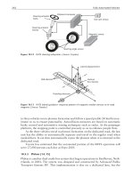
Removal of Shaft and Bearings from Housing
The first step in dismantling a spindle or shaft is to remove the shaft
assembly from the housing. To do this, it is generally necessary to take
off the housing covers from each end.
Most machine tool spindle and API pump housings are constructed with
bearing seats as an integral part of the housing. This contributes to the
rigidity of the spindle. However, it makes disassembly more difficult and
extreme care must be taken to avoid bearing damage. Also, it is not
generally possible to remove bearings from the shaft unless the shaft
assembly is first removed from the housing.
On most spindle assemblies this can be done by first placing the entire
spindle in an arbor press and in alignment with the press ram. Next, care-
fully apply pressure to the end of the shaft making sure that there is clear-
ance for the expulsion of the shaft assembly on the press table. As pressure
is applied, the shaft is forced from the housing along with the bearing
mounted on the opposite end of the shaft.
The bearing on the end where pressure is applied remains in the
housing. It is removed from the housing either with hand pressure or by
carefully pushing it out of the housing from the opposite side with rod
tubing having a diameter slightly smaller than the housing bore. The
tubing should contact the bearing outer ring and should push it from the
housing with little or no pressure on the balls and inner ring. Following
378 Machinery Component Maintenance and Repair
Figure 7-3. Cover workbench with clean, lint-free paper, plastic, or similar material. Also,
isolate work area from contamination sources.
this procedure will help avoid brinelling of the raceways due to excessive
pressure on the rolling elements and races.
Electric motor shafts are generally constructed to permit removal of one
end bell, leaving the shaft and bearings exposed. The rotor or shaft assem-
bly is then free to be removed by drawing it through the stator.
Bearing Removal from Shaft
Removal of bearings from spindle shafts is a highly important part of
the maintenance and service operation. In most cases, it is far more diffi-
cult to remove a bearing from the shaft than to put it on. For this reason,
a bearing can be damaged unnecessarily in the process. Every precaution
must be taken to avoid damage to any of the parts including the bearings.
If the bearings are damaged during removal, the damage often is not
noticed and may not become known until the spindle is completely
reassembled.
Bearing damage during removal from the shaft can occur in many ways,
of which these are the most common:
•
The smooth, highly-polished surface of the ball raceways may be
brinelled, i.e., indented, by the balls (Figure 7-4). Brinell marks on
Ball Bearing Maintenance and Replacement 379
Figure 7-4. Brinell marks or nicks, indicated by arrows, are the most common result of
improper bearing removal.
the surface of the races are usually caused when a bearing is forced
off the shaft by applying excessive or uneven pressure through the
rolling element complement. Any shock load, such as hammer blows
on the inner or outer rings, is apt to cause brinelling. Major brinelling
can sometimes be discovered on the job by applying a thrust load
from each direction while rotating the inner or outer ring slowly. As
the ring is turned through the brinelled area on either of the race
shoulders, it can often be felt as a catch or rough spot. A brinelled
bearing is unfit for further use. Never put it back into service.
•
Ball raceways may be roughened due to dirt particles or metal chips
working into the bearing. As soon as the shaft has been removed from
the housing, it should be placed in a clean work area and suitably
covered so that no contaminant can become lodged in the bearing
prior to removal from the shaft. If contaminants enter the housing
and the bearing is subsequently rotated, it is possible that they will
roughen and damage the raceways.
•
The ball cage may be damaged if the bearing puller is used incor-
rectly. Use of improper tools such as a hammer or chisel to pound or
pry the bearing off the shaft may result in damage to the bearing in
addition to the hazard of contaminating the bearing.
Removal From Shaft
Because of operating conditions or location of the shaft, bearings are
often tight and resist easy removal. This holds true even though they were
originally mounted with a “push” fit, usual in most machine tool spindle
applications. A “push” fit means ability to press the bearing on the shaft
with hand pressure.
If these conditions occur, mechanical means such as a bearing puller
(Figure 7-5) or the use of an arbor press (Figure 7-6) should be employed
to effect bearing removal. The hammer and drift tube method, sometimes
used to pound the bearing from the shaft, generally is not recommended,
especially on machine tool spindle bearings. There is always the chance
that the hammer shocks conducted through the tube will cause brinelling.
For some types of bearings, electrical means of removal are possible as
well. These removal methods will be described later.
Bearings are mounted on shafts or spindles in several ways so that dis-
mounting must be accomplished by different means. Here are the most
common conditions:
•
The bearing is free of grease and/or other parts. Place the shaft in an
arbor press in line with the ram and with the inner ring of the bearing
380 Machinery Component Maintenance and Repair
Ball Bearing Maintenance and Replacement 381
Figure 7-5. Bearing puller with two claws.
Figure 7-6. Using arbor press and split ring to remove bearing from shaft.
supported by a split ring having a bore slightly larger than the shaft
(Figure 7-7). Press the shaft from the bearing with an even pressure,
making sure it does not drop free and become damaged. If the split
ring is not available, two flat bars of equal height could support the
bearing (Figure 7-8).
Another means of removing a bearing from the shaft is by use of a
bearing puller, several of which are shown in Figures 7-13 to 7-15.
•
The bearing mounted with gears and/or other parts abutting it (Figure
7-9). In most cases, a bearing in this location can only be removed
by a bearing puller which applies pressure on the outer ring (Figure
7-10). Extreme care must be exercised when applying pressure to
382 Machinery Component Maintenance and Repair
Figure 7-7. Split ring supports inner ring of bearing.
Figure 7-8. Equal height bars spaced to support both inner and outer rings.
make sure that the pull is steady and equal all around the outer ring.
If the gears or other parts are removable, it may be possible to apply
pressure through them to force the bearing off the shaft. An arbor
press may be employed to do the job if the bearing or gear can be
adequately supported while pressure is applied.
Applying Pressure with Bearing Puller
Whenever possible, bearings always should be moved from the shaft by
square and steady pressure against the tight ring. Thus with a tight fit on
the shaft, pressure should be against the inner ring; with a tight fit in the
housing, pressure should be against the outer ring. If it is impractical to
Ball Bearing Maintenance and Replacement 383
Figure 7-9. Bearing mounted with other parts abutting it.
Figure 7-10. Where shaft parts obstruct inner ring accessibility, apply pressure with bearing
puller on outer ring as evenly and squarely as possible. On bearings with one high and one
low shoulder, pressure should be applied against the deep shoulder only.
exert pressure against the tight ring, and the loose ring must be used, it is
imperative that the same square and steady pull method be used.
Pressure may be applied in either direction on bearings with shoulders
of equal height (Figure 7-11). On counterbored bearings with one deep
and one low shoulder, pressure should be applied against the deep shoul-
der. If pressure is applied against the low shoulder, disassembly of the
bearing or serious damage may result. When the pairs of bearings on each
end of the shaft are mounted in a back-to-back (DB) relationship, the
counterbored outer ring is always exposed. In such cases, it will be nec-
essary to apply the pressure against the low shoulder (counterbored ring)
to effect bearing removal from the shaft even though the risk of damage
to the inboard bearing is great.
Most machine tool spindles employ Type R or angular-contact bearings
(7000 Series) that do not have seals or shields. However, it is possible that
a Conrad type bearing equipped with seals or shields may be used in some
applications. When using pullers for bearing removal, care must be exer-
cised to avoid damage to the seal or shield (Figure 7-12). If dented and
then remounted, an early bearing failure during operation could result.
Bearing removal damage can be caused by the selection of the wrong
puller type as easily as it can with improper use of the correct puller. No
matter which puller is used, remember: if the bearing is not pulled off
squarely under steady pressure, it must be scrapped!
Identification and Handling of Removed Bearings
As it is possible that bearings may be suitable for remounting after ser-
vicing, it is necessary to replace them in exactly the same position on the
shaft. Therefore, each bearing must be specifically tagged to indicate its
384 Machinery Component Maintenance and Repair
Figure 7-11. Pressure may be applied in either direction with shoulders of equal height.
proper location. Duplex bearings should be tied together in their proper
relationship, DB, DF, or DT and the tag should also indicate the relation-
ship. If a spacer is used between duplex bearings, the tag should indicate
its position and relationship to the bearings.
On jobs where the bearing is being removed because performance has
not been fully successful, it is often desirable to find out why. Be sure to
preserve the bearing until it is practical to examine it. The bearing fre-
quently contains direct evidence as to the cause of failure. It should not
be permitted to rust badly and the parts should be abused as little as pos-
sible during disassembly.
If the bearing is being removed for reasons other than bearing failure,
be certain that it is thoroughly cleaned and oiled immediately after
removal. Otherwise there is a good chance that it will get dirty and rusty,
which would prevent its reuse.
Bearing Pullers
There are numerous types of bearing pullers on the market, any of
which would be satisfactory to use depending upon the dismounting sit-
uation encountered. A conventional claw type is used where there is suf-
ficient space behind the bearing puller claws to apply pressure to the
bearing. In the illustration (Figure 7-13), the claws are pressing against
the bearing preloading spring pack which in turn will force the duplex pair
of bearings and spacers from the spindle.
Another type of puller (Figure 7-14) uses a split-collar puller plate
(Figure 7-15), the flange of which presses against the inner ring of the
bearing. The puller bolts must be carefully adjusted so that the pulling
Ball Bearing Maintenance and Replacement 385
Figure 7-12. Where a shield or seal does not permit inner ring pressure, use bearing puller
with extreme care to avoid denting shield or seal.
pressure is equal all around the ring. The collar must be made in two pieces
so that it can be slipped behind the bearing. The collar hole should be
large enough so that the two pieces may be bolted together without grip-
ping the shaft.
Most bearing companies do not manufacture bearing pullers, but
many bearing distributors stock a variety of the various pullers described
above.
386 Machinery Component Maintenance and Repair
Figure 7-13. Claws pressing against the bearing spring pack will force the duplex pair of
bearings and spacers from the spindle.
Figure 7-14. Another type of puller. Pulling pressure is applied to inner ring.
Bearing Removal Through Application of Heat
The application of heat via special devices provides a rather straight-
forward way of removing inner bearing rings without damaging shafts.
The device shown in Figure 7-16 is initially heated by an induction heater
(see Figures 7-59 through 7-61, later in this chapter).
To remove the inner ring from a bearing assembly [Figure 7-17(1)], the
outer race and rolling elements must first be removed [Figure 7-17(2)].
The device is then heated to approximately 450°C (813°F) and slipped
over the exposed ring [Figure 7-17(3)]. By simultaneously twisting and
pulling [Figure 7-17(4)], the operator clamps the heated pull-off device
onto the ring. Within approximately 10 seconds, the ring will have
expanded to the point of looseness [Figure 7-17(5)] and can be removed.
Cleaning and Inspection of Spindle Parts
Insufficient attention is paid to small dust particles which constantly
blow around in the open air, But should a particle get in one’s eye, it
becomes highly irritating. In like manner, when dirt or grit works into a
ball bearing, it can become detrimental and often is the cause of bearing
failure.
It is so easy for foreign matter to get into the bearing that more than
ordinary care must be exercised to keep the bearing clean. Dirt can be
introduced into a bearing simply by exposing it to air in an unwrapped
Ball Bearing Maintenance and Replacement 387
Figure 7-15. Split collar puller plate.
state. Within a short period of time, the bearing can collect enough cont-
aminants to seriously affect its operation. Special care must be taken when
the bearing is mounted on a shaft, a time when it is most susceptible to
contamination. This cleanliness requirement also extends to the handl-
ing of spindle parts, as everything must be clean when replaced in the
assembly.
Cleaning the Bearing
During the process of removal from a shaft, the bearing is likely to have
become contaminated. The following procedure should be used to clean
the bearing for inspection purposes as well as to prepare it for possible
remounting on the shaft:
1. Dip the bearing in a clean solvent and rotate it slowly under very
light pressure as the solvent runs through the bearing (Figure 7-18).
Continue washing until all traces of grease and dirt have been
removed. Do not force the bearing during rotation.
388 Machinery Component Maintenance and Repair
Figure 7-16. Electrically heated “demotherm” device for removal of bearing inner rings from
shafts (courtesy Prüftechnik A. G., Ismaning, Germany).
2. Blow the bearing dry with clean, dry air while holding both inner
and outer rings to keep the air pressure from spinning them. This
avoids possible scratching of balls and raceways if grit still remains
in the bearing. A slow controlled hand rotation under light pressure
is advisable.
3. After blowing dry, rotate the bearing again slowly and gently to see
if dirt can still be detected. Rewash the bearing as many times as
necessary to remove all the dirt.
4. When clean, coat the bearing with oil immediately. Special attention
should be given to covering the raceways and balls to ensure pre-
vention of corrosion to the highly finished surfaces. Rotate the
bearing gently to coat all rolling surfaces with oil.
After cleaning, the bearing should be wrapped with lint-free material
such as plastic film to protect it from exposure to all contaminants. Unless
this is done, it may be necessary to repeat the cleaning procedure imme-
diately prior to remounting. As other spindle parts are cleaned, they also
should be covered to exclude contamination which could ultimately work
into the bearing.
Ball Bearing Maintenance and Replacement 389
Figure 7-17. An induction-heated pull-off device will effectively remove bearing inner rings
from shafts (courtesy Prüftechnik A.G., Germany).