Machinery Components Maintenance And Repair Episode 1 Part 6 potx
Bạn đang xem bản rút gọn của tài liệu. Xem và tải ngay bản đầy đủ của tài liệu tại đây (656.01 KB, 25 trang )
developing air pockets. The baseplate must also be well supported to
prevent severe distortion of the mounting surfaces due to the weight of
the grout.
A side benefit to using a pregrouted baseplate system is the ability to
successfully use cementitious grouts as the fill material. With conventional
installation methods, cementitious grout is very difficult to place and has
no bond strength to the metal baseplate. With the pregrout system, an
epoxy-based concrete adhesive can be applied to the metal prior to the
placement of the grout, as shown in Figure 3-39. This technique provides
bond strength equal to the tensile strength of the cementitious grout, which
is around 700 psi.
For epoxy grout systems, flow ability is no longer an issue, and highly
loaded systems can now be employed. Adding pea gravel to the epoxy
grout system increases the yield, increases the strength, and reduces the
shrinkage factor. Figure 3-40 shows an application using a high-fill epoxy
grout system.
Machinery Foundations and Grouting 115
Figure 3-39. Epoxy bond adhesive for cementitious grout.
Postcuring of the Grout
As mentioned earlier, epoxy grout systems undergo a slight volume
change during the curing process. For conventional installation methods,
this physical property creates distortion. While the effects are greatly
reduced with the pregrouted system, it is still necessary to allow the epoxy
grout to fully cure before any inspection or correction to the mounting
surfaces is performed. Figure 3-41 shows a time vs. cure chart that can be
used for epoxy grout systems.
For cementitious grout systems, the material should be kept wet and
covered for at least 3 days to help facilitate the curing process. While
cementitious grout systems are nonshrink and don’t induce distortion to
the mounting surfaces, the postcuring process helps to achieve full com-
pressive strength. To further enhance the curing process, after 24 hours
the grout surface can be sealed with an epoxy resin to prevent contami-
nation and water evaporation (Figure 3-42).
116 Machinery Component Maintenance and Repair
Figure 3-40. High-fill epoxy grout system.
Mounting Surfaces
Once the pregrout baseplate has been fully cured, a complete inspec-
tion of the mounting surfaces should be performed. If surface grinding of
the mounting surfaces is necessary, then a postmachining inspection must
also be performed. Careful inspection for flatness, coplanar, and relative
level (colinear) surfaces should be well documented for the construction
or equipment files. The methods and tolerances for inspection should
conform to the following:
Flatness. A precision ground parallel bar is placed on each mounting
surface. The gap between the precision ground bar and the mounting
surface is measured with a feeler gauge. The critical areas for flatness are
within a 2≤ to 3≤ radius of the equipment hold down bolts. Inside of this
area, the measured gap must be less than 0.001≤. Outside the critical area,
the measured gap must be less than 0.002≤. If the baseplate flatness falls
outside of these tolerances, the baseplate needs to be surface ground.
Coplanar. A precision ground parallel bar is used to span across the pump
and motor mounting pads in five different positions, three lateral and two
Machinery Foundations and Grouting 117
Figure 3-41. Epoxy grout cure time vs. temperature.
diagonal. At each location, the gap between the precision ground bar and
the mounting surfaces is measured with a feeler gage. If the gap at any
location along the ground bar is found to be more than 0.002≤, the mount-
ing pads are deemed non-coplanar, and the baseplate will need to be
surface ground.
Relative Level (Colinear). It is important to understand the difference
between relative level and absolute level. Absolute level is the relation-
ship of the machined surfaces to the earth. The procedure for absolute
level is done in the field, and is not a part of this inspection. Relative level
is an evaluation of the ability to achieve absolute level before the base-
plate gets to the field.
The procedure for this evaluation is based on a rough level condition.
A Starrett 98 or similar precision level is placed on each machine surface
and the rough level measurement, and direction recorded for each machine
118 Machinery Component Maintenance and Repair
Figure 3-42. Epoxy sealer for cementitious grout.
surface. The rough level measurements of each surface are then compared
to each other to determine the relative level. The difference between the
rough level measurements is the relative level. The tolerance for relative
level is 0.010≤/ft.
Field Installation Methods for Pregrouted Baseplates
The use of a proper pregrouted baseplate system eliminates the problem
areas associated with field installations. The baseplate has been filled with
grout that has properly bonded and is void free. All the mounting surfaces
have been inspected, corrected, and documented to provide flat, coplanar,
and colinear surfaces. The next step is to join the prefilled baseplate to the
foundation system. This can be done using either conventional grouting
methods or a new grouting method that is discussed later.
Field Leveling
Knowing that the mounting surfaces already meet flatness and copla-
nar tolerances makes field leveling of the baseplate very easy. Because the
prefilled baseplate is very rigid, it moves as a system during the leveling
process. The best method is to use a precision level for each mounting
surface. This gives you a clear picture of the position of the baseplate to
absolute level. The level must also fit completely inside the footprint of
the mounting surface to read properly. If the level is larger than the mount-
ing surface, use a smaller level or a ground parallel bar to ensure that the
ends of the level are in contact with the surface.
With the levels in position, adjust the jack bolt and anchor bolt system
to the desired height for the final grout pour, typically 1
1
/
2
to 2 inches for
conventional grout. With the grout height established, the final adjust-
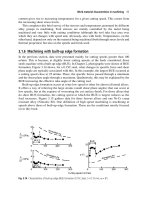
ments for level can be made. The baseplate should be leveled in the lon-
gitudinal or axial direction first, as shown in Figure 3-43, and then in the
transverse direction, as shown in Figure 3-44.
Conventional Grouting Method
Using the conventional method for installing a pregrouted baseplate is
no different from the first pour of a two-pour grout procedure. After the
concrete foundation has been chipped and cleaned, and the baseplate has
been leveled, grout forms must be constructed to hold the grout (Figure
3-45). To prevent trapping air under the prefilled baseplate, all the grout
Machinery Foundations and Grouting 119
material must be poured from one side. As the grout moves under the base-
plate, it pushes the air out. Because of this, the grout material must have
good flow characteristics. To assist the flow, a head box should be con-
structed and kept full during the grouting process.
Hydraulic Lift of a Pregrouted Baseplate
It is important when using a head box that the pregrouted baseplate is
well secured in place. The jack bolt and anchor bolt system must be tight,
and the anchor bolt nut should be locked down to the equivalent of 30 to
45 ft-lbs.
The bottom of a pregrouted baseplate provides lots of flat surface area.
The specific gravity of most epoxy grout systems is in the range of 1.9 to
2.1. Large surface areas and very dense fluids create an ideal environment
for buoyancy. Table 3-1 shows the inches of grout head necessary to begin
lifting a pregrouted American National Standards Institute (ANSI) base-
plate. During the course of a conventional grouting procedure, it is very
common to exceed the inches of head necessary to lift a pre-filled base-
plate. For this reason, it is very important to assure that the baseplate in
120 Machinery Component Maintenance and Repair
Figure 3-43. Field leveling in axial direction.
locked down. As a point of interest, the whole range of American Petro-
leum Institute (API) baseplates listed in Appendix M of API 610 can be
lifted with 9 inches of grout head.
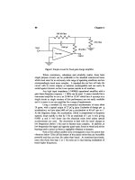
Baseplate Stress Versus Anchor Bolt Torque
With the necessity of using the jack bolt and anchor bolt system to lock
the pregrouted baseplate in position, it is important to determine if this
practice introduces stresses to the baseplate. It is also important to remem-
ber that any induced stresses are not permanent stresses, provided they
remain below the yield strength of the baseplate. The anchor bolts will be
loosened, and the jack bolts removed, after the grout has cured.
Machinery Foundations and Grouting 121
Figure 3-44. Field leveling in transverse direction.
An FEA analysis was performed on a pregrouted ANSI baseplate and
a pregrouted API baseplate. The baseplates that were analyzed had six
anchor bolt and jack bolt locations, used
3
/
4
≤ bolts, and was based on 45
ft-lbs and 100 ft-lbs of torque to the anchor bolts. The 100 ft-lbs of torque
was considered to be extremely excessive for leveling and locking down
a baseplate, but was analyzed as a worst-case scenario.
The peak local stress loads for 45 ft-lbs was 14,000 psi, and 28,000 psi
for 100 ft-lbs. Most baseplates are fabricated from ASTM A36 steel, which
has a yield stress of 36,000 psi. As Figure 3-46 shows, the stresses are very
localized and decay very rapidly. The result of the FEA analysis shows
that the effect of locking down the pregrouted baseplate does not induce
any detrimental stresses.
New Field Grouting Method for Pregrouted Baseplates
Conventional grouting methods for nonfilled baseplates, by their very
nature, are labor and time intensive. Utilizing a pregrouted baseplate with
122 Machinery Component Maintenance and Repair
Figure 3-45. Pregrout installation using conventional method.
conventional grouting methods helps to minimize some of the cost, but
the last pour still requires a full grout crew, skilled carpentry work, and
good logistics. To further minimize the costs associated with baseplate
installations, a new field grouting method has been developed for
pregrouted baseplates. This new method utilizes a low-viscosity, high-
strength epoxy grout system that greatly reduces foundation preparation,
grout form construction, crew size, and the amount of epoxy grout used
for the final pour.
While there may be other low-viscosity, high-strength epoxy grout
systems available on the market, the discussion and techniques that follow
are based on the flow and pour characteristics of Escoweld
®
7560. This
type of low viscosity grout system can be poured from
1
/
2
≤ to 2≤ depths,
has the viscosity of thin pancake batter, and is packaged and mixed in a
liquid container. As shown in Figure 3-47, this material can be mixed and
poured with a two-man crew.
Concrete Foundation Preparation
One of the leading conflicts on epoxy grout installations is the issue of
surface preparation of the concrete foundation. Removing the cement
lattice on the surface of the concrete is very important for proper bonding,
but this issue can be carried to far (Figure 3-48). Traditional grouting
methods require plenty of room to properly place the grout, and this
requires chipping all the way to the shoulder of the foundation. Utilizing
Machinery Foundations and Grouting 123
Figure 3-46. Stresses due to 45 ft-lbs anchor bolt preload.
a low-viscosity epoxy grout system greatly reduces the amount of con-
crete chipping required to achieve a proper installation.
The new installation method allows for the chipped area to be limited
to the footprint of the baseplate (Figure 3-49). A bushing hammer can be
used to remove the concrete lattice, and the required depth of the final
grout pour is reduced to
3
/
4
≤ to 1≤.
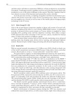
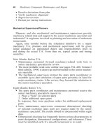
New Grout-forming Technique
With the smooth concrete shoulder of the foundation still intact, a very
simple “2 ¥ 4” grout form can be used (Figure 3-50). One side of the
simple grout form is waxed, and the entire grout form is sealed and held
in place with caulk (refer back to Figure 3-49). While the caulk is setting
up, a simple head box can be constructed out of dux seal. Due to the flow
characteristics of the low-viscosity epoxy grout, this head box does not
need to be very large or very tall.
The low viscosity epoxy grout is mixed with a hand drill, and all the
grout is poured through the head box to prevent trapping an air pocket
under the baseplate.
124 Machinery Component Maintenance and Repair
Figure 3-47. Mixing of low viscosity epoxy grout.
Machinery Foundations and Grouting 125
Figure 3-48. Chipping of concrete foundation.
Figure 3-49. New grout installation technique.
This new installation method has been used for both ANSI- and API-
style baseplates with great success. With this technique, field experience
has shown that a pregrouted baseplate can be routinely leveled, formed,
and poured with a two-man crew in 3 to 4 hours.
Field Installation Cost Comparison
The benefits of using a pregrouted baseplate with the new installation
method can be clearly seen when field installation costs are compared.
This comparison looks at realistic labor costs, and does not take any credit
for the elimination of repair costs associated with field installation prob-
lems, such as void repair and field machining.
Years of experience with grouting procedures and related systems point
to an average-size grout crew for conventional installations as eight men.
As of 2004, an actual man-hour labor cost of $45/hr can be easily defended
when benefits and overhead are included.
A cost comparison can be developed, based on the installation of a
typical API baseplate using epoxy grout, for the conventional two-pour
126 Machinery Component Maintenance and Repair
Figure 3-50. New grout-forming technique.
procedure and a pregrouted baseplate using the new installation method.
The following conditions apply:
Baseplate dimensions: 72≤¥36≤¥6≤
Foundation dimensions: 76≤¥40≤¥2≤ (grout depth)
Labor cost: $45/hr
Epoxy grout cost: $111/cubic ft
A baseplate with the listed dimensions can be pregrouted for $2,969.
This cost would include surface preparation, epoxy grout, surface grind-
ing, and a guaranteed inspection.
Table 3-2 shows a realistic accounting of time and labor for the instal-
lation of a typical API baseplate. The total installed cost for a conventional
two-pour installation is $6,259. The total installed cost for a pregrouted
baseplate, installed with the new installation method, is $4,194. That’s a
cost savings of almost 50 percent. More importantly, the installation is
void-free and the mounting surfaces are in tolerance.
Machinery Foundations and Grouting 127
Table 3-4
Lifting Forces for ANSI Baseplates
Grout Head Pressure Required to Lift a Pregrouted Baseplate
ANSI Type Baseplates
Epoxy
Base Grout Equalizing
Base Length Width Height Volume Weight Weight Pressure Grout
Size (in) (in) (in) (in
3
) (lbs) (lbs) (psi) Head (in)
139 39 15 4.00 2,340 93 169 0.45 6.22
148 48 18 4.00 3,456 138 250 0.45 6.22
153 53 21 4.00 4,452 178 322 0.45 6.22
245 45 15 4.00 2,700 108 195 0.45 6.22
252 52 18 4.00 3,744 150 271 0.45 6.22
258 58 21 4.00 4,872 195 352 0.45 6.22
264 64 22 4.00 5,632 225 407 0.45 6.22
268 68 26 4.25 7,514 283 544 0.47 6.47
280 80 26 4.25 8,840 332 639 0.47 6.47
368 68 26 4.25 7,514 283 544 0.47 6.47
380 80 26 4.25 8,840 332 639 0.47 6.47
398 98 26 4.25 10,829 407 783 0.47 6.47
Density of Grout 125 lbs/ft
3
Specific Gravity 2.00
Consider Prefilled Baseplates
It is possible to satisfy the concerns of both the project engineer and
the machinery engineer regarding rotating equipment installation. The
issues of first costs versus life-cycle costs can be reconciled with this new
128 Machinery Component Maintenance and Repair
Table 3-5
Cost Comparison for Two-Pour vs. New Method
Installation Labor Cost for Two-Pour Installation Labor Cost for Stay-Tru
Procedure System
Leveling of Baseplate Leveling of Base Plate
Millwright: 2 men ¥ 4 hr ¥ 520 Millwright: 2 men ¥ 1 hr ¥ 130
$65/h $65/hr
Forming of Baseplate Forming of Base Plate
4 men ¥ 4 hr ¥ $hr = 720 2 men ¥ 2 hr ¥ $hr = 180
First Pour
Grout Setup Time Grout Setup Time
8 men ¥ 1.0 hr ¥ $hr = 360 2 men ¥ 1.0 hr ¥ $hr = 90
Grout Placement Grout Placement
8 men ¥ 2.0 hr ¥ $hr = 720 2 men ¥ 2.0 hr ¥ $hr = 180
Grout Clean-up Grout Cleanup
8 men ¥ 1.0 hr ¥ $hr = 360 2 men ¥ 1.0 hr ¥ $hr = 90
Additional Cost Additional Cost
Forklift & driver; 1 hr ¥ $45 = 45 Wood Forming Materials = 50
Supervisor: 4.0 hr ¥ $hr = 180
Mortar Mixer = 100
Wood Forming Materials = 100
Second Pour
Grout Setup Time
8 men ¥ 1.0 hr ¥ $hr = 360
Grout Placement
8 men ¥ 2.0 hr ¥ $hr = 720
Grout Cleanup
8 men ¥ 1.0 hr ¥ $hr = 360
Additional Cost
Forklift & driver; 1 hr ¥ $45 = 45
Supervisor: 4.0 hr ¥ $hr = 180
Mortar Mixer = 100
LABOR COST 4,570 LABOR COST 670
ADDITIONAL COST 300 ADDITIONAL COST 50
GROUT COST 1,389.56 STAY-TRU COST 2,969
GROUT COST (7560) 505.3
TOTAL PER BASE $6,259.56 TOTAL PER BASE $4,194.30
approach to machinery field installations. As an added bonus, the term
repair can be eliminated from the grouting experience.
References
1. Lee, H. and Neville, K., Handbook of Epoxy Resins, McGraw-Hill,
New York, 1967, Page 1-1.
2. Adhesive Services Company Sales Literature and Advertising Copy
“The Foundation Report” as issued 1983 and 1984.
3. Renfro, E. M., “Five Years with Epoxy Grouts,” 19th annual meeting
of the Gas Compressor Institute, Liberal, Kansas, Preprint, April 4–5,
1972.
4. Bemiller, Clifford C., “Advances in Setting and Grouting Large Com-
pressor Units,” Cooper-Bessemer Company.
5. Barringer, P. and Monroe, T., “How to Justify Machinery Improvements
Using Reliability Engineering Principles,” Proceedings of the Sixteenth
International Pump Users Symposium, Turbomachinery Laboratory,
Texas A&M University, College Station, Texas, 1999.
6. Myers, R., “Repair Grouting to Combat Pump Vibration,” Chemical
Engineering, August 1998.
Bibliography
Exxon Chemical Company, “Escoweld 7505 Epoxy Grout,” OFI 68-251,
Houston, Texas.
Exxon Chemical Company, U.S.A., Product Publication Number OFCA-
74-1500, 1974, Page 12.
Renfro, E. M., “Foundation repair techniques,” Hydrocarbon Processing,
January, 1975.
Renfro, E. M., “Good foundations reduce machinery maintenance,”
Hydrocarbon Processing, January 1979.
Renfro, E. M., “Preventative design/construction criteria for turboma-
chinery foundations,” C9/83, Institute of Mechanical Engineers,
London, February 1983.
U.S. Department of Interior, Bureau of Reclamation, Concrete Manual,
eighth edition, 1975, Page 1.
Waddell, Joseph J., Concrete Construction Handbook, McGraw-Hill, New
York, 1968, Pages 6–12.
Machinery Foundations and Grouting 129
Appendix 3-A
Detailed Checklist for Rotating
Equipment: Horizontal Pump
Baseplate Checklist
130
Appendix 3-B
Specification for Portland
Cement Grouting of Rotating
Equipment
131
132 Machinery Component Maintenance and Repair
Machinery Foundations and Grouting 133
Appendix 3-C
Detailed Checklist for Rotating
Equipment: Baseplate Grouting
134
Machinery Foundations and Grouting 135
Appendix 3-D
Specifications for Epoxy
Grouting of Rotating Equipment
136
Machinery Foundations and Grouting 137
138 Machinery Component Maintenance and Repair
Machinery Foundations and Grouting 139