Machine Design Databook Episode 3 part 10 docx
Bạn đang xem bản rút gọn của tài liệu. Xem và tải ngay bản đầy đủ của tài liệu tại đây (674.63 KB, 40 trang )
Example: d ¼ 45 mm (1.8 in), k
D
¼ 785 N/mm
2
(80 kgf/mm
2
or 114000 psi)
q ¼ 0:2, forming height ¼ h ¼ 12:5mm:
B
¼ 196 N/mm
2
(20 kgf/mm
2
or 28500 psi).
Punch force ¼ P
F
¼ 1225 kN (125 tf) [C
0
-D
0
-E
0
] (Fig. 25-46).
Blank area ¼ F
B1
¼ 1600 mm
2
(2.46 in
2
)[A
0
-B
0
-C
0
].
Body cross-section of product ¼ Q
F
¼ 400 mm
2
(0.62 in
2
)[A
0
-L
0
-M
0
-N
0
].
The inside body height ¼ h
1
¼ 125 mm (5 in).
Work done: A
F
¼ 30896 m N (3150 mm tf or 22785 ft-lbf ) [E
0
-H
0
and G
0
-H
0
].
Press rating ¼ P
sat
¼ 1960 kN (200 tf) [H
0
-I
0
-K
0
].
10
1
20
8
2
5
4
6.3
1.6
2.5
3.15
1.25
Multiplication factor,
H,F,P
95 94 92 90 88 84 80 75 68 60 50 37
0.05 0.06 0.08
0.12 0.25 0.630.320.16
0.1 0.2 0.4 0.80.5
Degree of forming ∈, %
I
II
Cold-extruded, thickwalled hollow bodies
hollow bodies
Stamping
Solid and
Solid bodies
Cross-section ratio q
H,F
for extusion moulding and impact extrusion
Height ratio S
2
/ S
1
for stamping and cold working
π
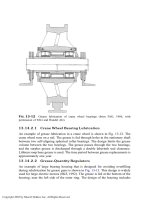
FIGURE 25-47 Determination of multiplication factor for impact extrusion and cold extrusion, and also for stamping and
coining
Courtesy: Heinrich Makelt, Die Mechanischen Pressen, Carl Hanser Verlag, Munich, German Edition, 1961 (Translated by R.
Hardbottle, Mechanical Presses, Edward Arnold (Publishers) 1968)
ELEMENTS OF MACHINE TOOL DESIGN
25.85
Downloaded from Digital Engineering Library @ McGraw-Hill (www.digitalengineeringlibrary.com)
Copyright © 2004 The McGraw-Hill Companies. All rights reserved.
Any use is subject to the Terms of Use as given at the website.
ELEMENTS OF MACHINE TOOL DESIGN
E
Speclflc compression
londing K
D
, kg/mm
2
C
onversion curve
for die area
Limit curve for rational pressworking
capacity utlllsation
B
C
A
X
A
X
II
IV
III
F
E
Blank diemeter d. mm
Stamping work A
p
, m.kg or mm.tonnes
Stamping volume V
stamp
, cm
3
5
8 12.5 20 31.5 50
80
125
10
5.3
8
10
12.5
15
20
25
31.5
40
50
65
12.5 16 20 100
80
63
50
40
200
315
500
400
250160
100
63
40
25
16
6.3
10
25
31.5
8000
6300
5000
4000
3150
2500
2000
1600
1250
1000
800
630
500
400
315
250
200
160
125
100
80
X — Projected die area F
p
, mm; Y — Stamping stroke h
p
, mm; Z — Stamping forc
e
50
63
80
100
125
160
200
250
315
C
G
H
Y
160
125
100
80
63
50
40
31.5
25
20
V
stamp
200
250
315
400
500
630
800
1000
1250
1600
2000
2500
4000
5000
6300
8000
10000
12500
3150
G
6.3
8
10
12.5
16
20
25
31.5
40
50
63
80
100
125
160
200
250
315
400
5
4
3.15
2.5
2
1.6
1.25
0.8
0.63
1
Y
I
D
lache F
p
d
P
P
F
P
h
P
s
2
s
1
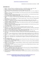
FIGURE 25-48 Chart for calculating stamping and coining
Courtesy: Heinrich Makelt, Die Mechanischen Pressen, Carl Hanser Verlag, Munich, German Edition, 1961 (Translated by R.
Hardbottle, Mechanical Presses, Edward Arnold (Publishers) 1968)
X- projected die area F
p
, mm; Y- stamping stroke h
p
, mm; Z, stamping force P
p
, tonnes.
Key to Fig. 25-49
Equations and Examples:
Forging temperature ¼ T ¼ 10008C.
Tensile strength of plain carbon steel ¼
B
¼ 588 N/mm
2
(60 kgf/mm
2
or 86000 lbf/in
2
[point B ] (Fig. 25-49).
Static deformation resistance ¼ k
Fg
¼ 49 N/mm
2
(5 kgf/mm
2
or 7100 lbf/in
2
) [point C of curve].
The deformation rate ¼ w ¼ "r=t(% sec) ¼ 500%/sec [point D].
The arithmetic proportions of upsetting ¼ "
h
¼ 4h=h
o
¼½1 À F
o
=F
1
100%.
The dynamic deformation resistance ¼ k
Fd
¼ 98 N/mm
2
(10 kgf/mm
2
or 14200 psi) [point E of the curve] (Fig. 25-49).
¼ 2k
Fg
where k
Fa
¼ static strength.
The diameter of non-circular upset or forged component is calculated from d
111
¼
ffiffiffiffiffiffiffiffiffiffiffiffiffiffiffiffiffi
ð4=ÞF
1
p
¼ 1:13
ffiffiffiffiffi
F
1
p
mm where F
1
¼ cross-
section after forming (upsetting surface).
The flash ratio ¼ b=s ¼ 4:8 (point F , scale 11).
The deformation resistance ¼ k
w
¼ 392 N/mm
2
(40 kgf/mm
2
or 57000 psi) [point G of the curve].
The upsetting force ¼ P
s
¼ 24516 kN (2500 tf) [point I of the curve]
A prescribed or theoretical upsetting or die diameter d
1
[D ¼ 280 mm (11 in)].
The corresponding upsetting or die area F
1
½F
tot
¼ 63000 mm
2
(96 in
2
) [point H ].
The maximum diameter D ¼ d
1
þ 2b of forged component
The crushed flash or the total cross-sectional area ¼ F
tot
¼ F
1
þ Ub where U ¼ periphery of crushed area.
The mass ratio ¼ L
s
=B
m
¼ 6:3 [point K ].
The maximum upsetting force ¼ P
max
¼ 30890 kN (3150 tf) [point L of the curve].
The upset path ¼ h ¼ 16 mm (0.65 in) [point M].
The upsetting work ¼ A
s
¼ 348134 mm N (35500 mm tf or 256665 ft-lbf) [line N-O ].
25.86 CHAPTER TWENTY-FIVE
Downloaded from Digital Engineering Library @ McGraw-Hill (www.digitalengineeringlibrary.com)
Copyright © 2004 The McGraw-Hill Companies. All rights reserved.
Any use is subject to the Terms of Use as given at the website.
ELEMENTS OF MACHINE TOOL DESIGN
Deformation rate
w, %/sec
H
am
m
ers
X
Y
Z
C
E
E
G
H
I
C
A
Materials testing machine
Static deformation strength K
Fs.
kg/mm
2
Deformation resistance, kg/mm
2
Max. upsetting work. tonnes
Upsetting work A
s
. m.kg
Upsetting and die diameter d
1
or D. mm
Upsetting and die area F
1
or F
tot
. mm
2
Die measurement
ratio L
s
/B
m
Pressworking capacity
at 25% speed Increase
Pressworking capacity
at 15% speed decrease
Tensile strength
σ
B
. kg/mm
2
High-percentage
Cr-Ni steels
(high-percentage
Cr steels)
High-percentage
Ni steels
Deformation
efficiency
C steels
C steels
Hydraulic prosses
I Free forging d
1
/h
1m
II Drop forging
b/s
III Form upsetting d
1
/2h
1m
Forging temperature T. …C
Dyn. deformation strength. kg/mm
2
Upsetting force P
s
. tonnes
II
III
IV
V
K
VI
I
25 16 10
10
16
25
800 900
1000 1150 1250 1400
6.3
6.3
4
4
2.5
2.5
2.5
2
.5
6
.3
1
6
1
1.6
2.5
4
6.3
10
16
25
40
63
1
6.3
16
40
100250
200500 mm 80 31.5 12.5 5
2.5
40
50
~50
~80
100
120
500
500
250
150
100
50
40
25
15
10
6.3
4
800
1250 2000
3150
5000
800
1250
2000
3150
5000
X — Explosion deformatuon; Y — High-
speed presses (V
eff
~ 0.53); Z — Longi-
tudinal mechanical presses (V
eff
~ 0) 125)
Upsetting path h to BDC on fininshed
forging. mm
Upsetting path h to BDC on upsetting. mm
500
400
315
250
200
200 × 10
3
160
125
125
100
80
80
50
31.5
20
12.5
63
B
m
50000
5000
1
6
00
500
160
50
5
(ueff. = 0.025 0.05 m/s)
(ueff. ~ 3.15 m
/s)
D
B
G
8
5
3.15
F
0.63
0.5
0.8
0.4
0.315
0.25
0.2
0.16
0.125
0.1
4
1
2.5
6
8.5
12
16
9
7
5.3
4
3
2.1
1.5
1
11.2
14
8.5
6.3
4.8
3.4
2.4
1.6
1
M
L
N
O
100 × 10
3
L
I
L
s
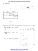
FIGURE 25-49 Chart for calculating hot upsetting and drop forging
Courtesy: Heinrich Makelt, Die Mechanischen Pressen, Carl Hanser Verlag, Munich, German Edition, 1961 (Translated by R.
Hardbottle, Mechanical Presses, Edward Arnold (Publishers) 1968)
ELEMENTS OF MACHINE TOOL DESIGN
25.87
Downloaded from Digital Engineering Library @ McGraw-Hill (www.digitalengineeringlibrary.com)
Copyright © 2004 The McGraw-Hill Companies. All rights reserved.
Any use is subject to the Terms of Use as given at the website.
ELEMENTS OF MACHINE TOOL DESIGN
The ratio of weights of two bars of same length whose
weights are W
1
¼
1
A
1
l and W
2
¼
2
A
2
l
The ratio of weights of two bars of same length
subjected to tensile load F
The ratio of weights of two bars of same length
subjected to torque M
t
The ratio of weights of two bars of same length
subjected to bending M
b
For specific stiffness (in tension)
For comparison of specific strength and stiffness/
rigidity of different section having equal cross
sectional area
DESIGN OF FRAMES, BEDS, GUIDES AND
COLUMNS:
For machine frames
For stiffening effect of reinforcing ribs
For characteristics of bending and torsional rigidities
of models of various forms
For variations in relative bending and torsional rigid-
ity for models of various forms
For effect of stiffener arrangement on torsional stiff-
ness of open structure
Refer to Table 25-64 for unit stiffness or specific stiff-
ness E=.
W
1
W
2
¼
1
A
1
l
2
A
2
l
¼
E
2
1
E
1
2
¼
E
2
=
2
E
1
=
1
ð25-169Þ
where E= is the unit stiffness or specific stiffness
Refer to Table 25-64, which gives E, and E= for
some machine tool structural materials
W
1
W
2
¼
nPLð
1
=
ut1
Þ
nPLð
2
=
ut2
Þ
¼
ut2
=
2
ut1
=
1
ð25-170Þ
where
ut
= is unit strength under tension
W
1
W
2
¼
2=3
ut
=
2
2=3
ut
=
1
ð25-171Þ
where
2=3
ut
= is an index of the ability of a material
to resist torsion and is known as unit
strength under torsion
W
1
W
2
¼
ð1=
b1
Þ
2=3
1
ð1=
b2
Þ
2=3
2
¼
2=3
b2
=
2
2=3
b1
=
1
ð25-172Þ
where
2=3
b
= is an index of the ability of a material
to resist bending and is known as the unit
strength under bending
Refer to Table 25-64.
Refer to Table 25-65.
Refer to Table 25-66.
Refer to Fig. 25-50.
Refer to Table 25-67.
Refer to Table 25-68.
Refer to Table 25-69.
Particular Formula
25.88 CHAPTER TWENTY-FIVE
Downloaded from Digital Engineering Library @ McGraw-Hill (www.digitalengineeringlibrary.com)
Copyright © 2004 The McGraw-Hill Companies. All rights reserved.
Any use is subject to the Terms of Use as given at the website.
ELEMENTS OF MACHINE TOOL DESIGN
For effect of aperture and cover plate design in static
and dynamic stiffness of box sections
For typical cross-sections of beds
For classification and identification of machine tools
For machine tools sliding guides, ball and roller
guides made of cast iron, steels and plastics
For design of spindle units in machine tools
For design of power screws and lead screws of
machine tools
For vibration and chattering in machine tools
For variable speed drives and power transmission
For lubrication of guides, spindles and other parts of
machine tools
TOOLING ECONOMICS (Adopted from Tool
Engineers Handbook)
Symbols:
a saving in labor cost per unit
C first cost of fixture
D annual allowance for depreciation, per cent
H number of years required for amortization of
investment out of earnings
I annual allowance for interest on investment, per
cent
Number of pieces required to pay for fixture
Economic investment in fixtures for given production
Number of years required for a fixture to pay for itself
Profit from improved fixture designs
Refer to Table 25-70.
Refer to Fig. 25-51A, B, C and D.
Refer to Table 25-72.
Refer to Tables and Figures from 25-66 to 25-71. In
addition to these, readers are advised to refer to
books and handbooks on machine tools. The design
of machine tool slideways, guides, beds, frames and
columns subjected to external forces are beyond the
scope of this Handbook.
Refer to Chapter 14 on ‘‘Design of shafts’’ in this
Handbook.
Refer to Chapter 18 on ‘‘Power screws and fasteners’’
in this handbook, and books on power screw design
of machine tools.
Refer to Chapter 22 on ‘‘Mechanical vibrations’’ in
this Handbook.
Refer to Chapter 23 on ‘‘Gears’’ and Chapter 25 on
‘‘Miscellaneous machine elements’’ in this Handbook.
Refer to Chapter 24 on ‘‘Design and bearings and
Tribology’’ in this Handbook and other books on
lubrication.
M annual allowance for repairs, per cent
N number of pieces manufactured per year
S yearly cost of setup
t percentage of overhead applied on labour saved
T annual allowances for taxes, per cent
V yearly operating profit over fixed charges
N ¼
C ðI þ T þD þ MÞþS
að1 þ tÞ
ð25-173Þ
C ¼
Nað1 þ tÞÀS
I þ T þD þM
ð25-174Þ
H ¼
C
Nað1 þ tÞÀCðI þ T þ MÞÀS
ð25-175Þ
V ¼ Nað1 þ tÞÀCðI þ T þD þ MÞÀS ð25-176Þ
Particular Formula
ELEMENTS OF MACHINE TOOL DESIGN
25.89
Downloaded from Digital Engineering Library @ McGraw-Hill (www.digitalengineeringlibrary.com)
Copyright © 2004 The McGraw-Hill Companies. All rights reserved.
Any use is subject to the Terms of Use as given at the website.
ELEMENTS OF MACHINE TOOL DESIGN
PROCESS—COST COMPARISONS:
Symbols:
c value of each piece, dollars
C
x
, C
y
total unit cost for methods Y and Z
respectively
d hourly depreciation rate for the first machine
(based on machine hours for the base years
period)
D hourly depreciation rate for the second
machine (based on machine hours for the base
years period)
k annual carrying charge per dollar of
inventory, dollar
l labor rate for the first machine, dollar
L lot size, pieces
labor rate for the second machine, dollar
m monthly consumption, pieces
N
t
total number of parts to be produced in a
single run
Number of parts for which the unit costs will be equal
for each of two compared methods Y and Z (‘‘break-
even point’’)
Total unit cost for methods Y
Total unit cost for method Z
Quantity of pieces at break-even point
Relatively simple formula for calculation of economic
lot size, pieces
MACHINING COST:
Machining time cost per work piece
Non-productive time cost per work piece
Tool change time cost per work piece
Tool cost per work piece
N
b
number of parts for which the unit costs will
be equal for each of two compared methods Y
and Z (break-even point)
p number of pieces produced per hour by the
first machine
P number of pieces produced per hour by the
second machine
P
y
unit tool process cost for method Y
P
z
unit tool process cost for method Z
Q quantity of pieces at break-even point
T
y
total tool cost for method Y
T
z
total tool cost for method Z
s setup hours required on the first machine
S setup hours required on the second machine
V ratio of machining time piece
N
b
¼
T
y
À T
z
P
z
À P
y
ð25-177Þ
C
y
¼
P
y
N
t
þ T
y
N
t
ð25-178Þ
C
z
¼
P
z
N
t
þ T
z
N
t
ð25-179Þ
Q ¼
pPðSL þ SD À sl ÀsdÞ
Pðl þ dÞÀpðL þDÞ
ð25-180Þ
L ¼
ffiffiffiffiffiffiffiffiffiffiffiffiffiffiffiffiffiffiffiffiffiffiffiffi
24mS
kcð1 þ mvÞ
s
ð25-181Þ
C
m
¼
t
m
R
60
ð25-182Þ
C
n
¼
t
L
þ
t
s
n
b
R
60
ð25-183Þ
C
c
¼
t
m
t
c
R
60t
1
ð25-184Þ
C
t
¼
C
t1
1 þ n
s
þ
t
sh
t
m
R
60t
1
ð25-185Þ
Particular Formula
25.90 CHAPTER TWENTY-FIVE
Downloaded from Digital Engineering Library @ McGraw-Hill (www.digitalengineeringlibrary.com)
Copyright © 2004 The McGraw-Hill Companies. All rights reserved.
Any use is subject to the Terms of Use as given at the website.
ELEMENTS OF MACHINE TOOL DESIGN
Total cost of machining
Total tool cost per workpiece
C
tot
¼ C
m
þ C
n
þ C
c
þ C
t
ð25-186Þ
C
n
¼ C
c
þ C
t
ð25-187Þ
where
t
m
¼ machining time per workpiece, min
t
L
¼ loading and unloading time per workpiece, min
t
s
¼ setting time per batch, min
t
t
¼ tool life, min
t
c
¼ tool charge time, min
t
sh
¼ tool sharpening time, min
R ¼ cost rate per hour
n
b
¼ number of batch
n
s
¼ number of resharpening
Particular Formula
ELEMENTS OF MACHINE TOOL DESIGN
25.91
Downloaded from Digital Engineering Library @ McGraw-Hill (www.digitalengineeringlibrary.com)
Copyright © 2004 The McGraw-Hill Companies. All rights reserved.
Any use is subject to the Terms of Use as given at the website.
ELEMENTS OF MACHINE TOOL DESIGN
TABLE 25–64
Unit stiffness/rigidity of some materials
Modulus of Modulus of
elasticity, E rigidity, G Poisson’s Density,
a
Unit weight,
b
ratio, Unit stiffness
Material GPa Mpsi GPa Mpsi Mg/m
3
kg/m
3
kN/m
3
lbf/in
3
lbf/ft
3
E=
Aluminum 69 10.0 26 3.8 0.334 2.69 2,685 26.3 0.097 167 2:62 Â10
6
Aluminum cast 70 10.15 30 4.35 2,650 26.0 0.096 166 2:66 Â10
6
Aluminum (all alloys) 72 10.4 27 3.9 0.320 2.80 2,713 27.0 0.10 173 2:68 Â10
6
Beryllium copper 124 18.0 48 7.0 0.285 8.22 8,221 80.6 0.297 513 1:54 Â10
6
Carbon steel 206 30.0 79 11.5 0.292 7.81 7,806 76.6 0.282 487 2:69 Â10
6
Cast iron, gray 100 14.5 41 6.0 0.211 7.20 7,197 70.6 0.260 450 1:42 Â10
6
Malleable cast iron 170 24.6 90 13.0 7,200 70.61 2:41 Â10
6
Inconel 214 31.0 76 11.0 0.290 8.42 8,418 83.3 0.307 530 2:57 Â10
6
Magnesium alloy 45 6.5 16 2.4 0.350 1.80 1,799 17.6 0.065 117 2:56 Â10
6
Molybdenum 331 48.0 117 17.0 0.307 10.19 10,186 100.0 0.368 636 3:31 Â 10
6
Monel metal 179 26.0 65 9.5 0.320 8.83 8,830 86.6 0.319 551 2 :06 Â 10
6
Nickel-silver 127 18.5 48 7.0 0.332 8.75 8,747 85.80 0.316 546 1:48 Â10
6
Nickel alloy 207 30.0 79 11.5 0.30 8.3 8,304 81.4 0.300 518 2:54 Â10
6
Nickel steel 207 30.0 79 11.5 0.291 7.75 7,751 76.0 0.280 484 2:72 Â10
6
Phosphor bronze 111 16.0 41 6.0 0.349 8.17 8,166 80.1 0.295 510 1:38 Â10
6
Steel (18-8), stainless 190 27.5 73 10.6 0.305 7.75 7,750 76.0 0.280 484 2:50 Â10
6
Titanium (pure) 130 15.0 4.47 4,470 43.8 0.16 279 2:37 Â10
6
Titanium alloy 114 16.5 43 6.2 0.33 6.6 6,600 2:60 Â10
6
Brass 106 15.5 40 5.8 0.324 8.55 8,553 83.9 0.309 534 1:26 Â10
6
Bronze 96 14.0 38 5.5 0.349 8.30 8,304 81.4 1:18 Â10
6
Bronze cast 80 11.6 35 5.0 8,200 80.0 1:00 Â10
6
Copper 121 17.5 46 6.6 0.326 8.90 8,913 87.4 0.32 2 556 1:38 Â10
6
Tungsten 345 50.0 138 20.0 18.82 18,822 184.6 1.89
Douglas fir 11 1.6 4 0.6 0.330 4.43 443 4.3 0.016 28 2:56 Â10
6
Glass 46 6.7 19 2.7 0.245 2.60 2,602 25.5 0.094 162 1:80 Â10
6
Lead 36 5.3 13 1.9 0.431 11.38 11,377 111.6 0.411 710 3:10 Â10
6
Concrete
(compression)
14–28 2.0–4.0 2.35 2,353 23.1 147 0:60 Â10
6
Wrought iron 190 27.5 70 10.2 7,700 76.0 2:50 Â10
6
Zinc alloy 83 12 31 4.5 0.33 6.6 0.24 415 1:18 Â10
6
Graphite 750 108.80 2.25 22.1 34:00 Â10
6
HTS Graphite/5208
epoxy
172 24.95 1.55 15.2 11:30 Â10
6
T50 Graphite 2011 Al 160 23.20 2.58 25.3 6:32 Â 10
6
Boron 380 55.11 2.5 44.1 11:00 Â10
6
Boron carbide, BC 450 65.28 2.4 22.5 19:20 Â10
6
Silicon carbide, SiC 560 81.22 3.2 31.4 17:80 Â10
6
Boron/5505 epoxy 207 30.07 1.99 19.5 8:40 Â10
6
Boron/6601 Al 214 31.03 2.60 25.5 8:20 Â10
6
Kelvar 49 130 18.85 1.44 14.1 9:20 Â10
6
Kelvar 49/resin 76 11.02 1.38 13.5 5:60 Â10
6
Silicon, Si 110 15.95 2.30 22.5 4:86 Â10
6
Wood (along fiber) 11–15.1 1.59–2.19 0.41–0.82 4.0–8.0 2.75–1:86 Â 10
6
Nylon 4 0.58 1.1 10.8 0:37 Â10
6
Paper 1–2 0.15–0.29 0.50 4.9 0.20–0:41 Â10
6
E Glass/1002 epoxy 39 5.65 1.80 17.6 2:22 Â10
6
a
, mass density.
b
, weight density; w is also the symbol used for unit weight of materials.
Source: K. Lingaiah and B. R. Narayana Iyengar, Machine Design Data Handbook, Volume I (SI and Customary Metric Units), Suma Publishers,
Bangalore, India and K. Lingaiah, Machine Design Data Handbook, Volume II, (SI and Customary Metric Units), Suma Publishers, Bangalore,
India, 1986.
25.92 CHAPTER TWENTY-FIVE
Downloaded from Digital Engineering Library @ McGraw-Hill (www.digitalengineeringlibrary.com)
Copyright © 2004 The McGraw-Hill Companies. All rights reserved.
Any use is subject to the Terms of Use as given at the website.
ELEMENTS OF MACHINE TOOL DESIGN
TABLE 25-65
Comparison of specific strength and Rigidity/Stiffness of different sections having equal cross sectional areas
(in Flexure)
Cross-section Area A
Distance
to farthest
point, c
Moment of
inertia I
Section
modulus
Z ¼ I=c
i ¼
I
A
2
w ¼
Z
A
3=2
I
I
a
Ã
Z
Z
a
Ã
F
D
0.785D
2
D
2
0.05D
4
0.1D
3
0.08 0.14 1 1
F
B
B
2
B
2
B
4
/12 B
3
/6 0.083 0.166 1.06 1.16
F
H
B
B
2
r
ðr ¼H=BÞ
H
2
B
4
r
3
/12 B
3
r
2
/6 0.083r 0:166
ffiffi
r
p
1.9 1.6
d
F
D
0.785D
2
(1À
2
)
ð ¼ d=DÞ
D
2
0:05D
4
ð1 À
4
Þ
0:1D
3
ð1 À
4
Þ
0:08
1 À
4
ð1 À
2
Þ
2
0:14
1 À
4
ð1 À
2
Þ
3=2
2.1 1.73
b
F
B
B
2
(1À)
ð ¼ b=BÞ
B
2
B
4
12
ð1 À
4
Þ
B
3
6
ð1 À
4
Þ
1 À
4
12ð1 À
2
Þ
2
1 À
4
6ð1 À
2
Þ
3=2
4.6 3.2
b
hH
F
B
b
F
B
hH
9.5 4.6
ELEMENTS OF MACHINE TOOL DESIGN
25.93
Downloaded from Digital Engineering Library @ McGraw-Hill (www.digitalengineeringlibrary.com)
Copyright © 2004 The McGraw-Hill Companies. All rights reserved.
Any use is subject to the Terms of Use as given at the website.
ELEMENTS OF MACHINE TOOL DESIGN
TABLE 25-66
Machine Frames
Simple frames and beds of horizontal machines
Simple frames and beds of vertical machines
Portal frames
Circular frames, housings
Frames of piston machines, banks of cylinders
Frames of conveying machines
Crane structures
TABLE 25-65
Comparison of specific strength and Rigidity/Stiffness of different sections having equal cross sectional areas
(in Flexure) (Cont.)
Cross-section Area A
Distance
to farthest
point, c
Moment of
inertia I
Section
modulus
Z ¼ I=c
i ¼
I
A
2
w ¼
Z
A
3=2
I
I
a
Ã
Z
Z
a
Ã
b
B
h
H
BHð1 ÀÞ
ð ¼ b=B;
¼ h=HÞ
H
2
BH
3
12
ð1 À
3
Þ
BH
2
6
ð1 À
3
Þ
0:083
1 À
3
ð1 ÀÞ
2
0:166
1 À
3
ð1 À Þ
3=2
F
b/2 b/2
B
hH
11 52
* Z
a
=section modulus of round solid section=
D
3
32
; I
a
=Moment of Inertia of round solid section=
D
4
64
.
Z/Z
a
and I/I
a
for solid and hollow stock having identical cross sectional area in flexure.
25.94
Downloaded from Digital Engineering Library @ McGraw-Hill (www.digitalengineeringlibrary.com)
Copyright © 2004 The McGraw-Hill Companies. All rights reserved.
Any use is subject to the Terms of Use as given at the website.
ELEMENTS OF MACHINE TOOL DESIGN
TABLE 25-67
Characteristics of Bending and Torsional Rigidities for Models of Various Forms
Model No. Model form
Relative
rigidity in
bending S
b
Relative
rigidity in
torsion S
t
Weight of
model G
S
b
G
S
t
G
1 (basic)
1.00 1.00 1.00 1.00 1.00
2a
1.10 1.63 1.10 1.00 1.48
2b
1.09 1.39 1.05 1.04 1.32
3
1.08 2.04 1.14 0.95 1.79
4
1.17 2.16 1.38 0.85 1.56
5
1.78 3.69 1.49 1.20 3.07
6
1.55 2.94 1.26 1.23 2.39
TABLE 25-66
Machine Frames (Cont.)
Baseplates
Boxes
Pillars, brackets, pedestals, hangers, etc.
Tables, slide blocks, carriages
Crossheads, slides, jibs
Lids and casings
Source: Courtesy: Dobrovolsky, V., etl., ‘‘Machine Elements’’, Mir Publishers, Moscow, 1974.
ELEMENTS OF MACHINE TOOL DESIGN 25.95
Downloaded from Digital Engineering Library @ McGraw-Hill (www.digitalengineeringlibrary.com)
Copyright © 2004 The McGraw-Hill Companies. All rights reserved.
Any use is subject to the Terms of Use as given at the website.
ELEMENTS OF MACHINE TOOL DESIGN
TABLE 25-28
Variations in Relative Bending and Torsional Rigidity for Models of Various Forms
Relative rigidity in bending Relative rigidity in torsion
Model No.
Relative weight of
box-like section With ribs
With thicker
walls With ribs
With thicker
walls
1 (basic) 1.00 1.00 1.00 1.00 1.00
2a 1.10 1.10 1.15 1.63 1.18
2b 1.05 1.09 1.10 1.39 1.10
3 1.14 1.08 1.16 2.04 1.21
4 1.38 1.17 1.29 2.16 1.40
5 1.49 1.78 1.30 3.69 1.46
6 1.26 1.55 1.19 2.94 1.24
Source: Courtesy: Dobrovolsky, V., etl., ‘‘Machine Elements’’, Mir Publishers, Moscow, 1974.
TABLE 25-69
Effect of stiffner arrangement on torsional stiffness of open structure
4
Stiffener arrangement
Relative torsional
stiffness
Relative
weight
Relative torsional
stiffness per
unit weight
1
1.0 1.0 1.0
2
1.34 1.34 1.0
3
1.43 1.34 1.07
4
2.48 1.38 1.80
5
3.73 1.66 2.25
25.96 CHAPTER TWENTY-FIVE
Downloaded from Digital Engineering Library @ McGraw-Hill (www.digitalengineeringlibrary.com)
Copyright © 2004 The McGraw-Hill Companies. All rights reserved.
Any use is subject to the Terms of Use as given at the website.
ELEMENTS OF MACHINE TOOL DESIGN
TABLE 25-70
Effect of aperture and cover plate design on static and dynamic stiffness of box section
3
Relative stiffness about
Relative natural frequency of
vibrations about
Relative damping of
vibrations about
X-X Y-Y Z-Z X-X Y-Y Z-Z X-X Y-Y Z-Z
X
Y
100 100 100 100 100 100 100 100 100
X
Y
85 85 28 90 87 68 75 89 95
X
Y
89 89 35 95 91 90 112 95 165
X
Y
91 91 41 97 92 92 112 95 185
ELEMENTS OF MACHINE TOOL DESIGN
25.97
Downloaded from Digital Engineering Library @ McGraw-Hill (www.digitalengineeringlibrary.com)
Copyright © 2004 The McGraw-Hill Companies. All rights reserved.
Any use is subject to the Terms of Use as given at the website.
ELEMENTS OF MACHINE TOOL DESIGN
Factors
Profile I
ben
I
tors
A
I
ben
A
I
tors
A
11111
1.17 2.16 1.38 0.85 1.56
1.55 3 1.26 1.23 2.4
1.78 3.7 1.5 1.2 2.45
FIGURE 25-50 Stiffening effect of reinforcing ribs.
(a) (b) (c) (d)
FIGURE 25-51A Typical cross-sections of beds.
55
55
Male parts
Female parts
(a) (b) (c) (d)
FIGURE 25-51B Principal shapes of sliding guides. (a) flat
ways; (b) prismatic ways; (c) dovetail ways; (d) cylindrical
(bar-type) ways.
P
P
(a) (b)
FIGURE 25-51C Sliding guides. (a) closed type; (b) open
type.
25.98 CHAPTER TWENTY-FIVE
Downloaded from Digital Engineering Library @ McGraw-Hill (www.digitalengineeringlibrary.com)
Copyright © 2004 The McGraw-Hill Companies. All rights reserved.
Any use is subject to the Terms of Use as given at the website.
ELEMENTS OF MACHINE TOOL DESIGN
P
x
P
x
P
x
P
x
P
x
(a)
(b)
(a) ope
n
type
;
(b) closed type
P
x
P
H
P
H
P
H
P
H
P
H
Z
Z
Z
Z
Z
Z
P
P
P
P
P
y
y
y
P
45”
COS45”
45”
45”
45”
45”
y
2r
2r
2r
2r
2r
2r
2r
FIGURE 25-51D Rolling guides. (a) open type; (b) closed type.
TABLE 25-71
Traversing Force Calculations – Typical Cases
Type of ways r
eq
.cm Traversing force Q. kgf
1
y
45
2r
2r cos 45
P
x
P
z
r
1:5
Q ¼ P
x
þ 3T
0
þ
1:5
r
f
r
P
P ¼ P
2
þ G
1
þ G
2
2
45
P
x
P
z
2r
y
r
1:4
Q ¼ P
x
þ 4T
0
þ
1:4
r
f
r
P
3
2r
z
y
P
x
P
r
1:5
Q ¼ P
x
þ 2T
0
þ
1:5
r
f
r
P
4
2r
z
y
45
P
x
P
p
P
p
P
r
2:8
Q ¼ P
x
þ 4T
0
þ
2:8
r
f
r
P
P
2r
z
y
45
P
x
P
p
P
p
P
2r
45
z
y
P
x
P
p
P
p
P
Q ¼ P
x
þ 2T
0
þ
2:8
r
f
r
P
P
Notes: 1. The coefficient of rolling friction f
r
¼ 0:001 for ground steel ways and f
r
¼ 0:0025 for scrape d cast iron ways. The initial friction force,
referred to one separator, T
0
¼ 0:4 kgf:
2. Because of the low value of the friction forces, a simplified arrangement has been accepted in which the ways are subject only to the feed force P
x
,
vertical component P
x
of the cutting force, table weight G
1
and workpiece weight G
2
. The tilting moments, force P
p
and the components of the
traversing force are not taken into account.
3. In the type 4 ways only the feed force P
x
and the preload force P
p
are taken into consideration.
ELEMENTS OF MACHINE TOOL DESIGN 25.99
Downloaded from Digital Engineering Library @ McGraw-Hill (www.digitalengineeringlibrary.com)
Copyright © 2004 The McGraw-Hill Companies. All rights reserved.
Any use is subject to the Terms of Use as given at the website.
ELEMENTS OF MACHINE TOOL DESIGN
G
(c)
fA
fB
P
x
P
z
X
p
X
c
X
A
X
B
X
C
Q
x
Z
Q
Q
z
P
x
x
P
y
X
Q
z
O
β
B
cos
β
B
cos
β
A
sin
α
fB
fA
fC
Y
O
G
Acos
α
C
fC
(a)
(C)
(C)
(b)
(d)
C
I
I
II
I
L
c
y
c
y
G
y
c
Z
p
y
p
P
z
P
y
y
y
Q
d
1
Q
z
A
B
A
z
β
α
α
a
b
FIGURE 25-52 Forces acting on the Slidways of a Lathe – A Typical Case
Source: Courtesy: Acherkan, N., ‘‘Machine Tool Design’’, Mir Publishers Moscow, 1968.
25.100 CHAPTER TWENTY-FIVE
Downloaded from Digital Engineering Library @ McGraw-Hill (www.digitalengineeringlibrary.com)
Copyright © 2004 The McGraw-Hill Companies. All rights reserved.
Any use is subject to the Terms of Use as given at the website.
ELEMENTS OF MACHINE TOOL DESIGN
Description Symbol
Shafts
Shafts coupling:
Closed
Closed with over-load
protection
Flexible
Universal
Telescopic
Floating
Toothed
Parts mounted on shafts:
Freely mounted
Sliding on feather
Engaged with sliding key
Fixed
Plain bearings:
Radial
Single-direction thrust
Two-direction thrust
Antifriction bearings:
Radial
Single angular-contact
Duplex angular contact
Description Symbol
Belt drives:
Open flat belts
Crossed flat belts
V-belts
Chain drive
Toothed gearing:
Spur or helical gears
Bevel gears
Spiral (crossed helical) gears
Worm gearing
Back-and-pinion gearing
TABLE 25-72
Classification and Identification code of Machine Tools – Kinematic Diagram
ELEMENTS OF MACHINE TOOL DESIGN 25.101
Downloaded from Digital Engineering Library @ McGraw-Hill (www.digitalengineeringlibrary.com)
Copyright © 2004 The McGraw-Hill Companies. All rights reserved.
Any use is subject to the Terms of Use as given at the website.
ELEMENTS OF MACHINE TOOL DESIGN
Description Symbol
Nut on power screw:
Solid nuts
Split nuts
Clutches:
Single-direction jaw clutches
Spindle noses:
Centre type
Chuck type
Bar type
Drilling
Boring spindles with faceplates
Two-direction jaw clutches
Cone clutches
Single disk clutches
Twin disk clutches
TABLE 25-72
Classification and Identification code of Machine Tools – Kinematic Diagram (Cont.)
Description Symbol
Single-direction overrunning
clutches
Two-direction overrunning
clutches
Brakes:
Cone
Shoe
Band
Disk
Milling
Grinding
Electric motors:
On feet
Flange-mounted
Built-in
Source: Courtesy: Acherkan, N., et1., ‘‘Machine Tool Design’’, Moscow, 1968.
25.102 CHAPTER TWENTY-FIVE
Downloaded from Digital Engineering Library @ McGraw-Hill (www.digitalengineeringlibrary.com)
Copyright © 2004 The McGraw-Hill Companies. All rights reserved.
Any use is subject to the Terms of Use as given at the website.
ELEMENTS OF MACHINE TOOL DESIGN
REFERENCES
1. Lingaiah, K., Machine Design Data Handbook, McGraw-Hill Publishing Company, New York, 1994.
2. Lingaiah, K., Machine Design Data Handbook, Vol. I, Suma Publishers, Bangalore, India, 1986.
3. Merchant, M. E., Trans. Am. Soc. Mech. Engrs., 66, A-168, 1944.
4. Ernst, H., and M. E. Merchant, Chip Formation, Friction and Finish, Cincinneti Milling, Machine Company,
USA.
5. American Society of Tool and Manufacturing Engineers (ASTME), Tool Engineers Handbook,2
nd
ed.,
F. W. Wilson, Editor, McGraw-Hill Book Publishing Company, New York, 1959.
6. Cyril Donaldson, George H. Lecain and V.C. Goold, Tool Design, Tata-McGraw-Hill Publishing Company
Ltd., New Delhi, India, 1976.
7. Frank W. Wilson, Editor-in-Chief, American Society of Tool and Manufacturing Engineers (ASTME),
Fundamentals of Tool Design, Prentice Hall, New Delhi, India, 1969.
8. Kuppuswamy, G., Center for Continuing Education, Department of Mechanical Engineering, Indian Insti-
tute of Technology, Madras, India, August 12, 1987.
9. Sen, G. C., and A. B. Bhattacharyya, Principles of Machine Tools, New Central Book Agency, (P) Ltd.,
Calcutta, India, 1995.
10. Geoffrey Boothroyd, Fundamentals of Metal Machining and Machine Tools, McGraw-Hill Publishing Com-
pany, New York, 1975.
11. Koenigsberger, F., Design Principles of Metal Cutting Machine Tools, the MacMillan Company, New York,
1964.
12. Shaw, M. C., and C. J. Oxford, Jr., (1) ‘‘On the Drilling Metals’’ (2) ‘‘The Torque and Thrust in Milling’’, Trans.
ASME., 97:1, January 1957.
13. Hindustan Machine Tools, Bangalore, Production Technology, Tata-McGraw-Hill Publishing Company Ltd.,
New Delhi, India, 1980.
14. Central Machine Tool Institute, Machine Tool Design Handbook, Bangalore, India, 1988.
15. Acherkan, A., General Editor, V. Push, N. Ignatyev, A. Kakoilo, V. Khomyakov, Y. U. Mikheyev, N.
Lisitsyn, A. Gavryushin, O. Trifonov, A. Kudryashov, A. Fedotyonok, V. Yermakov, V. Kudinov, Machine
Tool Design, Vol. 1 to 4, Mir Publishers, Moscow, 1968-69.
16. Milton C. Shaw, Metal Cutting Principles , Clarendon Press, Oxford, 1984.
17. Martelloti, M. E., Trans. Am. Soc. Mech. Engrs., 63, 677, 1941.
18. Kovan, V. M., Technology of Machine Building, Mashgiz, Moscow, 1959.
19. Basu, S. R., and D. K. Pal, Design of Machine Tools ,2
nd
ed., Oxford and IBH Publishing Company, New
Delhi, 1983.
20. Heinrich Makelt, Die Mechanischen Pressen, Carl Hanser Verlag Muchen, 1961 (in German) Translated to
English by R. Hardbottle, Mechanical Presses, Edward Arnold (Publishers) Ltd., 1968.
21. Dobrovolsky, K. Zablonsky, S. Mak, Radchik, L. Erlikh, Machine Elements, Mir Publishers, Moscow, 1968.
22. Rivin, E. I., Stiffness and Damping in Mechanical Design, Marcel Dekker, Inc., New York, 1999.
23. Machine Tool Design and Numerical Control.
24. Chernov, N., Machine Tools, Translated from Russian to English by Falix Palkin, Mir Publishers, Moscow,
1975.
25. Greenwood, D. C., Engineering Data for Product Design, McGraw-Hill Publishing Company, New York,
1961.
ELEMENTS OF MACHINE TOOL DESIGN 25.103
Downloaded from Digital Engineering Library @ McGraw-Hill (www.digitalengineeringlibrary.com)
Copyright © 2004 The McGraw-Hill Companies. All rights reserved.
Any use is subject to the Terms of Use as given at the website.
ELEMENTS OF MACHINE TOOL DESIGN
CHAPTER
26
RETAINING RINGS AND CIRCLIPS
SYMBOLS
a acceleration of retained parts, m/s
2
(ft/s
2
or in/s
2
)
Ch actual chamfer, m (in)
Ch
max
listed maximum allowable chamfer, m (in)
C
F
conversion factor (refer to Table 26-1)
d depth of groove, m (in)
D shaft or housing diameter, m (in)
f frequency of vibration, cps
F
tg
allowable static thrust load on the groove wall, kN (lbf)
F
ig
allowable impact load on groove, kN (lbf)
F
rt
allowable static thrust load of the ring, kN (lbf)
F
ir
allowable impact load on a retaining ring, kN (lbf)
F
0
r
listed allowable assembly load with maximum corner radius or
chamfer, kN (lbf)
F
00
r
allowable assembly load when cornor radius or chamfer is less
than the listed, kN (lbf)
F
trr
allowable thrust load exerted by the adjacent part, kN (lbf)
F
sg
allowable sudden load an groove, kN (lbf)
F
sr
allowable sudden load on ring, kN (lbf)
l distance of the outer groove wall from the end of the shaft or
bore as shown in Fig. 26-2, m (in)
n factor of safety (about 2 to 4 may be assumed)
n
max
maximum safe speed, rpm
q reduction factor from Fig. 26-1.
r actual corner radius or chamfer, m (in)
r
max
listed maximum allowable corner radius, m (in)
t ring thickness, m (in)
T largest section of the ring, m(in)
w weight of retained parts, kN (lbf)
ðwaÞ
g
allowable vibratory loading on groove, kN (lbf)
ðwaÞ
r
allowable vibratory loading on ring, kN (lbf)
x
o
amplitude of vibration, m (in)
sy
tensile yield strength of groove material, Table 26-2, MPa (psi)
saw
maximum working stress of ring during expansion or
contraction of ring, MPa (psi)
s
shear strength of ring material, MPa (psi) (refer to Table 26-3)
coefficient of friction between ring and retained parts whichever
is the largest.
26.1
Downloaded from Digital Engineering Library @ McGraw-Hill (www.digitalengineeringlibrary.com)
Copyright © 2004 The McGraw-Hill Companies. All rights reserved.
Any use is subject to the Terms of Use as given at the website.
Source: MACHINE DESIGN DATABOOK
Note: and with subscript s designates strength properties of material used in
the design which will be used and observed throughout this Machine Design Data
Handbook. Other factors in performance or in special aspects are included from
time to time in this chapter and, being applicable only in their immediate context
are not given at this stage.
RETAINING RINGS AND CIRCLIPS:
(Figs. 26-1 to 26-28 and Tables 26-1 to 26-13)
Load Capacities of Retaining Rings:
Allowable static thrust load on the groove
Allowable static thrust load on ring which is subject
to shear
The allowable thrust load exerted by adjacent part
Allowable assembly load when the corner radius or
chamfer is less than the listed (F
00
r
< F
0
r
)
Dynamic Loading:
Allowable sudden load on ring
Allowable sudden load on groove
Allowable vibration loading on ring
Allowable vibration loading on groove
Acceleration of retained parts for harmonic oscillation
Allowable impact loading on groove
Allowable impact loading on ring
An empirical formula for maximum safe speed with
standard types of rings
F
tg
¼
C
F
Dd
sy
nq
ð26-1Þ
F
r
¼
C
F
Dt
s
n
ð26-2Þ
F
trr
saw
tT
2
18D
ð26-3Þ
F
00
r
¼
F
0
r
r
max
r
for radius ð26-4Þ
F
00
r
¼
F
0
r
Ch
max
Ch
for chamfer ð26-5Þ
F
sr
0:5F
r
ð26-6Þ
F
sg
0:5F
tg
ð26-7Þ
ðwaÞ
r
540F
r
a
ð26-8Þ
ðwaÞ
g
400F
tg
a
ð26-9Þ
a % 40x
o
f
2
ð26-10Þ
F
ig
¼ F
r
d=2 ð26-11Þ
F
ir
¼ F
r
t=2 ð26-12Þ
n
max
¼ 5000000=D where D in mm ð26-13Þ
n
max
¼ 20000=D where D in inches ð26-14Þ
Particular Formula
a
Note: Actual tests should be conducted because of repeated or cyclic condition.
26.2 CHAPTER TWENTY-SIX
RETAINING RINGS AND CIRCLIPS
Downloaded from Digital Engineering Library @ McGraw-Hill (www.digitalengineeringlibrary.com)
Copyright © 2004 The McGraw-Hill Companies. All rights reserved.
Any use is subject to the Terms of Use as given at the website.
For dimensions of external circlips—Type A—light
series
For dimensions of external circlips—Type A—heavy
series
For dimensions of internal circlips—Type B—light
series
For dimensions of internal circlips—Type B—Heavy
series
For dimensions of external circlip—Type C
For dimensions, allowable static thrust load, allow-
able corner radii, chamfers, housing diameter and
ring thickness of retaining rings—basic internal,
bowed internal, beveled internal, inverted internal,
double beveled internal, crescent-shaped, bowed E-
ring, reinforced, locking prong in grooved housing
and on grooved shafts, self locking and triangular
self locking ring etc.
For q reduction factor
Refer to Table 26-5 and Fig. 26-3.
Refer to Table 26-6 and Fig. 26-4.
Refer to Table 26-7 and Fig. 26-5.
Refer to Table 26-8 and Fig. 26-6.
Refer to Table 26-9 and Fig. 26-7.
Refer to Tables 26-10 to 26-13 and Figs. from 26-1 to
26-28.
Refer to Fig. 26-1.
FIGURE 26-1 Reduction curve
FIGURE 26-2 Edge margin
Particular Formula
TABLE 26-1
Conversion or correction factor C
F
for calculating F
r
and F
tg
for use in Eqs. (26-l) and (26-2)
Conversion or correction factor C
F
Ring type Ring: F
r
Groove: F
tg
Basic, bowed internal 1.2 1.2
Beveled internal 1.2 1.2
Double-beveled internal Use d=2 instead of d
Inverted internal, external 2/3 1/2
Basic, bowed external 1 1
Beveled external 1 1
Use d=2 instead of d
Crescent-shaped 1/2 1/2
Two-part interlocking 3/4 3/4
E-ring, bowed E-ring 1/3 1/3
Reinforced E-ring 1/4 1/4
Locking-prong ring See manufacturer’s 1.2
specifications
Heavy-duty external 1.3 2
High-strength radial 1/2 1/2
Miniature high-strength See manufacturer’s specifications
Thinner-gage high-strength 1/2 1/2
radial
RETAINING RINGS AND CIRCLIPS 26.3
RETAINING RINGS AND CIRCLIPS
Downloaded from Digital Engineering Library @ McGraw-Hill (www.digitalengineeringlibrary.com)
Copyright © 2004 The McGraw-Hill Companies. All rights reserved.
Any use is subject to the Terms of Use as given at the website.
TABLE 26-2
Tensile yield strength of groove material
Tensile yield strength,
sy
Groove material MPa lbf/in
2
Cold-rolled steel 310 45,000
Hardened steel (Rockwell C40) 1034 150,000
Hardened steel (Rockwell C50) 1380 200,000
Aluminum (2024-T4) 276 40,000
Brass (naval) 210 30,000
TABLE 26-3
Shear strength of ring material for use in Eq. (26-2)
Shear strength,
s
Ring Ring thickness
material Ring type mm (in) MPa lbf/in
2
Carbon
spring
steel (SAE
1060–
1090)
Basic, bowed, beveled, inverted
internal and external rings and
crescent-shaped
Up to and including
0.9 (0.035)
827 120,000
Double-beveled internal rings 1.07 (0.042) and over 1034 150,000
Heavy-duty external 0.90 (0.035) and over 1034 150,000
Miniature high-strength 0.510 (0.020) and
0.635 (0.025)
827 120,000
0.9 (0.035) and over 1034 150,000
Two-part interlocking, rein-
forced E-ring, high-strength
radial
All available 1034 150,000
Thinner high-strength radial All available 1034 150,000
E-ring, bowed E-ring 0.254 (0.010) and
0.380 (0.015)
690 100,000
0.635 (0.025) 827 120,000
0.9 (0.035) and over 1034 150,000
Locking-prong All available 896 130,000
Beryllium
copper
(CDA
17200)
Basic external 0.254 (0.010) and
0.380 (0.015)
758 110,000
sizes 12 through 23
Bowed external 0.380 (0.015) 758 110,000
sizes 18 through 23
E-ring 0.254 (0.010) 662 95,000
(size Â4 only)
26.4
RETAINING RINGS AND CIRCLIPS
Downloaded from Digital Engineering Library @ McGraw-Hill (www.digitalengineeringlibrary.com)
Copyright © 2004 The McGraw-Hill Companies. All rights reserved.
Any use is subject to the Terms of Use as given at the website.
TABLE 26-4
Maximum working stress of ring during expansion or contraction
Maximum allowable working stress,
saw
Ring material MPa lbf/in
2
Carbon spring steel (SAE 1075) 1724 250,000
Stainless steel (PH 15-7 Mo) 1724 250,000
Beryllium copper (CDA 17200) 1380 200,000
Aluminum (Alclad 7075-T6) 482 70,000
Courtesy: # 1964, 1965, 1973, 1981 Waldes Kohinoor, Inc., Long Island City, New York, 1985.
Edward Killian, ‘‘Retaining Rings’’, Robert O. Parmley, Editor-in-Chief ‘‘Mechanical Components
Handbook’’, McGraw-Hill Publishing Company, New York, USA.
TABLE 26-5
Dimensions for external circlips—type A—light series
FIGURE 26-3
All dimensions in millimeters
Circlip Shaft groove
Shaft Axial force
Dia sab Tol. on d
4
d
5
Tol. on m
1
m
2
n
d
1
h11 Max. Approx. d
3
d
3
Expanded Min. d
2
d
2
H13 Min. Min. N lbf
8 0.8 3.2 1.5 7.4 þ0.09 15.2
1:2
7.6 0.9 1.0 1180 265
9 1.7 8.4 À0.18 16.4 8.6 1360 305
þ0.15 0.6
10 9.3 17.6 9.6 1500 340
3.3 À0.30 1.5
11 1.8 10.2 18.6 10.5 2060 460
12 11 19.6 11.5 h11
1:11:2
0.75 2270 510
13 1 3.4 2 11.9 20.8 12.4 2940 660
26.5
RETAINING RINGS AND CIRCLIPS
Downloaded from Digital Engineering Library @ McGraw-Hill (www.digitalengineeringlibrary.com)
Copyright © 2004 The McGraw-Hill Companies. All rights reserved.
Any use is subject to the Terms of Use as given at the website.
TABLE 26-5
Dimensions for external circlips—type A—light series (Contd.)
All dimensions in millimeters
Circlip Shaft groove
Shaft Axial force
Dia sab Tol. on d
4
d
5
Tol. on m
1
m
2
n
d
1
h11 Max. Approx. d
3
d
3
Expanded Min. d
2
d
2
H13 Min. Min. N lbf
14 3.5 2.1 12.9
þ0:18
22
1:7
13.4 0.9 3190 720
15 3.6 13.8 À0.36 23.2 14.3 1.1 3920 880
16 3.7 2.2 14.7 24.4 15.2 4809 1080
17 3.8 2.3 15.7 25.6 16.2 1.2 5100 1150
18
3:9
2.4 16.5 26.8 17 6770 1520
19 2.5 17.5 27.8 18 7110 1600
20 4 2.6 18.5 29 19 1.5 7550 1700
21 4.1 2.7 19.5 30.2 20 7900 1780
22 1.2 4.2 2.8 20.5 31.4 21 1.3 1.4 8300 1860
24 4.4 3 22.2 33.8 2 22.9 9900 2230
25 23.2 þ0.21 34.8 23.9 1.7 10400 2335
26 4.5 3.1 24.2 À0.42 36 24.9 10790 2425
28 4.7 3.2 25.9 38.4 26.6 14710 3310
29 4.8 3.4 26.6 39.6 27.6 2.1 15300 3440
30 5 3.5 27.9 4.1 28.6 15890 3570
32 1.5 5.2 3.6 29.6 43.4 30.3 1.6 1.7 20590 4630
34 5.4 3.8 31.5 45.8 32.3 2.6 21770 4890
35 5.6 3.9 32.2 þ0.25 47.2 33 26180 5890
36 4 33.2 À0.25 48.2 34 3 27070 6085
38 5.8 4.2 35.2 50.6 36 h12 28540 6415
40 6 4.4 36.5 53 37.5 37360 8400
42 1.75 6.5 4.5 38.5 56 39.5 1.85 2 3.8 39230 8820
45 6.7 4.7 41.5 þ0.39 59.4 42.5 42170 9480
48 6.9 5 44.5 À0.78 62.8 2.5 45.5 45110 10140
50 6.9 5.1 45.8 64.8 47 55900 12565
52 7 5.2 47.8 67 49 58350 13120
55 7.2 5.4 50.8 70.4 52 61780 13890
56 2 7.3 5.5 51.8 71.6 53 2.15 2.3 62760 14110
58 5.6 53.9 73.6 55 65210 14660
60 7.4 5.8 55.8 þ0.46 75.8 57 4.5 67665 15210
62 7.5 6 57.8 À0.92 78 59 69625 15650
63 7.6 6.2 58.8 79.2 60 71100 15985
65 7.8 6.3 60.8 81.6 62 73550 16535
68 8 6.5 63.5 85 65 76880 17285
70 8.1 6.6 65.5 87.2 67 78940 17748
72 8.2 6.8 67.5 89.4 3 69 4.5 81395 18300
75 2.5 8.4 7 70.5 þ0.46 92.2 72 2.65 2.8 84336 18960
78 7.3 73.5 À0.92 96.2 75 88260 19840
80 8.6 7.4 74.5 98.2 76.5 h12 104930 23590
82 8.7 7.6 76.5 101 78.5 107870 24250
85 7.8 79.5 104 81.5 111795 25130
88 8.8 8 82.5 107 84.5 5.3 116700 26236
90 3 8.2 84.5 109 86.5 3.15 3.3 118660 26675
26.6 CHAPTER TWENTY-SIX
RETAINING RINGS AND CIRCLIPS
Downloaded from Digital Engineering Library @ McGraw-Hill (www.digitalengineeringlibrary.com)
Copyright © 2004 The McGraw-Hill Companies. All rights reserved.
Any use is subject to the Terms of Use as given at the website.