Machine Design Databook Episode 3 part 9 pptx
Bạn đang xem bản rút gọn của tài liệu. Xem và tải ngay bản đầy đủ của tài liệu tại đây (425.07 KB, 40 trang )
TABLE 25-34
Types and definitions of milling cutters (Cont.)
Arrangement
Type of teeth Application Size Appearance
Double
angle
Teeth on two
conical faces
Vee slots 458,608,908
Rounding Concave quarter
circle and flat
face
Corner radius
on edge
1.5–20 mm radius
Involute
gear
cutter
Teeth on two
involute curves
Involute gears Large range
ELEMENTS OF MACHINE TOOL DESIGN 25.45
Downloaded from Digital Engineering Library @ McGraw-Hill (www.digitalengineeringlibrary.com)
Copyright © 2004 The McGraw-Hill Companies. All rights reserved.
Any use is subject to the Terms of Use as given at the website.
ELEMENTS OF MACHINE TOOL DESIGN
TABLE 25-34
Types and definitions of milling cutters (Cont.)
Arrangement
Type of teeth Application Size Appearance
End mill Helical teeth at one
end and
circumferential
Light work,
slots,
profiling,
facing
narrow
surfaces
50 mm
TANGED END
TAPPED END
Parallel Shank
Tee slot Circumferential
and both sides
Tee slots in
machine
table
For bolts up to
24 mm
diameter
Dovetail On conical surface
and one end face
Dovetail
machine
slides
38 mm diameter,
458 and 608
25.46 CHAPTER TWENTY-FIVE
Downloaded from Digital Engineering Library @ McGraw-Hill (www.digitalengineeringlibrary.com)
Copyright © 2004 The McGraw-Hill Companies. All rights reserved.
Any use is subject to the Terms of Use as given at the website.
ELEMENTS OF MACHINE TOOL DESIGN
TABLE 25-34
Types and definitions of milling cutters (Cont.)
Arrangement
Type of teeth Application Size Appearance
Skid end
mill
Circumferential
and one end
Larger work
than end mill
40–160 mm
diameter
Cutter
Arbor
Cutting
saw (slot)
Circumferential
teeth
Cutting off or
slitting.
Screw
slotting
60–400 mm
diameter
Thick
Thin
Clearance
Concave-
convex
Curved teeth on
periphery
Radiusing 1.5–20 mm radius
Concave
Convex
Thread
milling
cutter
PARALLEL SHANK
TAPER SHANK
ELEMENTS OF MACHINE TOOL DESIGN 25.47
Downloaded from Digital Engineering Library @ McGraw-Hill (www.digitalengineeringlibrary.com)
Copyright © 2004 The McGraw-Hill Companies. All rights reserved.
Any use is subject to the Terms of Use as given at the website.
ELEMENTS OF MACHINE TOOL DESIGN
TABLE 25-35
Suggested feed per tooth for milling various materials, mm
Slotting and Form relieved
Face mills Helical mills side mills End mills cutters Circular saws
Materials to be milled HSS Carbide HSS Carbide HSS Carbide HSS Carbide HSS Carbide HSS Carbide
Cast iron
Soft (up to 160H
B
) 0.40 0.50 0.32 0.40 0.22 0.30 0.20 0.25 0.12 0.15 0.10 0.12
Medium (160 to 220H
B
) 0.32 0.40 0.25 0.32 0.18 0.25 0.18 0.20 0.10 0.12 0.08 0.10
Hard (220 to 320H
B
) 0.28 0.30 0.20 0.25 0.15 0.18 0.15 0.15 0.08 0.10 0.08 0.08
Malleable iron
a
0.30 0.35 0.25 0.28 0.18 0.20 0.15 0.18 0.10 0.10 0.08 0.10
Steel
Soft
a
(up to 160H
B
) 0.20 0.35 0.18 0.28 0.12 0.20 0.10 0.18 0.08 0.10 0.05 0.10
Medium (160 to 220H
B
) 0.15 0.30 0.12 0.25 0.10 0.18 0.08 0.15 0.05 0.10 0.05 0.08
Hard
a
(220 to 360H
B
) 0.10 0.25 0.08 0.20 0.08 0.15 0.05 0.12 0.05 0.08 0.03 0.08
Stainless
a
0.20 0.30 0.15 0.25 0.12 0.18 0.10 0.15 0.05 0.08 0.05 0.08
Brass and Bronze
Soft 0.55 0.50 0.45 0.40 0.32 0.30 0.28 0.25 0.18 0.15 0.12 0.12
Medium 0.35 0.30 0.28 0.25 0.20 0.18 0.18 0.15 0.10 0.10 0.08 0.08
Hard 0.22 0.25 0.18 0.20 0.15 0.15 0.12 0.12 0.08 0.08 0.05 0.08
Copper 0.30 0.30 0.25 0.22 0.18 0.18 0.15 0.16 0.10 0.10 0.08 0.05
Monel 0.20 0.25 0.18 0.20 0.12 0.15 0.10 0.12 0.08 0.08 0.05 0.08
Aluminum
a
0.55 0.50 0.45 0.40 0.32 0.30 0.28 0.25 0.18 0.15 0.12 0.12
a
Coolant to be used.
TABLE 25-36
Recommended cutting speeds for face and end milling with plain HSS and carbide milling cutters, m/min
Depth of cut
Roughing cut, 3 to 5mm Semi-finishing cut, 1.5 to 3 mm Finishing cut, below 1.5 mm
Material to
be milled HSS Carbide HSS Carbide HSS Carbide
Cast iron
Soft 25 68 30 80 36 105
Medium 15 50 25 68 30 80
Hard123816502068
Malleable Iron 25 68 30 80 36 105
Steel
a
:
Soft 28 120 32 150 40 180
Medium 22 100 28 120 32 135
Hard 15 75 20 90 25 105
Stainless 18 50 22 68 28 80
Brass
Average 30 75 45. 120 60 150
Soft yellow 60 120 90 180 120 240
Bronze 28 75 36 100 45 128
Copper 45 100 68 150 90 210
Monel 18 50 22 68 28 80
Aluminum
a
75 240 105 300 150 450
a
Coolant to be used
Note: Cutting speeds for 12% cobalt HSS should be about 25% to 50% higher than those shown for plain HSS.
Cutting speeds for cast alloy should be about 100% higher than those shown for plain HSS.
Above speeds should be reduced when milling work that has hard spots or when milling castings that are sandy.
25.48
Downloaded from Digital Engineering Library @ McGraw-Hill (www.digitalengineeringlibrary.com)
Copyright © 2004 The McGraw-Hill Companies. All rights reserved.
Any use is subject to the Terms of Use as given at the website.
ELEMENTS OF MACHINE TOOL DESIGN
TABLE 25-37
Feeds and speeds for hobbing
Feed, mm/rev. of blank
Hob
Module Roughing (single Roughing speeds,
Type of gear Material mm thread hob) (multithread hob) Finishing m/min
High speed reduction and step up Steel 1.5–8 1–1.5 1–1.5 0.8–1.25 9–25
Instrument Steel 0.4–1.25 0.5–1.5 Up to 3 0.5–1.0 25–60
Non-ferrous 0.4–1.25 1.0–1.5 Up to 3 0.5–1.0 25–60
Aircraft Steel 2.0–4.0 1.0–1.5 Up to 3 0.8–1.25 15–45
Machine tool and printing press Steel, C.I. 2.0–6.0 2.0–3.2 Up to 2.5 1.0–1.5 15–30
Non-ferrous 2.0–6.0 2.0–3.2 Up to 2.5 1.0–1.5 25–450
Automotive, including trucks
and tractors
Steel 1.5–8.10 2.0–3.2 Up to 2.5
Up to 2.0 (3 starts)
1.25–2.0 15–45
High quality industrial Steel 10.0–25.0 2.0–2.5 1.25–2.0 12–30
Cast iron 2.5–8.0 1.25–3.2
General industrial Steel 10.0–25.0 2.0–2.5 1.50–2.5 12–30
Cast iron 2.5–8.0 1.25–3.2
Splines Steel 1.25–3.0 1.25–1.5 0.50–1.75 l8–45
TABLE 25-38
Selection of milling cutters
Material Hardness
One-piece construction High-speed steel Cutting portion 760 HV (62 HRC) Min
Two-piece construction Shank portion
Cutting portion High speed steel Parallel shank 245 HV (21 HRC) Min
Body
Carbon steel with tensile strength
not less than 700MPa (190 HN)
Tang of Morse taper shank
320 HV (32HRC) Min
Note: The equivalent values within parentheses are approximate.
Recommendations for selection of milling cutters:
Tool Type N—For mild steel, soft cast iron and medium hard non-ferrous metals.
Tool Type H—For specially hard and tough materials.
Tool Type S—For soft and ductile materials.
Material to be cut Tensile strength, MPa Brinell hardness, H
B
Tool type
a
Carbon steel Up to 500 N or (S)
Above 500 up to 800 N
Above 800 up to 1000 N or (H)
Above 1000 up to 1300 H
Steel casting H
Gray cast iron Up to 180 N
Over 180 H
Malleability cast iron N
Copper alloy
Soft Sor(N)
Brittle Nor(H)
Zinc alloy Sor(N)
Aluminum alloy
Soft S
Medium/Hard Nor(S)
Aluminum alloy, age hardened
Low cutting speed N
High cutting speed S
Magnesium alloy Sor(N)
Unlaminated Nor(S)
a
Tool types within parentheses are non-preferred. Courtesy: IS 1830, 1971
25.49
Downloaded from Digital Engineering Library @ McGraw-Hill (www.digitalengineeringlibrary.com)
Copyright © 2004 The McGraw-Hill Companies. All rights reserved.
Any use is subject to the Terms of Use as given at the website.
ELEMENTS OF MACHINE TOOL DESIGN
TABLE 25-39
Dimensions for interchangeability of milling cutters and arbors with tenon drive
A
z
A
r
a
a
1
dφ
dφ
s×45
s×45
b
1
r
1
b
All dimensions in millimeters
Arbor Cutter
d
a
abr a
1
b
1
r
1
h6/H7 h11 H11 Max H11 H13 Max sz
b
5 3 2.0 0.3 3.3 2.5 0.6 0.3 0.075
8 5 3.5 0.4 5.4 4.0 0.6 0.4 þ 0.1 0.100
10 6 4.0 0.5 6.4 4.5 0.8 0.5 0.100
13 8 4.5 0.5 8.4 5.0 1.0 0.5 0.100
16 8 5.0 0.6 8.4 5.6 1.0 0.6 0.100
19 10 5.6 0.6 10.4 6.3 1.2 0.6 0.100
22 10 5.6 0.6 10.4 6.3 1.2 0.6 þ0.2 0.100
27 12 6.3 0.8 12.4 8.0 1.6 0.8 0.100
32 14 7.0 0.8 14.4 7.0 1.2 0.8 0.100
40 18 9.0 1.0 16.4 9.0 2.0 1.0 0.100
50 16 8.0 1.0 18.4 10.0 2.0 1.0 þ0.3 0.100
60 20 10.0 1.0 20.5 11.2 2.0 1.0 0.125
a
The tolerance on d is not applicable to gear hobs.
b
z ¼ maximum permissible deviation between the axial plane of the tenon and the axis of arbor of diameter d.
Courtesy: IS 6285-1971
25.50 CHAPTER TWENTY-FIVE
Downloaded from Digital Engineering Library @ McGraw-Hill (www.digitalengineeringlibrary.com)
Copyright © 2004 The McGraw-Hill Companies. All rights reserved.
Any use is subject to the Terms of Use as given at the website.
ELEMENTS OF MACHINE TOOL DESIGN
TABLE 25-40
Dimensions for interchangeability of milling cutters and milling arbors with key drive
dφ
C
C
C
1
C
1
a
r
KEYWAY IN CUTTER KEYWAY IN ARBOR
KEY
SECTION
a
a
b
s×45
r
1
All dimensions in millimeters
Key Keyway
d
a
a Tolerance Tolerance Tolerance Tolerance Tolerance
h6/H7 h9 b
b
S on Sa
c
C on CC
1
on C
1
r on rr
1
on r
1
822 26.7 8.9
10 3 3 0.16 þ0.09 3 8.2 11.5 0.4 0–0.1
13 3 3 0 3 11.2 0 14.6 þ0.1 0 0.16 0
16 4 4 4 13.2 0–0.1 17.7 0 0.6 –0.2 –0.08
19 5 5 5 15.6 21.1
22 6 6 0.25 0þ0.15 6 17.6 24.1 1.0
27 7 7 7 22.0 29.8 0 0.25 0
32 8 7 8 27.0 34.8 1.2 –0.3 –0.09
40 10 8 9 10 34.5 43.5
50 12 8 12 44.5 53.5 þ0.2 1.6
60 14 9 0.40 þ0.20 14 54.0 0–0.2 64.2 0 0–0.5 0.40 0–0.15
70 16 10 0 16 63.5 75.0 2.0
80 18 11 18 73.0 85.5
100 25 14 0.60 25 91.0 107.0 2.5 0.60 0–0.20
–0.20
a
The tolerance on diameter d is not applicable to gear hobs. IS: 6285, 1971.
b
Tolerance on thickness b of key: square, h9; rectangular, h11.
c
Tolerance on keyway width a: light drive fit, N9.
For keyway in arbor: running fit, H9; light drive fit, N9.
For keyway in cutter: C11
ELEMENTS OF MACHINE TOOL DESIGN 25.51
Downloaded from Digital Engineering Library @ McGraw-Hill (www.digitalengineeringlibrary.com)
Copyright © 2004 The McGraw-Hill Companies. All rights reserved.
Any use is subject to the Terms of Use as given at the website.
ELEMENTS OF MACHINE TOOL DESIGN
TABLE 25-41
American National Standard staggered teeth, T-slot milling cutters with Brown and Sharpe taper and Weldon shanks
(ANSI/ASME B94, 19, 1986)
With B. and S. With Weldon
taper
a
shank
Cutter Face Neck
Bolt diam., width, diam., Length Taper Length Diam.,
size DWNLNo. LS
1
4
9
16
16
64
17
64
——2
19
32
1
2
5
16
21
32
17
64
21
64
——2
11
16
1
2
3
8
26
32
21
64
13
32
——3
1
4
3
4
1
13
32
25
64
17
32
573
7
16
1
5
8
1
1
4
31
32
21
32
6
1
4
73
15
16
1
3
4
1
15
32
5
8
25
32
6
7
8
94
7
16
—
11
27
32
53
64
1
1
32
7
1
4
94
13
16
1
1
4
All dimensions are inches. All cutters are high-speed steel and only right-hand cutters are standard.
a
For dimensions of Brown and Sharpe taper shanks. See information given in standard Handbook. Tolerances: On D, þ0.000, À0.010 inch; on W,
þ0.000, À0.005 inch; on N, þ0.000, À0.005 inch, on L, Æ
1
16
inch; on S, À0.0001 to À0.0005 inch.
TABLE 25-42
American National Standard 60-degree single-angle milling cutters with Weldon shanks (ANSI/ASME B94, 19, 1985)
L
D
S
w
60
Diam., DS W L Diam., DS W L
3
4
3
8
5
16
2
1
16
1
7
8
7
8
13
16
3
1
4
1
3
8
5
8
9
16
2
7
8
2
1
4
11
1
16
3
3
4
All dimensions are in inches. All cutters are high-speed steel. Right-hand cutters are standard.
Tolerances: On D, 0.015 inch; on S, À0.0001 to À0.0005 inch; on W, 0.015 inch; and on L, Æ
1
16
inch.
25.52 CHAPTER TWENTY-FIVE
Downloaded from Digital Engineering Library @ McGraw-Hill (www.digitalengineeringlibrary.com)
Copyright © 2004 The McGraw-Hill Companies. All rights reserved.
Any use is subject to the Terms of Use as given at the website.
ELEMENTS OF MACHINE TOOL DESIGN
TABLE 25-43
American National Standard multiple flute, helical series end mills with Brown and Sharpe taper shanks
a
(ANSI/
ASME B94, 19, 1985)
L
w
D
Diam., DW L Taper No. Diam., DW L Taper No.
––––11
5
8
5
5
8
7
––––1
1
4
27
1
4
9
1
2
15
16
4
15
16
71
1
2
2
1
4
7
1
2
9
3
4
1
1
4
5
1
4
722
3
4
89
All dimensions are in inches. All cutters are high-speed steel. Right-hand cutters with right hand helix are standard. Helix angle is not less than 10
degrees.
No. 5 taper is standard without tang: Nos. 7 and 9 are standard with tang only.
Tolerances: On D, þ0.005 inch; on W, Æ
1
32
inch; and L, Æ
1
16
inch.
a
For dimensions of B. and S. taper shanks, see information given in standard handbook.
ELEMENTS OF MACHINE TOOL DESIGN 25.53
Downloaded from Digital Engineering Library @ McGraw-Hill (www.digitalengineeringlibrary.com)
Copyright © 2004 The McGraw-Hill Companies. All rights reserved.
Any use is subject to the Terms of Use as given at the website.
ELEMENTS OF MACHINE TOOL DESIGN
TABLE 25-44
American National Standard form relieved, concave, convex, and corner-rounding arbor-type cutters
a
(ANSI/ASME
B94, 19, 1985)
w
w
H
H
H
D
Concave Convex Corner - Rounding
D
C
C
w
R
D
Diameter C or radius R Diameter of hole H
Cutter Width W
Nom. Max. Min. diam. D
b
Æ:010
c
Nom. Max. Min.
Concave cutters
c
1
8
0.1270 0.1240 2
1
4
1
4
1 1.00075 1.00000
1
4
0.2520 0.2490 2
1
2
7
16
1 1.00075 1.00000
3
8
0.3770 0.3740 2
3
4
5
8
1 1.00075 1.00000
1
2
0.5040 0.4980 3
13
16
1 1.00075 1.00000
3
4
0.7540 0.7480 3
3
4
1
13
16
1
1
4
1.251 1.250
1 0.0040 0.9980 4
1
4
1
9
16
1
1
4
1.251 1.250
Convex cutters
d
1
4
0.2520 0.2480 2
1
2
1
4
1 1.00075 1.00000
3
8
0.3770 0.3730 2
3
4
3
8
1 1.00075 1.00000
1
2
0.5020 0.4980 3
1
2
1 1.00075 1.00000
3
4
0.7520 0.7480 3
3
4
3
4
1
1
4
1.251 1.250
1 1.0020 0.9980 4
1
4
11
1
4
1.215 1.250
Corner-rounding cutters
e
1
8
0.1260 0.1240 2
1
2
1
4
1 1.00075 1.00000
1
4
0.2520 0.2490 3
13
32
1 1.00075 1.00000
1
2
0.5020 0.4990 4
1
4
3
4
1
1
4
1.251 1.250
All dimensions in inches. All cutters are high-speed steel and are form relieved.
Right-hand corner rounding cutters are standard, but left-hand cutter for
1
4
inch size is also standard.
a
For key and keyway dimensions for these cutters, see standard handbook.
b
Tolerances on cutter diameters are þ
1
16
, À
1
16
inch for all sizes.
c
Tolerance does not apply to convex cutters.
d
Size of cutter is designated by specifying diameter C of circular form.
e
Size of cutter is designated by specifying radius R of circular form.
Source: Courtesy: ANSI/ASME B94, 19, 1985, Erik Oberg Editor Etd., Extracted from Machinery’s Handbook, 25th edition, Industrial Press,
N.Y., 1996.
25.54 CHAPTER TWENTY-FIVE
Downloaded from Digital Engineering Library @ McGraw-Hill (www.digitalengineeringlibrary.com)
Copyright © 2004 The McGraw-Hill Companies. All rights reserved.
Any use is subject to the Terms of Use as given at the website.
ELEMENTS OF MACHINE TOOL DESIGN
TABLE 25-45
American National Standard roughing and finishing gear milling cutters for gears with 14
1
2
degree pressure angles
(ANSI/ASME B94, 19, 1985)
H
H
D
ROUGHING FINISHING
D
Diametral Diam. of Diam. of Diametral Diam. of Diam. of Diametral Diam. of Diam. of
pitch cutter, D hole, H pitch cutter, D hole. H pitch cutter, D hole, H
Roughing gear milling cutters
18
1
2
235
1
4
1
1
2
53
3
8
1
1
1
2
71
3
4
44
3
4
1
3
4
63
1
2
1
1
4
16
1
2
1
3
4
44
1
4
1
1
4
73
3
8
1
1
4
2
1
2
6
1
8
1
3
4
54
3
8
1
3
4
83
1
4
1
1
4
35
5
8
1
3
4
53
3
4
1
1
4
–––
Finishing gear milling cutters
18
1
2
263
7
8
1
1
2
14 2
1
8
7
8
1
1
2
71
3
4
63
1
8
1162
1
8
7
8
26
1
2
1
3
4
73
3
8
1
1
4
18 2
7
8
2
1
2
6
1
8
1
3
4
83
1
2
1
1
2
20 2
7
8
35
5
8
1
3
4
82
7
8
1222
7
8
35
1
4
1
1
2
93
1
8
1
1
4
24 2
1
4
1
44
1
4
1
3
4
10 3 1
1
4
26 1
3
4
7
8
54
3
8
1
3
4
11 2
3
8
7
8
36 1
3
4
7
8
54
1
4
1
1
2
12 2
7
8
1
1
4
40 1
3
4
7
8
64
1
4
1
3
4
14 2
1
2
1–––
All dimensions are in inches.
All gear milling cutters are high-speed steel and are form relieved.
For keyway dimensions refer to standard handbook.
Tolerances: On outside diameter, þ
1
16
, À
1
16
inch; on hole diameter, through 1 inch hole diameter, þ0.00075 inch; over 1 inch and through 2 inch hole
diameter, þ0.0010 inch.
For cutter number relative to number of gear teeth, see standard handbook.
Roughing cutters are made with No. 1 cutter form only.
Source: Courtesy: ANSI/ASME B94, 19, 1985, Erik Oberg Editor Etd., Extracted from Machinery’s Handbook, 25th edition, Industrial Press,
N.Y., 1996.
ELEMENTS OF MACHINE TOOL DESIGN 25.55
Downloaded from Digital Engineering Library @ McGraw-Hill (www.digitalengineeringlibrary.com)
Copyright © 2004 The McGraw-Hill Companies. All rights reserved.
Any use is subject to the Terms of Use as given at the website.
ELEMENTS OF MACHINE TOOL DESIGN
TABLE 25-46
American National Standard regular, long and extra length, multiple-flute medium helix single-end end mills with
Weldon shanks (ANSI/ASME B94, 19, 1985)
S
L
w
D
AS INDICATED BY THE DIMENSIONS GIVEN BELOW, SHANK DIAM-
ETERS MAY BE LARGER, SMALLER, OR THE SAME AS THE CUTTER
DIAMATERS D.
Regular mills Long mills Extra long mills
Cutter
diam, DS W L N
a
SWLN
a
SWLN
a
1
4
a
3
8
5
8
2
7
16
4
3
8
1
1
4
3
1
16
4
3
8
1
3
4
3
9
16
4
5
16
a
3
8
3
4
2
1
2
4
3
8
1
3
8
3
1
8
4
1
8
23
1
4
4
3
8
a
3
8
3
4
2
1
2
4
3
8
1
1
2
3
1
4
4
3
8
2
1
2
4
1
4
4
7
16
3
8
12
11
16
4
1
2
1
3
4
3
3
4
4––––
1
2
3
8
12
11
16
4
1
2
244
1
2
354
9
16
1
2
1
3
8
3
3
8
4––––––––
3
8
1
2
1
3
8
3
3
8
4
5
8
2
1
2
4
5
8
4
5
8
46
1
8
4
11
16
1
2
1
5
8
3
5
8
4––––––––
3
4
1
2
1
5
8
3
5
8
4
3
4
35
1
4
4
3
4
46
1
4
4
7
8
5
8
1
7
8
46
7
8
3
1
2
5
3
4
4
7
8
57
1
4
4
1
5
8
1
7
8
46146
1
2
416 8
1
2
6
1
1
8
7
8
24
1
4
6146
1
2
6––––
1
1
4
7
8
24
1
4
6146
1
2
61
1
4
a
68
1
2
6
1
1
2
124
1
4
6146
1
2
6––––
1
1
4
1
1
4
24
1
2
61
1
4
46
1
2
6––––
1
1
2
1
1
4
24
1
2
61
1
4
46
1
2
61
1
4
810
1
2
6
1
3
4
1
1
4
24
1
2
61
1
4
46
1
2
6––––
21
1
4
24
1
2
81
1
4
46
1
2
8––––
All dimensions are in inches. All cutters are high-speed steel. Helix angle is greater than 19 degrees but not more than 39 degrees. Right-hand cutters
with right-hand helix are standard.
Tolerances: On D, þ0.003 inch; on S, 0.0001 to À0.0005 inch; on W, Æ
1
32
inch; on L, Æ
1
16
inch; N ¼ number of flutes.
a
In case of regular mill a left-hand cutter with left-hand helix is also standard.
Source: ANSI/ASME B94, 19, 1985, Erik Oberg Editor Etd., Extracted from Machinery’s Handbook, 25th edition, Industrial Press, N.Y., 1996.
25.56 CHAPTER TWENTY-FIVE
Downloaded from Digital Engineering Library @ McGraw-Hill (www.digitalengineeringlibrary.com)
Copyright © 2004 The McGraw-Hill Companies. All rights reserved.
Any use is subject to the Terms of Use as given at the website.
ELEMENTS OF MACHINE TOOL DESIGN
TABLE 25-47
American National Standard long length single-end and stub-, and regular length, double-end plain- and ball-end,
medium helix two-flute end mills with Weldon shanks (ANSI/ASME B94, 19, 1985)
S
L
B
w
w
D
C
D
L
S
w
C
D
Single end
Long length—plain end Long length—ball end
Diam., C
and DS B
a
WL S B
a
WL
1
4
3
8
1
1
2
5
8
3
1
16
3
8
1
1
2
5
8
3
1
16
5
16
3
8
1
3
4
3
4
3
5
16
3
8
1
3
4
3
4
3
5
16
3
8
3
8
1
3
4
3
4
3
5
16
3
8
1
3
4
3
4
3
5
16
1
2
1
2
2
7
32
14
1
2
2
1
4
14
5
8
5
8
2
23
32
1
3
8
4
5
8
5
8
2
3
4
1
3
8
4
3
8
1
4
3
4
3
11
32
1
5
8
5
3
8
3
4
3
3
8
1
5
8
5
3
8
114
31
32
2
1
2
7
1
4
152
1
2
7
1
4
Double end
Stub length—plain end Regular length—plain end Regular length—ball end
Diam., C
and DS WL S WL S WL
5
32
3
8
15
64
2
3
4
3
8
7
16
3
1
8
–––
1
4
3
8
3
8
2
7
8
3
8
1
2
3
1
8
3
8
1
2
3
1
8
5
16
–––
3
8
9
16
3
1
8
3
8
9
16
3
1
8
3
8
–––
3
8
9
16
3
1
8
3
8
9
16
3
1
8
7
16
–––
1
2
13
16
3
3
4
1
2
13
16
3
3
4
1
2
–––
1
2
13
16
3
3
4
1
2
13
16
3
3
4
5
8
–––
5
8
1
1
8
4
1
2
5
8
1
1
8
4
1
2
11
16
–––
3
4
1
5
16
5–––
3
4
–––
3
4
1
5
16
5
3
4
1
5
16
5
1–––11
5
8
5
7
8
11
5
8
5
7
8
All dimensions are in inches. All cutters are high-speed steel. Right-hand cutters with right hand helix are standard. Helix angle is greater than 19
degrees but not more than 39 degrees.
Tolerances: On C and D, þ0.003 inch; for single-end mills, À0.0015 inch for double end mills on S, À0.0001 to À0.0005 on W, Æ
1
32
inch; on L,
1
16
inch.
a
B is the length below the shank.
Source: Courtesy: ANSI/ASME B94, 19, 1985, Erik Oberg Editor Etd., Extracted from Machinery’s Handbook, 25th edition, Industrial Press,
N.Y., 1996.
ELEMENTS OF MACHINE TOOL DESIGN 25.57
Downloaded from Digital Engineering Library @ McGraw-Hill (www.digitalengineeringlibrary.com)
Copyright © 2004 The McGraw-Hill Companies. All rights reserved.
Any use is subject to the Terms of Use as given at the website.
ELEMENTS OF MACHINE TOOL DESIGN
TABLE 25-48
American National Standard Woodruff keyseat cutters
a
—shank-type straight teeth and arbor staggered teeth
(ANSI/ASME B94, 19, 1985)
L
DIAM.
w
w
D
D
1
—
2
H
Shank-type cutters
Nom. Nom. Nom.
Cutter diam. of Width of Length Cutter diam. of Width of Length Cutter diam. of Width of Length
No. cutter, D face, W overall, L No. cutter, D face, W overall, L No. cutter, D face, W overall, L
202
1
4
1
16
2
1
16
506
3
4
5
32
2
5
32
809 1
1
8
1
4
2
1
4
203
3
8
1
16
2
1
16
507
7
8
5
32
2
5
32
710 1
1
4
7
32
2
9
32
403
3
8
1
8
2
1
8
707
7
8
7
32
2
5
32
1010 1
1
4
5
16
2
5
16
404
1
2
1
16
2
1
16
807
7
8
1
4
2
1
4
1210 1
1
4
3
8
2
3
8
405
5
8
1
8
2
1
8
1008 1
5
16
2
5
16
812 1
1
2
1
4
2
1
4
505
5
8
5
32
2
1
32
1208 1
3
8
2
3
8
1212 1
1
2
3
8
2
3
8
Arbor-type cutters
Nom. Nom. Nom.
Cutter diam. of Width of Diam. of Cutter diam. of Width of Diam. of Cutter diam. of Width of Diam. of
No. cutter, D face, W a hole, H No. cutter, D face, W a hole, H No. cutter, D face, W hole, H
617 2
1
8
3
16
3
4
1012 2
3
4
5
16
116283
1
2
1
2
1
817 2
1
8
1
4
3
4
1222 2
3
4
3
8
118283
1
2
9
16
1
1217 2
1
8
3
16
3
4
1262 2
3
4
1
2
124283
1
2
3
4
1
822 2
3
4
1
4
1 1288 3
1
2
3
8
1––––
All dimensions are given in inches. All cutters are high-speed steel.
Shank type cutters are standard with right-hand cut and straight teeth. All sizes have
1
2
inch diameter straight shank. Arbor type cutters have
staggered teeth.
For Woodruff key and key-slot dimensions, see standard handbook.
Tolerances: Face width W for shank type cutters:
1
16
to
3
32
inch face þ0.0000, 0.0005:
3
16
to
7
32
, À0.002, 0.0007,
1
4
, À 0.0003, 0.0008,
5
16
, 0.0004, À0.0009,
3
8
, 0.0005, 0.001, À0.0008,
5
16
, À0.0004, À0.0009,
1
8
and over, À0.0005, À0.000 inch.
Hole size H, þ0.00075, À1:000 inch. Diameter D for shank type cutters;
1
8
, through
1
4
inch diameter, þ0 016, þ0.015,
7
8
through 1
1
8
, þ0.012, þ0.017;
1
1
4
through 1
1
2
, þ0.015, þ0.02 inch. These tolerances includes an allowance for sharpening. For arbor type cutters diameter D is furnished
1
32
inch
larger than bore and tolerance of þ0.002 inch applies to the over size diameter.
Source: Courtesy: ANSI/ASME B94, 19, 1985, Erik Oberg Editor Etd., Extracted from Machinery’s Handbook, 25th edition, Industrial Press,
N.Y., 1996.
25.58 CHAPTER TWENTY-FIVE
Downloaded from Digital Engineering Library @ McGraw-Hill (www.digitalengineeringlibrary.com)
Copyright © 2004 The McGraw-Hill Companies. All rights reserved.
Any use is subject to the Terms of Use as given at the website.
ELEMENTS OF MACHINE TOOL DESIGN
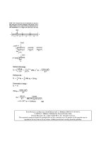
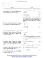
GRINDING
The tangential component of grinding force F
z
,
which constitutes the major value of grinding force
Fig. 25-26
Grinding
wheel
Work piece
F
x
F
R
v
w
F
y
= F
r
F
z
= F
t
v
g
FIGURE 25-26 Forces acting on a grinding wheel.
The chip thickness
The power required by the grinding wheel
Metal removal rate in case of transverse grinding
The power at the spindle
F
t
¼ K
m
st
v
w
v
g
ð25-123Þ
where
s ¼ feed rate, mm/rev
t ¼ thickness of material removed from job or
depth of cut, mm
v
w
¼ peripheral velocity of workpiece/job, m/min
v
g
¼ peripheral velocity of the grinding wheel, m/min
K
m
¼ specific resistance to grinding of the work
material, N/m
2
(Table 25-51)
F
y
¼ F
r
¼ radial component of the force in cylindri-
cal grinding operation, kN
F
x
¼ horizontal component of the force against the
feed, kN
F
z
¼ F
t
¼ vertical component of the force in the
cylindrical grinding operation, kN
t ¼
2pv
w
v
g
ffiffiffiffiffiffiffiffiffiffiffiffiffiffiffiffiffiffiffiffiffi
ðd
w
Æ d
g
Þs
d
g
d
w
s
ð25-124Þ
where
p ¼ pitch of grains, mm
d
w
¼ diameter of workpiece, mm
d
g
¼ diameter of grinding wheel, mm
þve sign for external grinding wheel, Àve for internal
grinding wheel
P ¼
F
t
ð¼F
z
Þv
g
1000
ð25-125Þ
where
F
t
¼ F
z
¼ tangential force on wheel, N
P ¼ power, W
v
g
¼ velocity of grinding wheel, mm/s
Q ¼
d
w
ts
1000
ð25-126Þ
P ¼ P
u
Q ð16-127Þ
where Q in cm
3
/min
Refer to Table 25-50 for P
u
.
Particular Formula
ELEMENTS OF MACHINE TOOL DESIGN
25.59
Downloaded from Digital Engineering Library @ McGraw-Hill (www.digitalengineeringlibrary.com)
Copyright © 2004 The McGraw-Hill Companies. All rights reserved.
Any use is subject to the Terms of Use as given at the website.
ELEMENTS OF MACHINE TOOL DESIGN
Energy per unit volume of material removed
Vertical boring:
The power required for boring
Centerless grinding:
The peripheral grinding wheel speed
Through feed rate
Metal removal rate from through feed grinding
Metal removal rate from plunge grinding
For the unit power
Power at the spindle
E ¼
P
bsv
g
ð25-128Þ
where
b ¼ width of cut, mm
s ¼ feed rate or depth of cut, mm/rev
E in J/mm
3
P ¼
iF
t
v
1000
ð25-129Þ
where
i ¼ number of heads
v ¼ cutting speed, mm/s
v
g
¼
d
w
n
1000 Â 60
ð25-130Þ
s
t
¼ d
r
n
r
sin ð25-131Þ
where
d
r
¼ diameter of regulating wheel, mm
n
r
¼ speed of regulating wheel, rpm
¼ regulating wheel inclination angle, deg
Q
t
¼
d
w
ts
t
1000
ð25-132Þ
where Q
t
in cm
3
/min
s
t
¼ through feed rate, mm/min
Q
p
¼
d
w
bs
p
1000
ð25-133Þ
where Q
p
in cm
3
/min
b ¼ width of cut plunge grinding, mm
s
p
¼ plunge in feed rate per minute ¼ðsn
w
Þ, mm/min
s ¼ plunge in feed rate per work revolution, mm/rev
n
w
¼ workpiece revolution per minute
Refer to Table 25-50.
P ¼ P
u
Q ð25-134Þ
Particular Formula
25.60 CHAPTER TWENTY-FIVE
Downloaded from Digital Engineering Library @ McGraw-Hill (www.digitalengineeringlibrary.com)
Copyright © 2004 The McGraw-Hill Companies. All rights reserved.
Any use is subject to the Terms of Use as given at the website.
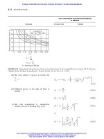
ELEMENTS OF MACHINE TOOL DESIGN
SHAPING (Fig. 25-27)
The force of cutting can be found by empirical
formula F
z
The approximate equation 1 expression for cutting
force F
z
for cast iron
The power consumption of shaping machine
The velocity of crank pin of r radius
The peripheral velocity of the sliding block
The peripheral velocity of the driving pin of the
rocker arm at point A.
The average velocity of ram at its middle position
during its stroke Fig. 25-28
F
z
¼ F
t
¼ 9:807C
p
kd
x
s
y
SI ð25-135aÞ
where F
z
in N
F
z
¼ F
t
¼ C
p
kd
x
s
y
Customary Metric Units ð25-135bÞ
where x, y, k and C
p
have the same values as in
lathe tools; F
z
in kgf
Equation (25-135) can be also used for the case of
planing machine.
F
z
¼ 1860ds
0:75
K SI ð25-136aÞ
F
z
¼ 190ds
0:75
K
Customary Metric Units ð25-136bÞ
P ¼
1
F
z
v
r
1000 Â60
ð25-137Þ
where v
r
¼ the the average velocity of ram in its
middle position during its stroke
v
1
¼
2rn
1000
ð25-138aÞ
v
2
¼ v
1
cosð À Þð25-138bÞ
v
ra
¼ v
2
R
Ma
ð25-138cÞ
v
r av
¼ n
Rl
R þðl=2Þ
ð25-138dÞ
where n in rpm
Particular Formula
F
x
F
y
F
R
F
z
= F
t
FIGURE 25-27 Forces acting on a shaping tool.
v
c max
O
M
b
α
γ
α−γ
(b)
(a)
c
d
v
1
v
2
v
ra
v
r
v
r max
l
l
L
A
B
C
K
p
R
a
FIGURE 25-28 Ram velocity diagram of a crank shaper.
ELEMENTS OF MACHINE TOOL DESIGN
25.61
Downloaded from Digital Engineering Library @ McGraw-Hill (www.digitalengineeringlibrary.com)
Copyright © 2004 The McGraw-Hill Companies. All rights reserved.
Any use is subject to the Terms of Use as given at the website.
ELEMENTS OF MACHINE TOOL DESIGN
The approximate/average velocity of ram
The maximum speed of ram for the average value of
cutting speed v
r
The maximum velocity of ram travel in the cutting
stroke when it is at ¼ ¼ 0
The minimum speed for the average value of cutting
speed v
r
The maximum velocity of ram travel during the return
stroke at ¼ 1808 and ¼ 0
The average cutting velocity v
r av
during travel 2l of
ram
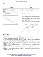
PRESS TOOLS
Punching (Figs. 25-29, 25-31 and 25-32):
Maximum shearing force or pressure to cut the
material
Work done
v
r
¼ v
ra
cos ð25-138eÞ
v
r
¼
2nRl cos
2
cosð À Þ
1000ð2R þ l cos Þ
ð25-138fÞ
n
max
¼ v
r
R þðl
min
=2Þ
R þ l
min
ð25-139aÞ
v
c max
¼
2nRl
1000ð2R þ lÞ
ð25-139bÞ
n
min
¼ v
r
R þðl
max
=2Þ
R À l
max
ð25-139cÞ
v
r
is a function of l, since and R are constants, i.e.
v
r
¼ f ðlÞ
v
r max
¼
2nRl
1000ð2R À lÞ
ð25-139dÞ
v
r av
¼
2ln
1000
ð25-139eÞ
where v
r av
in m/min
F
max
¼ pD
u
t for round hole ð25-140Þ
¼
u
tP for any other contour
W ¼ F
max
x ð25-141Þ
Particular Formula
Punch
Workpiece
Die
Distance
Work done,
N-m (lbf in)
1
4
t
d
p
d
d
F
max
x
t
Load, F, N
x
to 1
…
F
(a)
(b)
1
2
…
FIGURE 25-29
Die
Workpiece
Shear punch
F
t
h
τ
FIGURE 25-30
25.62 CHAPTER TWENTY-FIVE
Downloaded from Digital Engineering Library @ McGraw-Hill (www.digitalengineeringlibrary.com)
Copyright © 2004 The McGraw-Hill Companies. All rights reserved.
Any use is subject to the Terms of Use as given at the website.
ELEMENTS OF MACHINE TOOL DESIGN
Penetration ratio
Punch Dimensioning:
When the diameter of a pierced round hole equals
stock thickness, the unit compressive stress on the
punch is four times the unit shear stress on the cut
area of the stock, from the formula.
The maximum allowable length of a punch can be
calculated from the formula
For clearance between punch and die
c ¼
x
t
ð25-142Þ
where
F
max
¼ maximum shear force, kN (lbf)
u
¼ ultimate shear stress, taken from Table 25-54
t ¼ material thickness, mm (in)
x ¼ penetration, mm (in)
P ¼ perimeter of profile, mm (in)
4t
c
d
¼ 1 ð25-143Þ
where
c
¼ unit compressive stress on the punch, MPa (psi)
¼ unit shear stress on the stock, MPa (psi)
t ¼ thickness of stock, mm (in)
d ¼ diameter of the punched hole, mm (in)
A value for the ratio d=t of 1.1 is recommended.
L ¼
d
8
E
d
t
1=2
ð25-144Þ
where d=t ¼ 1:1 or higher value
E ¼ modulus of elasticity, GPa (psi)
Refer to Tables 25-52 and Fig. 25-36.
Particular Formula
Punch holder
Punch
Stripper
Die block
Die holder
Guide pins
Guide pin busing
Bolster plote
FIGURE 25-31 Common components of a simple die.
Courtesy:F.W.Wilson,Fundamentals of Tool Design,
American Society of Tool and Manufacturing Engineers,
Prentice-Hall of India, 1969.
Tensile
Punch
Workpiece
Die
Compressive
Tensile
FIGURE 25-32 Stresses in die cutting.
ELEMENTS OF MACHINE TOOL DESIGN
25.63
Downloaded from Digital Engineering Library @ McGraw-Hill (www.digitalengineeringlibrary.com)
Copyright © 2004 The McGraw-Hill Companies. All rights reserved.
Any use is subject to the Terms of Use as given at the website.
ELEMENTS OF MACHINE TOOL DESIGN
Shearing (Fig. 25-30):
Shearing force
The stripper pressure or force
The formula used to compute the force (or pressure)
in swaging operation
SHEET METAL WORK
Bending (Figs. 25-33 to 25-36):
The bend allowance as per ASTME die design
standard (Fig. 25-33)
F
¼
F
max
1 þ
h
x
ð25-145Þ
where h
is shown in Fig. 25-30
F
str
¼ 24 Â10
6
Pt SI ð25-146aÞ
where
P ¼ perimeter of cut, m
t ¼ thickness of workpiece, m; F
str
in N
F
str
¼ 3500Pt USCS ð25-146bÞ
where F
str
in lbf, t in in, P in in
F
swg
¼ A
sut
SI ð25-147aÞ
where
A ¼ area to be sized in m
2
sut
¼ ultimate compressive strength of metal, MPa,
and F
swg
in N
F
swg
¼
A
sut
2000
USCS ð25-147bÞ
where A in in
2
,
sut
in psi, F
swg
in tonf
b
¼
360
2r
i
þ K
n
t ð25-148Þ
Particular Formula
0.33 T to
0.5 T
Bend axis
Bend radius
Bend angle = θ
Bend line
Set back Area under tension
Bend allowance
Area under
compression
r
i
Neutral axis
FIGURE 25-33 Bend terms for general angle.
25.64 CHAPTER TWENTY-FIVE
Downloaded from Digital Engineering Library @ McGraw-Hill (www.digitalengineeringlibrary.com)
Copyright © 2004 The McGraw-Hill Companies. All rights reserved.
Any use is subject to the Terms of Use as given at the website.
ELEMENTS OF MACHINE TOOL DESIGN
O
T
K
t
Flange
Web
θ
r
i
FIGURE 25-34
Another equation for bending allowance with outside
bending angle (Fig 25-34).
Initial length of strip of metal (Fig. 25-35)
Bending allowance for right angle bend to take into
account reduction of length K and T (Fig. 25-35)
The bending force
Planishing force
where
b
¼ bend al l owance (arc length of neutra l axis),
mm (in)
¼ bend angle, deg
r
i
¼ inside radius of bend, mm (in)
t ¼ metal thickness, mm (in)
K
n
¼ constant for neutral axis location
¼ 0:33 when r
i
is less than 2t
¼ 0:50 when r
i
is more than 2t
b
¼ðr
i
þ tÞtan
2
À
360
r
i
þ
t
2
ð25-149Þ
where in deg
b
¼
3 tan
2
À 0:0218
t ð25-150Þ
when r
i
¼ 2t
L
i
¼ T À t À2r
i
þ K þ
2
r
i
þ
t
2
ð25-151Þ
b
¼ r
i
þ t À
4
r
i
þ
t
2
ð25-152aÞ
b
¼ 1:037t ð25-152bÞ
when r
i
¼ 2t
F
b
¼ Wt
u
ð25-153Þ
F
p
¼ WK
sy
ð25-154Þ
where K and W are dimensions as shown in Figs.
25-34 and 25-35
sy
¼ yield stress, MPa (psi)
Particular Formula
T
F
W
K
Flange
Web
Length of
bend
t
r
i
FIGURE 25-35
V-Punch
Vee die
(a) V-bending-clamping a part in a V-die.
(b) Edge-bending
Knurled
pin
Spring
The bending
punch
Spring loaded pad
Die
FIGURE 25-36 Bending methods.
ELEMENTS OF MACHINE TOOL DESIGN
25.65
Downloaded from Digital Engineering Library @ McGraw-Hill (www.digitalengineeringlibrary.com)
Copyright © 2004 The McGraw-Hill Companies. All rights reserved.
Any use is subject to the Terms of Use as given at the website.
ELEMENTS OF MACHINE TOOL DESIGN
The force/pressure required for V-bending (Fig.
25-36a)
The force required for U-bending (channel bending)
The force required for edge-bending (Fig.25-36b)
Drawing (Fig. 25-37):
Force required for drawing
Empirical formula for pressure (or force) for a
cylinder shell
t
T
d
t
D
FIGURE 25-37
A tentative blank size for an ironed shell can be
obtained from equation
The blank size taking into consideration the ratio of
the shell diameter to the corner (d=r) which affects
the blank diameter.
F
v
¼
KLt
2
sut
W
ð25-155Þ
where
F ¼ V-bending force, kN (tonforce)
L ¼ length of part, m (in)
W ¼ width of V- or U-die, m (in)
sut
¼ ultimate tensile strength, MPa (tonf/in
2
)
K ¼ die opening factor
¼ 1:20 for a die opening of 16t
¼ 1:33 for a die opening of 8t
F
u
¼ 2F
v
(approx) ð25-156aÞ
F
ed
¼
1
2
F
v
ð25-156bÞ
F ¼ dt
u
ð25-157Þ
where
u
¼ ultimate tensile stress, MPa (psi)
F ¼ dt
sy
D
d
À c
ð25-158Þ
where
D ¼ diameter of blank
d ¼ diameter of shell
h ¼ height of shell
r ¼ corner radius
T ¼ bottom thickness of shell
t ¼ thickness of wall of shell
C ¼ constant which takes into account friction and
bending
¼ 0:6 to 0.7
D ¼
ffiffiffiffiffiffiffiffiffiffiffiffiffiffiffiffiffiffiffiffiffiffiffi
d
2
þ 4dh
t
T
r
ð25-159Þ
D ¼
ffiffiffiffiffiffiffiffiffiffiffiffiffiffiffiffiffiffi
d
2
þ 4dh
p
ð25-160aÞ
when d=r ¼ 20 or more
D ¼
ffiffiffiffiffiffiffiffiffiffiffiffiffiffiffiffiffiffi
d
2
þ 4dh
p
À 0:5r ð25-160bÞ
when d=r lies between 15 and 20
Particular Formula
25.66 CHAPTER TWENTY-FIVE
Downloaded from Digital Engineering Library @ McGraw-Hill (www.digitalengineeringlibrary.com)
Copyright © 2004 The McGraw-Hill Companies. All rights reserved.
Any use is subject to the Terms of Use as given at the website.
ELEMENTS OF MACHINE TOOL DESIGN
For die clearance for different metals
For nomograph for determining draw-die radius
For chart for checking percentage reduction in draw-
ing of cups.
For clearance between punch and die
For draw clearance
For design of speed-change gear box for machine
tools, kinematic schemes of machine tools, layout dia-
grams or structural diagram for gear drives, version of
kinematic structures in machine tools, etc.
For fits and tolerances
For surface roughness and surface texture
For tool steels and die steels
D ¼
ffiffiffiffiffiffiffiffiffiffiffiffiffiffiffiffiffiffi
d
2
þ 4dh
p
À r ð25-160cÞ
when d=r lies between 10 and 15
D ¼
ffiffiffiffiffiffiffiffiffiffiffiffiffiffiffiffiffiffiffiffiffiffiffiffiffiffiffiffiffiffiffiffiffiffiffiffiffiffiffiffiffiffiffiffiffiffiffiffiffiffiffiffiffiffiffiffiffiffiffiffiffiffiffiffiffiffiffiffiffiffiffiffiffiffiffiffiffi
ðd À 2rÞ
2
þ 4dðh À rÞþ2rðd À 0:7rÞ
q
ð25-160dÞ
when d=r is less than 10
Refer to Fig. 25-38
Refer to Fig. 25-39
Refer to Fig. 25-40
Refer to Fig. 25-29 and Table 25-52
Refer to Table 25-53
Refer to subsection ‘‘Designing spur and helical gears
for machine tools’’ from pp. 23-109 to 23-138 of
Machine Design Data Handbook, McGraw-Hill Pub-
lishing Company, New York, 1994.
Refer to Chapter 11 on ‘‘Metal fits, tolerances and
surface textures’’, pp. 11.1 to 11.32.
Refer to Chapter 11 on ‘‘Metal fits, tolerances and
surface textures’’, pp. 11.26 to 11.32.
Refer to Chapter 1 on ‘‘Properties of engineering
materials’’, Tables 1-31 to 1-36 for tool steels and
Tables 1-49 and 1-51 for die steels.
Particular Formula
ELEMENTS OF MACHINE TOOL DESIGN
25.67
Downloaded from Digital Engineering Library @ McGraw-Hill (www.digitalengineeringlibrary.com)
Copyright © 2004 The McGraw-Hill Companies. All rights reserved.
Any use is subject to the Terms of Use as given at the website.
ELEMENTS OF MACHINE TOOL DESIGN
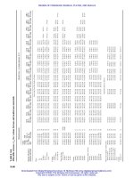
TABLE 25-49
Metal removal rate in milling operation, Q
Material Metal removal rate, Q,mm
3
/kW min
Cast iron, gray 12600
Cast steel 12600
Mild steel 18900
Alloy steel 10500
Stainless steel 8400
Aluminum 42000
Copper 18900
Titanium 10500
TABLE 25-50
Average unit power P
u
, for grinding
Unit power P
u
, kW/cm
3
/min
Depth of grinding, mm per pass
Work material Infeed, mm per revolution of work
0.0125 0.025 0.05 0.075 0.1 0.25 0.5 0.75
Free-machining steels 1.4 0.88 0.7 0.6 0.51 0.35 0.23 0.18
Mild steels
Medium carbon steels
Alloy steels 1.3 0.85 0.68 0.58 0.49 0.34 0.25 0.19
Tool steels 1.15 0.82 0.65 0.56 0.46 0.32 0.26 0.21
Stainless steels 1.4 0.84 0.65 0.58 0.51 0.37 0.29 0.26
Cast iron: gray, 1.15 0.79 0.65 0.51 0.44 0.3 0.23 0.19
ductile, malleable
Aluminum alloys 0.58 0.45 0.35 0.33 0.29 0.21 0.17 0.15
Titanium alloys 0.93 0.79 0.6 0.56 0.51 0.37 0.3 0.25
TABLE 25-51
Values of K
m
st,mm
2
0.3 0.4 0.6 0.8 1.0 1.2 1.4 1.6 1.8 2.0 2.4 2.6 2.8 3.0
K
m
Steel 32360 25500 21570 18140 15690 13720 12750 11750 10790 10300 9810 8830 8830 8330
N/m
2
Cast iron 29910 22550 17650 13730 11770 10780 9810 8825 8430 7845 7350 7355 7355 7110
25.68 CHAPTER TWENTY-FIVE
Downloaded from Digital Engineering Library @ McGraw-Hill (www.digitalengineeringlibrary.com)
Copyright © 2004 The McGraw-Hill Companies. All rights reserved.
Any use is subject to the Terms of Use as given at the website.
ELEMENTS OF MACHINE TOOL DESIGN
TABLE 25-52
Clearance between punch and die (Fig. 25-29)
Location of the proper clearance determines, either hole or blank size, punch size controls hole size, die size
controls blank size. 2C ¼ clearance ¼ d
p
À d
di
Clearance between punch and die, mm
Sheet thickness,
mm Mild steel Moderately hard steel Hard steel Soft brass Hard brass Aluminum
0.25 0.01 0.015 0.02 0.01 0.025 0.02
0.50 0.025 0.03 0.035 0,025 0.03 0.05
0.75 0.04 0.045 0.05 0.03 0.04 0.07
1.0 0.05 0.06 0.07 0.04 0.06 0.10
1.25 0.06 0.075 0.09 0.05 0.07 0.12
1.5 0.075 0.09 0.10 0.06 0.08 0.15
1.75 0.09 0.10 0.12 0,075 0.09 0.17
2.0 0.10 0.12 0.14 0.08 0.10 0.20
2.25 0.11 0.14 0.16 0.09 0.11 0.22
2.5 0.13 0.15 0.18 0.10 0.13 0.25
2.75 0.14 0.17 0.20 0.12 0.14 0.29
3.0 0.15 0.18 0.21 0.13 0.16 0.30
3.3 0.17 0.20 0.23 0.15 0.18 0.33
3.5 0.18 0.21 0.25 0.16 0.19 0.35
3.8 0.19 0.23 0.27 0.19 0.22 0.38
4.0 0.20 0.24 0.28 0.21 0.24 0.40
4.3 0.22 0.26 0.30 0.23 0.27 0.43
4.5 0.23 0.27 0.32 0.26 0.30 0.45
4.8 0.24 0.29 0.34 0.29 0.33 0.48
5.0 0.25 0.30 0.36 0.33 0.36 0.50
TABLE 25-53
Draw clearance, t ¼ thickness of the original blank
Blank thickness
mm in First draws Redraws Sizing draw
a
Up to 3.81 Up to 0.15 1.07t–1.09t 1.08t–1.1t 1.04t–1.05t
0.41–1.27 0.016–0.050 1.08t–1.1t 1.09t–1.12t 1.05t–1.06t
1.30–3.18 0.051–0.125 1.1t–1.12t 1.12t–1.14t 1.07t–1.09t
3.45 and up 0.136 and up 1.12t–1.14t 1.15t–1.2t 1.08t–1.1t
a
Used for straight-sided shells where diameter or wall thickness is important or where it is necessary to improve the surface finish in order to reduce
finishing costs.
ELEMENTS OF MACHINE TOOL DESIGN 25.69
Downloaded from Digital Engineering Library @ McGraw-Hill (www.digitalengineeringlibrary.com)
Copyright © 2004 The McGraw-Hill Companies. All rights reserved.
Any use is subject to the Terms of Use as given at the website.
ELEMENTS OF MACHINE TOOL DESIGN