Machine Design Databook Episode 1 part 5 pot
Bạn đang xem bản rút gọn của tài liệu. Xem và tải ngay bản đầy đủ của tài liệu tại đây (2.02 MB, 40 trang )
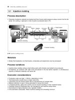
FIGURE 4-22 Reproduced with permission. Stress-concentration factor K
for notched flat bar in tension. (R. E. Peterson,
‘‘Design Factors for Stress Concentration,’’ Machine Design, Vol. 23, Nos. 2 to 7, 1951.)
(iii) Bar with shallow V-groove in tension for
r
h
1
> 1
(iv) Elliptical groove at the edge of plate in
tension
(v) Bar with symmetrical U, semicircular
shallow grooves in bending (Fig. 4-23).
K
v
¼ 1 þðK
v
À 1Þ 1 À
À
180 À
1 þ2:4
ffiffiffiffiffiffiffi
r=h
1
p
()
ð4-25Þ
K
¼ 1 þ
2h
1
b
ð4-26aÞ
K
¼ 1 þ2
ffiffiffiffiffi
h
1
r
r
ð4-26bÞ
K
¼ 1 þ
1
4:27
D
d
À 4
h
1
r
2
4
3
5
0:85
ð4-27aÞ
or
K
¼ 1 þ
D
d
À 1
2
4:27
D
d
À 4
d
r
2
6
6
6
4
3
7
7
7
5
0:85
ð4-27bÞ
Stress concentration factor theoretical/empirical
or otherwise
Particular Extreme value Formula
4.14 CHAPTER FOUR
Downloaded from Digital Engineering Library @ McGraw-Hill (www.digitalengineeringlibrary.com)
Copyright © 2004 The McGraw-Hill Companies. All rights reserved.
Any use is subject to the Terms of Use as given at the website.
STRESS CONCENTRATION AND STRESS INTENSITY IN MACHINE MEMBERS
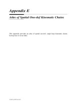
FIGURE 4-23 Reproduced with permission. Stress-con-
centration factor K
for notched flat bar in bending. (R. E.
Peterson, ‘‘Design Factors for Stress Concentration,’’
Machine Design, Vol. 23, Nos. 2 to 7, 1951.)
For stress-concentration factors for small grooves
in a shaft subjected to torsion.
(o) Bar containing shoulders
(i) Bar with shoulders in tension (Fig. 4-24)
TABLE 4-4
Stress-concentration factors for relatively small
grooves in a shaft subject to torsion, K
h
1
r
Included angle of V,deg0.51352
0 1.85 2.01 2.66 3.23 4.54
60 1.84 2.00 2.54 3.06 3.99
90 1.81 1.95 2.40 2.40 3.12
120 1.66 1.75 1.95 2.00 2.13
FIGURE 4-24 Reproduced with permission. Stress-con-
centration factor K
for filleted flat bar in tension. (R. E.
Peterson, ‘‘Design Factors for Stress Concentration,’’
Machine Design, Vol. 23, Nos. 2–7, 1951.)
Refer to Table 4-4.
K
¼ 1 þ
1
2:8
D
d
À 2
h
1
r
2
4
3
5
0:85
ð4-28aÞ
or
K
¼ 1 þ
D
d
À 1
2
2:8
D
d
À 2
d
r
2
6
6
6
4
3
7
7
7
5
0:85
ð4-28bÞ
Stress concentration factor theoretical/empirical
or otherwise
Particular Extreme value Formula
STRESS CONCENTRATION AND STRESS INTENSITY IN MACHINE MEMBERS
4.15
Downloaded from Digital Engineering Library @ McGraw-Hill (www.digitalengineeringlibrary.com)
Copyright © 2004 The McGraw-Hill Companies. All rights reserved.
Any use is subject to the Terms of Use as given at the website.
STRESS CONCENTRATION AND STRESS INTENSITY IN MACHINE MEMBERS
(ii) Bar with shoulders in bending (Fig. 4-25)
(p) Press-fitted or shrink-fitted members (Table 4-5):
(i) Plain member
(ii) Grooved member
(iii) Plain member
(iv) Grooved member
(q) Bolts and nuts (Tables 4-6 and 4-7)
Bolt and nut of standard proportions
Bolt and nut having lip
FIGURE 4-25 Reproduced with permission. Stress-concentration factor K
for stepped bar in bending. (R. E. Peterson,
‘‘Design Factors for Stress Concentration,’’ Machine Design, Vol. 23, Nos. 2 to 7, 1951.)
K
¼ 1 þ
1
5:37
D
d
À 4:8
h
1
r
2
4
3
5
0:85
ð4-29aÞ
or
K
¼ 1 þ
D
d
À 1
2
5:37
D
d
À 4:8
d
r
2
6
6
6
4
3
7
7
7
5
0:85
ð4-29bÞ
K
¼ 1:95
K
¼ 1:34
K
f
¼ 2:00
K
f
¼ 1:70
K
¼ 3:85
K
¼ 3:00
TABLE 4-5
Stress-concentration factors in shrink-fitted members
Particular K
K
f
Plain 1.95 2.00
Grooved 1.34 1.70
Stress concentration factor theoretical/empirical
or otherwise
Particular Extreme value Formula
4.16 CHAPTER FOUR
Downloaded from Digital Engineering Library @ McGraw-Hill (www.digitalengineeringlibrary.com)
Copyright © 2004 The McGraw-Hill Companies. All rights reserved.
Any use is subject to the Terms of Use as given at the website.
STRESS CONCENTRATION AND STRESS INTENSITY IN MACHINE MEMBERS
TABLE 4-6
Stress-concentration factors for screw threads
Analysis
Types of thread Seely and Smith Black (8) Peterson (1) Suggested value
Square 2.0
Sharp V 3.0
Whitworth 2.0 3.35 5 to 6
US standard
Medium
Carbon steel 2.5
National coarse thread
Heat-treated 2.84
Nickel steel 3.85
TABLE 4-7
Stress-concentration factors K
f
for screw threads
Annealed Hardened
Type of thread Rolled Cut Rolled Cut
Sellers, American
National, square thread
2.2 2.8 3.0 3.8
Whitworth rounded roots 1.4 1.8 2.6 3.3
TABLE 4-8
Stress-concentration factors for welds
Location K
End or parallel fillet weld 2.7
Reinforced butt 1.2
Tee of transverse fillet weld 1.5
T-butt weld with sharp corners 2.0
TABLE 4-9
Index of sensitivity for repeated stress
Average index of sensitivity q
Material Annealed or soft
Heat-treated and drawn
at 921 K (6488C)
Heat-treated and drawn
at 755 K (4828C)
Armco iron, 0.02% C 0.15–0.20
Carbon steel
0.10% C 0.05–0.10
0.20% C (also cast steel) 0.10
0.30% C 0.18 0.35 0.45
0.50% C 0.26 0.40 0.50
0.85% C 0.45 0.57
Spring steel, 0.56% C, 2.3 Si, rolled 0.38
SAE 3140, 0.73 C; 0.6 Cr; 1.3 Ni. 0.25 0.45
Cr–Ni steel 0.8 Cr; 3.5 Ni 0.25 0.70
Stainless steel, 0.3 C; 8.3 Cr, 19.7 Ni 0.16
Cast iron 0–0.05
Copper, electrolitic 0.07
Duraluminum 0.05–0.13
STRESS CONCENTRATION AND STRESS INTENSITY IN MACHINE MEMBERS
4.17
Downloaded from Digital Engineering Library @ McGraw-Hill (www.digitalengineeringlibrary.com)
Copyright © 2004 The McGraw-Hill Companies. All rights reserved.
Any use is subject to the Terms of Use as given at the website.
STRESS CONCENTRATION AND STRESS INTENSITY IN MACHINE MEMBERS
(r) Crane hook:
For crane hook under tensile load
(s) Rotating disk:
For rotating disk with a hole for
R
i
R
o
! 0
For thin disk (ring)
(t) Eye bar:
For eye bar subjected to tensile load
Stress concentration factors for welds
(u) Notch sensitivity factors (Table 4 -9):
(i) Notch sensitivity factor for normal stress
For index of sensitivity for repeated stresses.
(ii) Fatigue stress concentration factor for
normal stress
(iii) Notch sensitivity factor for shear stress
(iv) Fatigue stress-concentration factor for shear
stress
STRESS CONCENTRATION IN FLANGED PIPE
SUBJECTED TO AXIAL EXTERNAL FORCE
The stress in the pipe due to external load F (Fig.
4-25A)
FIGURE 4-25A Pipe and flange under the axial force F
K
¼ 1:56
K
¼ 2
K
¼ 1
K
¼ 2:8
Refer to Table 4-8.
q
¼
K
f
À 1
K
À 1
ð4-30aÞ
q
¼
K
f
À 1
K
0
À 1
ð4-30bÞ
Refer to Table 4-9.
K
f
¼ 1 þq
ðK
À 1Þð4-31aÞ
K
f
¼ 1 þq
ðK
0
À 1Þð4-31bÞ
q
¼
K
f
À 1
K
À 1
ð4-32Þ
K
f
¼ 1 þq
ðK
À 1Þð4-33Þ
¼
f
þ
F
A
ð4-33aÞ
where
f
¼ depends on the distance x from the
flange of the pipe, MPa (psi)
fm
¼ maximum stress at x ¼ 0, MPa (psi)
A ¼ area of the cross section of pipe, m
2
(in
2
)
F ¼ external load, kN (lbf)
Stress concentration factor theoretical/empirical
or otherwise
Particular Extreme value Formula
4.18 CHAPTER FOUR
Downloaded from Digital Engineering Library @ McGraw-Hill (www.digitalengineeringlibrary.com)
Copyright © 2004 The McGraw-Hill Companies. All rights reserved.
Any use is subject to the Terms of Use as given at the website.
STRESS CONCENTRATION AND STRESS INTENSITY IN MACHINE MEMBERS
The value of constant
For plot of the stress ratio
f
fm
versus x
FIGURE 4-25B Stress concentration region in flanged pipe under axial external force F.
Courtesy: Douglas C. Greenwood, Engineering Data for Product Design, McGraw-Hill Publishing Company, New York, 1961.
¼ 10
4
ffiffiffiffiffiffiffiffiffiffiffiffiffiffiffiffiffiffiffi
3ð1 À
2
Þ
R
2
h
2
s
ð4-33bÞ
where 2R ¼ 2R
i
þ h ¼
mean diameter of pipe, m (in)
2R
o
¼ outer diameter of pipe, m (in)
2R
i
¼ inner diameter of pipe, m (in)
h ¼ thickness of pipe, m (in)
¼ Poisson’s ratio of material
Refer to Fig. 4-25B.
Particular Formula
REDUCTION OR MITIGATION OF STRESS CONCENTRATIONS
In designing a machine part, one has to take into consideration the stress concentration occurring in such parts and
eliminate or reduce stress concentration. Fig. 4-25C shows various methods used to reduce stress concentration.
Stream line flowing analogy in a channel can be applied to force flow lines of a flat plate without any type of flow
subject to uniform uniaxial tensile stress as shown in Fig. 4-25C i(a). The stream line flow of water or any fluid is
STRESS CONCENTRATION AND STRESS INTENSITY IN MACHINE MEMBERS 4.19
Downloaded from Digital Engineering Library @ McGraw-Hill (www.digitalengineeringlibrary.com)
Copyright © 2004 The McGraw-Hill Companies. All rights reserved.
Any use is subject to the Terms of Use as given at the website.
STRESS CONCENTRATION AND STRESS INTENSITY IN MACHINE MEMBERS
smooth and straight as shown in Fig. 4-25C i(a). If there is any obstruction such as a heavy iron ball or a pipe or
stone boulder in the path of flow of water, the flow of water or fluid will not be smooth and straight as shown in
Fig. 4-25C i(e). Similarly the force flow lines will not be straight as in case of plate with a circular or elliptical or any
shape of holes in a plate as shown in Figs. 4-25C i(b), i(c), i(d) and i( f ). By providing some geometric changes,
abrupt change of force-flow lines are smoothened. Fatigue strength of parts with stress raiser can be increased
by cold working operation such as shot peening or pressing by balls which creates a nature of stress in thin
layers of the part just opposite to the one induced in it. Press fit stress concentration can be reduced by making
the gripping portion conical in case of hardening steel parts. Nitriding and plating the parts eliminate the corrosion
effect, which combined with stress concentration reduces the fatigue strength of the machine part.
(i) Plates:
4.20 CHAPTER FOUR
Downloaded from Digital Engineering Library @ McGraw-Hill (www.digitalengineeringlibrary.com)
Copyright © 2004 The McGraw-Hill Companies. All rights reserved.
Any use is subject to the Terms of Use as given at the website.
STRESS CONCENTRATION AND STRESS INTENSITY IN MACHINE MEMBERS
(ii) Stepped shafts subject to tensile force:
STRESS CONCENTRATION AND STRESS INTENSITY IN MACHINE MEMBERS 4.21
Downloaded from Digital Engineering Library @ McGraw-Hill (www.digitalengineeringlibrary.com)
Copyright © 2004 The McGraw-Hill Companies. All rights reserved.
Any use is subject to the Terms of Use as given at the website.
STRESS CONCENTRATION AND STRESS INTENSITY IN MACHINE MEMBERS
(iii) Shafts with narrow collar, cylindrical holes and grooves subject to tensile force:
(iv) Shafts subject to bending and torque:
4.22 CHAPTER FOUR
Downloaded from Digital Engineering Library @ McGraw-Hill (www.digitalengineeringlibrary.com)
Copyright © 2004 The McGraw-Hill Companies. All rights reserved.
Any use is subject to the Terms of Use as given at the website.
STRESS CONCENTRATION AND STRESS INTENSITY IN MACHINE MEMBERS
(v) Screws and nuts under torque:
(vi) Keyways in shafts subject to torque:
STRESS CONCENTRATION AND STRESS INTENSITY IN MACHINE MEMBERS 4.23
Downloaded from Digital Engineering Library @ McGraw-Hill (www.digitalengineeringlibrary.com)
Copyright © 2004 The McGraw-Hill Companies. All rights reserved.
Any use is subject to the Terms of Use as given at the website.
STRESS CONCENTRATION AND STRESS INTENSITY IN MACHINE MEMBERS
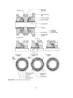
(vii) Gears:
Stress concentration at fillet and at point of contact are shown in photoelastic fringe pattern and also in Fig. c.The
stress concentration at fillet can be reduced by providing suitable large fillet radius.
Source: From the photoelastic work of K. Lingaiah, Fringe Pattern of Gear-Teeth Showing Stress Concentration at
Root and Contact Point, Department of Mechanical Engineering, University Visvesvaraya College of Engineering,
Bangalore University, Bangalore, 1973.
(viii) Flate plate with and without asymmetrically reinforced circular cutout subjected to uniform uniaxial stress:
FIGURE 4-25C Mitigation of stress concentration in machine members.
s
h
(
a
)
Forces acting on a Gear Tooth Profile
due to Normal Force F
n
b
F
θ
F
n
F
r
ρ
t
Maximum Fringe order
(c)
Maximum Fringe
order means
maximum stress at
point of contact
Tension side of root
fillet with less stress
concentration
Compression side of root fillet gear
tooth with more fringes compare to
tension side root fillet stress analysis
of gear teeth in contact under load
showing photoelastic fringes by using
the results of photoelastic experiment
ρ
t
β
α
α
Fringe pattern of gear teeth
in contact showing stress
concentration at root and point
of contract
(b)
4.24 CHAPTER FOUR
Downloaded from Digital Engineering Library @ McGraw-Hill (www.digitalengineeringlibrary.com)
Copyright © 2004 The McGraw-Hill Companies. All rights reserved.
Any use is subject to the Terms of Use as given at the website.
STRESS CONCENTRATION AND STRESS INTENSITY IN MACHINE MEMBERS
STRESS INTENSITY FACTOR OR
FRACTURE TOUGHNESS FACTOR
The energy criterion approach in the fracture
mechanics analysis:
The energy release rate in case of a crack of length 2a
in an infinite plate subject to tensile stress at infinity
(Fig. 4-26A).
The energy release rate is defined as the rate of change
in potential energy with crack area for a linear elastic
material.
The critical energy release rate.
FIGURE 4-26A A flat infinite plate with a through thickness crack subject to tensile stress at infinity.
The stress intensity factor for a centrally located
straight crack in an infinite plate subjected to uniform
uniaxial tensile stress perpendicular to the plane of
the crack.
The definition and unit of critical stress intensity
factor K
Ic
.
The relation between K
I
and G.
G ¼
2
a
E
ð4-34aÞ
where G ¼ energy release rate
E ¼ modulus of elasticity, GPa (psi)
a ¼ half crack length, mm (in)
G
c
¼
2
f
a
c
E
ð4-34bÞ
where
f
¼ failure stress, MPa (psi)
G
c
¼ material resistance to fracture or
critical fracture toughness
K
I
¼
ffiffiffi
p
ffiffiffi
a
p
ð4-34cÞ
K
Ic
is the critical stress intensity factor for static
loading and plane-strain conditions of maximum con-
straints and is also referred to as the fracture tough-
ness factor of the material at the onset of rapid
fracture and has dimension of (stress
ffiffiffiffiffiffiffiffiffiffiffiffiffi
length
p
), i.e.
MPa
ffiffiffiffi
m
p
(kpsi
ffiffiffiffi
in
p
).
G ¼
K
I
E
ð4-34dÞ
Particular Formula
STRESS CONCENTRATION AND STRESS INTENSITY IN MACHINE MEMBERS
4.25
Downloaded from Digital Engineering Library @ McGraw-Hill (www.digitalengineeringlibrary.com)
Copyright © 2004 The McGraw-Hill Companies. All rights reserved.
Any use is subject to the Terms of Use as given at the website.
STRESS CONCENTRATION AND STRESS INTENSITY IN MACHINE MEMBERS
Three modes of loading to analyse stress
fields in cracks:
FIGURE 4-26B Three modes of loading for deformation of crack tip.
First mode of loading and stress components
at crack tip, Fig. 4-26B (a):
The localized stress components at the vicinity of the
‘‘opening mode’’ or ‘‘mode I’’ crack tip in a flat plate
subjected to uniform applied stress at infinity from
the theory of fracture mechanics (Fig. 4-26C).
The crack tip displacement fields for ‘‘first mode’’
(Mode I) in case of linear elastic, isotropic materials.
FIGURE 4-26C State of stress in the vicinity of a crack tip.
x
¼
K
I
ffiffiffiffiffiffiffi
2r
p
cos
2
1 À sin
2
sin
3
2
ð4-35aÞ
y
¼
K
I
ffiffiffiffiffiffiffi
2r
p
cos
2
1 þ sin
2
sin
3
2
ð4-35bÞ
z
¼ ð
x
þ
y
Þ for plane strain ð4-35cÞ
¼ 0 for plane stress ð4-35dÞ
xy
¼
K
I
ffiffiffiffiffiffiffi
2r
p
cos
2
sin
2
cos
3
2
ð4-35eÞ
u
x
¼
K
I
2G
ffiffiffiffiffiffi
r
2
r
cos
2
À 1 þ2 sin
2
2
ð4-35f Þ
u
y
¼
K
I
2G
ffiffiffiffiffiffi
r
2
r
sin
2
þ 1 À2 cos
2
2
ð4-35gÞ
where G ¼ modulus of shear, GPa (psi)
¼ 3 À4 for plane strain
¼ð3 ÀÞ=ð1 þÞ for plane stress
Particular Formula
4.26 CHAPTER FOUR
Downloaded from Digital Engineering Library @ McGraw-Hill (www.digitalengineeringlibrary.com)
Copyright © 2004 The McGraw-Hill Companies. All rights reserved.
Any use is subject to the Terms of Use as given at the website.
STRESS CONCENTRATION AND STRESS INTENSITY IN MACHINE MEMBERS
Second mode of loading and stress
components in the vicinity of crack tip,
Fig. 4-26B (b):
The localized stress components at the vicinity of the
‘‘second mode’’ or ‘‘sliding mode’’ crack tip in a flat
plate subjected to in-plane shear, Fig. 4-26B (b).
The crack tip displacement fields for the ‘‘second
mode’’ (Mode II) in case of linear elastic, isotropic
materials.
Third mode of loading and stress components
in the vicinity of crack tip, Fig. 4-26B (c):
The localized stress components at the vicinity of the
‘‘third mode’’ or ‘‘tearing mode III’’ crack tip in a flat
plate subjected to out-of-plane shear, Fig. 4-26B (c),
in case of linear elastic, isotropic materials.
The crack tip displacement field for the ‘‘third mode’’
(Mode III) in case of linear elastic, isotropic materials.
Stress intensity factor:
The stress intensity factor for a center cracked tension
plate (CCT), according to Fedderson (Fig. 4-27a).
The stress intensity factor for a double edge cracked
plate according to Keer and Freedman (Fig. 4-27b).
x
¼À
K
II
ffiffiffiffiffiffiffi
2r
p
sin
2
2 þ cos
2
cos
3
2
ð4-35hÞ
y
¼
K
II
ffiffiffiffiffiffiffi
2r
p
sin
2
cos
2
cos
3
2
ð4-35iÞ
xy
¼
K
II
ffiffiffiffiffiffiffi
2r
p
cos
2
1 À sin
2
sin
3
2
ð4-35jÞ
z
¼ 0 for plane stress ð4-35kÞ
z
¼ ð
x
À
y
Þ for plane strain ð4-35lÞ
xz
¼
yz
¼ 0 ð4-35mÞ
u
x
¼
K
II
2G
ffiffiffiffiffiffi
r
2
r
sin
2
þ 1 þ2 cos
2
2
ð4-35nÞ
u
y
¼À
K
II
2G
ffiffiffiffiffiffi
r
2
r
cos
2
À 1 À2 sin
2
2
ð4-35oÞ
xz
¼
K
III
ffiffiffiffiffiffiffi
2r
p
sin
2
ð4-35pÞ
yz
¼
K
III
ffiffiffiffiffiffiffi
2r
p
cos
2
ð4-35qÞ
u
z
¼
K
III
G
ffiffiffiffiffiffi
r
2
r
sin
2
ð4-35rÞ
w ¼ ¼ 0
K
I
¼
ffiffiffiffiffiffi
a
p
sec
a
2b
ð4-35sÞ
K
i
¼
ffiffiffiffiffiffi
a
p
1:12 À 0:61
a
b
þ 0:13
a
b
3
Â
1 À
a
b
À1=2
ð4-35tÞ
Particular Formula
STRESS CONCENTRATION AND STRESS INTENSITY IN MACHINE MEMBERS
4.27
Downloaded from Digital Engineering Library @ McGraw-Hill (www.digitalengineeringlibrary.com)
Copyright © 2004 The McGraw-Hill Companies. All rights reserved.
Any use is subject to the Terms of Use as given at the website.
STRESS CONCENTRATION AND STRESS INTENSITY IN MACHINE MEMBERS
The stress intensity factor for the plate with a single
edge crack, according to Gross, Srawley and Brown
(Fig. 4-27c).
The stress intensity factor for single edged cracked
plate/specimen subjected to bending (M
b
) (Fig.
4-27d).
Stress intensity factor for the case of angled
crack (Fig. 4-27A):
FIGURE 4-27A Through crack in an infinite plate for the
general case where the crack plane is inclined at 908 À
angle from the applied normal stress acting at infinity.
The stress intensity factors for Modes I and II.
K
I
¼
ffiffiffiffiffiffi
a
p
1:12 À 0:23
a
b
þ 10:6
a
b
2
À 21:7
a
b
3
þ 30:4
a
b
4
ð4-35uÞ
K
I
¼
ffiffiffiffiffiffi
a
p
1:112 À 1:40
a
b
þ 7:33
a
b
2
À 13:08
a
b
3
þ 14:0
a
b
4
ð4-35vÞ
K
I
¼ K
Ið0Þ
cos
2
ð4-36aÞ
K
II
¼ K
Ið0Þ
cos sin ð4-36bÞ
where K
Ið0Þ
is the Mode I stress intensity factor when
¼ 0
FIGURE 4-27a
FIGURE 4-27b
FIGURE 4-27c
FIGURE 4-27d
Particular Formula
4.28 CHAPTER FOUR
Downloaded from Digital Engineering Library @ McGraw-Hill (www.digitalengineeringlibrary.com)
Copyright © 2004 The McGraw-Hill Companies. All rights reserved.
Any use is subject to the Terms of Use as given at the website.
STRESS CONCENTRATION AND STRESS INTENSITY IN MACHINE MEMBERS
Equations for stress and displacement
components in terms of polar coordinates:
The localized stress components at the vicinity of
Mode I crack tips in terms of polar coordinates.
The crack tip displacement fields for ‘‘first mode’’
(Mode I) in case of linear elastic, isotropic materials.
The localized stress components at the vicinity of
Mode II crack tip in terms of polar coordinates.
The crack tip displacement fields for Mode II.
r
¼
K
I
4
ffiffiffiffiffiffiffi
2r
p
5 cos
2
À cos
3
2
ð4-36cÞ
¼
K
I
4
ffiffiffiffiffiffiffi
2r
p
3 cos
2
þ cos
3
2
ð4-36dÞ
r
¼
K
I
4
ffiffiffiffiffiffiffi
2r
p
sin
2
þ sin
3
2
ð4-36eÞ
z
¼
1
ð
r
þ
Þð4-36f Þ
where
1
¼ 0 for plane stress and
1
is Poisson’s ratio,
, for plane strain. These singular fields only apply as
r ! 0.
u
r
¼
K
I
2E
ffiffiffiffiffiffi
r
2
r
ð1 þ Þ
ð2 À 1Þcos
2
À cos
3
2
ð4-36gÞ
u
¼
K
I
2E
ffiffiffiffiffiffi
r
2
r
ð1 þ Þ
Àð2 À 1Þsin
2
þ sin
3
2
ð4-36hÞ
u
z
¼À
2
z
E
ð
r
þ
0
Þð4-36iÞ
where
¼
3 À
1 þ
,
1
¼ 0, and
2
¼ for plane stress
¼ð3 À 4Þ,
1
¼ , and
2
¼ 0 for plain strain
K
I
is given by Eq. (4-36a).
r
¼
K
II
ffiffiffiffiffiffiffi
2r
p
sin
2
1 À 3 sin
2
2
ð4-36jÞ
¼
3K
II
ffiffiffiffiffiffiffi
2r
p
sin
2
cos
2
2
ð4-36kÞ
u
r
¼
K
II
2E
ffiffiffiffiffiffi
r
2
r
ð1 þ Þ
Àð2 À 1Þsin
2
þ 3 sin
3
2
ð4-36lÞ
u
¼
K
II
2E
ffiffiffiffiffiffi
r
2
r
ð1 þ Þ
Àð2 À 1Þcos
2
þ 3 cos
3
2
ð4-36mÞ
Particular Formula
STRESS CONCENTRATION AND STRESS INTENSITY IN MACHINE MEMBERS
4.29
Downloaded from Digital Engineering Library @ McGraw-Hill (www.digitalengineeringlibrary.com)
Copyright © 2004 The McGraw-Hill Companies. All rights reserved.
Any use is subject to the Terms of Use as given at the website.
STRESS CONCENTRATION AND STRESS INTENSITY IN MACHINE MEMBERS
The localized stress components and crack tip dis-
placement fields for Mode III in terms of polar
coordinates.
The critical applied tensile stress necessary for crack
extension according to Griffith theory for brittle
metals.
The modified Griffith’s equation for a small amount
of plastic deformation according to Orowan which
can be applied to ductile materials at low tem-
perature, high strain rate and localized geometric
constraint.
The elastic energy release rate for Mode I.
The elastic energy release rate for Mode II.
The elastic energy release rate for Mode III.
The stress-intensity factor for a centrally located
straight crack in an infinite plate subjected to uniform
shear stress .
The stress-intensity magnification factor for a cen-
trally located straight crack of length 2a in a flat
plate whose length 2h and width 2b are very large
compared with the crack length subjected to uniform
uniaxial tensile stress .
For stress-intensity magnification factors of plates
with straight crack located at various positions in
the plate and cylinders subjected to various types of
rate of loadings and for various values of a=b, a=d,
a=h, a=ðr
o
À r
i
Þ, and other ratios.
The factor of safety.
r
¼
K
III
ffiffiffiffiffiffiffi
2r
p
sin
2
ð4-36nÞ
¼
K
III
ffiffiffiffiffiffiffi
2r
p
cos
2
ð4-36pÞ
u
z
¼
2K
III
G
ffiffiffiffiffiffi
r
2
r
sin
2
ð4-36qÞ
c
/
ffiffiffiffiffiffiffiffi
EU
a
r
ð4-36rÞ
where
c
¼ critical applied stress
E ¼ Young’s modulus
U ¼ surface energy per unit area
a ¼ crack length.
¼
ffiffiffiffiffiffiffiffiffiffiffiffiffiffiffiffiffiffiffiffi
EðU þ pÞ
a
r
ð4-36sÞ
where p ¼ plastic deformation energy per unit area
for metallic solid, p ) U.
G
I
¼
1 À
2
E
K
2
I
for plane strain ð4-36tÞ
¼ K
2
I
=E for plane stress ð4-36uÞ
G
II
¼
ð1 À
2
Þ
E
K
2
II
ð4-36vÞ
G
III
¼
ð1 þ Þ
E
K
2
III
ð4-36wÞ
K
I
À iK
II
¼Ài
ffiffiffi
p
ffiffiffi
a
p
ð4-37aÞ
MF ¼
K
I
ffiffiffi
p
ffiffiffi
a
p
ð4-37bÞ
Refer to Figs. from 4-28, 4-29 to 4-34.
n ¼
K
Ic
K
ð4-38Þ
Particular Formula
4.30 CHAPTER FOUR
Downloaded from Digital Engineering Library @ McGraw-Hill (www.digitalengineeringlibrary.com)
Copyright © 2004 The McGraw-Hill Companies. All rights reserved.
Any use is subject to the Terms of Use as given at the website.
STRESS CONCENTRATION AND STRESS INTENSITY IN MACHINE MEMBERS
FIGURE 4-28 Stress intensity magnification factor
K
I
=
ffiffiffi
p
ffiffiffi
a
p
for various ratios a=b of a flat plate with a cen-
trally located straight crack under the action of uniform uni-
axial tensile stress .
FIGURE 4-30 Stress intensity magnification factor
K
I
=
ffiffiffi
p
ffiffiffi
a
p
for an edge straight crack in a flat plate subjected
to uniform uniaxial tensile stress for solid curves there are
no constraints to bending; the dashed curve was obtained
with bending constraints added.
FIGURE 4-29 Stress intensity magnification factor
K
I
=
ffiffiffi
p
ffiffiffi
a
p
for an off-center straight crack in a flat plate sub-
jected to uniform unidirectional tensile stress ; solid curves
are for the crack tip at A; dashed curves for tip at B.
FIGURE 4-31 Stress intensity magnification factor
K
I
=
ffiffiffi
p
ffiffiffi
a
p
for a rectangular cross-sectional beam subjected
to bending M
b
.
STRESS CONCENTRATION AND STRESS INTENSITY IN MACHINE MEMBERS
4.31
Downloaded from Digital Engineering Library @ McGraw-Hill (www.digitalengineeringlibrary.com)
Copyright © 2004 The McGraw-Hill Companies. All rights reserved.
Any use is subject to the Terms of Use as given at the website.
STRESS CONCENTRATION AND STRESS INTENSITY IN MACHINE MEMBERS
FIGURE 4-32 Stress intensity magnification factor
K
I
=
ffiffiffi
p
ffiffiffi
a
p
for a flat plate with a centrally located circular
hole with two straight cracks under uniform uniaxial tensile
stress .
FIGURE 4-33 Stress intensity magnification factor
K
I
=
ffiffiffi
p
ffiffiffi
a
p
for axially tensile loaded cylinder with a radial
crack of a depth extending completely around the circumfer-
ence of the cylinder.
FIGURE 4-34 Stress intensity magnification factor K
I
=
ffiffiffi
p
ffiffiffi
a
p
for a cylinder subjected to internal pressure p
i
having a radial
crack in the longitudinal direction of depth a. Use equation of tangential stress of thick cylinder subjected to internal pressure to
calculate the stress
at r ¼ r
o
.
4.32 CHAPTER FOUR
Downloaded from Digital Engineering Library @ McGraw-Hill (www.digitalengineeringlibrary.com)
Copyright © 2004 The McGraw-Hill Companies. All rights reserved.
Any use is subject to the Terms of Use as given at the website.
STRESS CONCENTRATION AND STRESS INTENSITY IN MACHINE MEMBERS
Critical crack length
For values of critical stress-intensity factor (K
Ic
) for
some engineering materials.
REFERENCES
1. Lingaiah, K., Solution of an Asymmetrically Reinforced Circular Cut-out in a Flat Plate Subjected to
Uniform Unidirectional Stress, Ph.D. Thesis, Department of Mechanical Engineering, University of
Saskatchewan, Saskatoon, Sask., Canada, 1965.
2. Lingaiah, K., W. P. T. North, and J. B. Mantle, ‘‘Photoelastic Analysis of an Asymmetrically Reinforced
Circular Cut-out in a Flat Plate Subjected to Uniform Unidirectional Stress,’’ Proc. SESA, Vol. 23, No. 2
(1966), p. 617.
3. Peterson, R. E., ‘‘Design Factors for Stress Concentration,’’ Machine Design, Vol. 23, No. 27, Pentagon Pub-
lishing, Cleveland, Ohio, 1951.
4. Lingaiah, K., ‘‘Effect of Contact Stress on Fatigue Strength of Gears,’’ M.Tech. Thesis, Indian Institute of
Technology, Kharagpur, India, 1958.
5. Lingaiah, K., ‘‘Photoelastic Stress Analysis of Gear Teeth Under Load,’’ Department of Mechanical
Engineering, University Visveswaraya College of Engineering, Bangalore University, Bangalore, 1980.
6. Lingaiah, K., and B. R. Narayana Iyengar, Machine Design Data Handbook, Vol. I (SI and Customary Metric
Units), Suma Publishers, Bangalore, India, 1986.
7. Lingaiah, K., Machine Design Data Handbook, Vol. II (SI and Customary Metric Units), Suma Publishers,
Bangalore, India, 1986.
a
c
¼
1
K
Ic
sy
=2
2
Refer to Table 4-10.
Particular Formula
TABLE 4-10
Plane-strain fracture toughness or stress intensity factor K
Ic
for some engineering materials
Material K
Ic
Yield strength,
xy
Critical crack length, a
c
Previous designation UNS designation MPa
ffiffiffiffi
m
p
kpsi
ffiffiffiffi
in
p
MPa kpsi mm in
Aluminum
2014-T651 24.2 22 455 66 3.6 0.14
2024-T851 A92024-T851 26 24 455 66 4.3 0.17
7075-T651 A97075-T651 24 22 495 72 3.0 0.12
7178 13 30 490 71 5.8 0.23
Titanium
Ti-6Al-4V R56401 115 105 910 132 20.5 0.81
Ti-6Al-4V
Ã
R56401
Ã
55 50 1035 150 3.6 0.14
Steel
4340 G43400 99 90 860 125 16.8 0.66
4340
Ã
G43400
Ã
60 55 1515 220 2 0.08
H-11 – 38.5 35 1790 260 <0.6 <0.02
H-11 – 27.8 27 2070 300 0.23 0.009
52100 G52986 14 13 2070 300 <0.06 <0.002
Ã
Heat treated to a higher strength.
STRESS CONCENTRATION AND STRESS INTENSITY IN MACHINE MEMBERS 4.33
Downloaded from Digital Engineering Library @ McGraw-Hill (www.digitalengineeringlibrary.com)
Copyright © 2004 The McGraw-Hill Companies. All rights reserved.
Any use is subject to the Terms of Use as given at the website.
STRESS CONCENTRATION AND STRESS INTENSITY IN MACHINE MEMBERS
8. Lingaiah, K., Machine Design Data Handbook (SI and Customary US Units), McGraw-Hill Publishing Com-
pany, New York, 1994.
9. Aidad, T., and Y. Terauchi, ‘‘On the Bending Stress in a Spur Gear,’’ 3 Reports, Bull. JSME, Vol. 5 (1962),
p. 161.
10. Dolan, T. J., and E. L. Broghamer, ‘‘A Photoelastic Study of Stresses in Gear Tooth Fillets,’’ Univ. Illinois
Exptl. Station. Bull., 335 (1942).
11. Hetenyi, M., The Application of Hardening Resins in Three-Dimensional Photoelastic Studies, J. Appl. Phys.,
Vol. 10 (1939), p. 295.
12. Shigley, J. E., and L. D. Mitchell, Mechanical Engineering Design, McGraw-Hill Publishing Company, New
York, 1983.
13. Greenhood, D. C., Engineering Data for Production Design, McGraw-Hill Publishing Company, New York,
1961.
14. Carlson, R. L., and G. A. Kardomateas, An Introduction to Fatigue in Metals and Composites.
15. Anderson, T. L., Fracture Mechanics—Fundamentals and Application, 2nd edition, CRC Press, New York,
1995.
16. Fedderson, C., ‘‘Discussion’’, in Plane Strain Crank Toughness Testing of High Strength Metallic Materials,
ASTM STP410, American Society for Testing Materials, Philadelphia (1967), p. 77.
17. Keer, L. M., and J. M. Freedman, ‘‘Tensile Strip with Edge Cracks,’’ Int. J. Engineering Science, Vol. 11
(1973), pp. 1965–1075.
18. Gross, B., and J. E. Srawley, ‘‘Stress Intensity Factors for Bend and Compact Specimens,’’ Engineering
Fracture Mechanics, Vol. 4 (1972), pp. 587–589.
19. Gross, B., J. E. Srawley, and W. E. Brown Jr., Stress Intensity Factors for a Single Edge Notch Tension
Specimen by a Boundary Collocation of a Stress Function, NASA Technical Note D-2395, 1964.
20. Damage Tolerant Design Handbook, MICIC-HB-01, Air Force Materials Laboratory, Wright-Patterson Air
Force Base, Ohio, December 1972, and supplements.
4.34 CHAPTER FOUR
Downloaded from Digital Engineering Library @ McGraw-Hill (www.digitalengineeringlibrary.com)
Copyright © 2004 The McGraw-Hill Companies. All rights reserved.
Any use is subject to the Terms of Use as given at the website.
STRESS CONCENTRATION AND STRESS INTENSITY IN MACHINE MEMBERS
CHAPTER
5
DESIGN OF MACHINE ELEMENTS
FOR STRENGTH
SYMBOLS
5;6
A area of cross-section, m
2
(in
2
)
b a shape factor (b > 0)
B a constant
e
sz
size coefficient
e
s
surface coefficient in case of tension and bending
e
0
s
surface coefficient in case of torsion
E Young’s modulus, GPa (Mpsi)
F normal load (also with suffixes and primes), kN (lbf)
F
0
m
static equivalent of cyclic load, kN (lbf)
G modulus of rigidity, GPa (Mpsi)
h thickness, m (in)
K
sz
size factor
K
s
surface factor
K
theoretical normal stress-concentration factor
K
theoretical shear stress-concentration factor
K
f
fatigue normal stress-concentration factor
K
f
fatigue shear stress-concentration factor
M
b
bending moment (also with suffixes and primes), N m (lbf in)
M
0
bm
static equivalent of cyclic bending moment, N m (lbf in)
M
t
twisting moment (also with suffixes and primes), N m (lbf in)
M
0
tm
static equivalent of cyclic twisting moment, N m (lbf in)
n safety factor
a constant
n
a
actual safety factor (also with suffixes)
n
d
design safety factor (also with suffixes)
q index of sensitivity
q
f
index of notch sensitivity for alternating stresses
r notch radius, mm (in)
t time, h
x
0
the guaranteed value of x (x
0
! 0)
y
max
maximum deflection
Z
b
flexural section modulus, m
3
or cm
3
(in
3
)
Z
t
polar section modulus, m
3
or cm
3
(in
3
)
characteristic or scale value ( ! x
0
)
5.1
Downloaded from Digital Engineering Library @ McGraw-Hill (www.digitalengineeringlibrary.com)
Copyright © 2004 The McGraw-Hill Companies. All rights reserved.
Any use is subject to the Terms of Use as given at the website.
Source: MACHINE DESIGN DATABOOK
normal stress (also with suffixes and primes), MPa (psi)
0
initial stress, MPa (psi)
su
ultimate strength, MPa (psi)
e
elastic limit for standard specimen for 12.5 mm (
1
2
in), MPa (psi)
d
design stress (also with suffixes), MPa (psi)
x
normal stress in x direction, MPa (psi)
y
yield stress, MPa (psi)
normal stress in y direction, MPa (psi)
nom
nominal normal stress, MPa (psi)
max
maximum normal stress, MPa (psi)
0
e
elastic limit for any thickness h between 12.5 mm (
1
2
in) and
75 mm (3 in), MPa (psi)
00
e
elastic limit for 75 mm (3 in) specimen, MPa (psi)
fb
endurance limit in bending, MPa (psi)
shear stress (also with suffixes and primes), MPa (psi)
e
elastic limit in shear, MPa (psi)
sy
yield strength in shear, MPa (psi)
xy
shear stress in xy plane, MPa (psi)
nom
nominal shear stress, MPa (psi)
f
endurance limit in torsion, MPa (psi)
" engineering or average strain, mm/m (min/in)
"
0
true strain, mm/m (min/in)
"
t
total creep, after a time t, mm/m (min/in)
"
0
initial creep, mm/m (min/in)
_
"" creep rate (m/m)/h [(min/in)/h]
v
0
a constant
Suffixes for
s static strength (
u
or
y
)
u ultimate strength
y yield strength
e elastic limit
a amplitude
b bending
m mean
t tension
max maximum
min minimum
f endurance limit (also used for reversed cycle)
o endurance limit repeated cycle
Primes for
0
(single) static equivalent
00
(double) combined stress
5.2 CHAPTER FIVE
Downloaded from Digital Engineering Library @ McGraw-Hill (www.digitalengineeringlibrary.com)
Copyright © 2004 The McGraw-Hill Companies. All rights reserved.
Any use is subject to the Terms of Use as given at the website.
DESIGN OF MACHINE ELEMENTS FOR STRENGTH
STATIC LOADS
Influence of size
The size coefficient (Fig. 5-1, Fig. 5-2, and Table 5-1)
e
sz
¼ 1 À0:016
1 À
00
e
e
ðh À 12:5Þð5-1Þ
where
e
¼ elastic limit for 12.5 mm (0.5 in)
00
e
¼ elastic limit for 75 mm (3.0 in)
Particular Formula
TABLE 5-1
Strength ratios of various materials for use in Eqs. (5-1) and (5-2)
Values of
00
e
=
e
Material Natural state Annealed
Drawn at
6508C
Drawn at
5358C
Drawn at
4258C
Aluminum, strong, wrought 0.93 — — — —
Tobin bronze 0.90 — — — —
Monel metal, forged 0.80 — — — —
Ductile iron 0.80 0.98 — — —
Low-carbon steel, C < 0:20% 0.84 — — — —
Medium-carbon steel, 0.30 to 0.50% C — 0.85 0.72 0.59 0.53
Nickel steel, SAE 2340 — 0.86 0.80 0.74 —
Cr–Ni steel, SAE 3140 — 0.86 0.75 0.70 0.65
Cast iron, Class no. 20 0.55 — — — —
Cast iron, Class no. 25 0.73 — — —
Cast iron, Class no. 35 0.60 — — —
Wrought iron 0.55 — — —
FIGURE 5-1 Change of elastic limit
with size of section.
FIGURE 5-2 Influence of size on elastic limits.
DESIGN OF MACHINE ELEMENTS FOR STRENGTH
5.3
Downloaded from Digital Engineering Library @ McGraw-Hill (www.digitalengineeringlibrary.com)
Copyright © 2004 The McGraw-Hill Companies. All rights reserved.
Any use is subject to the Terms of Use as given at the website.
DESIGN OF MACHINE ELEMENTS FOR STRENGTH
The size factor
The relation between size coefficient and size factor
The elastic limit for any thickness h between 12.5 mm
and 75 mm can be determined from the relation (Fig.
5-1)
INDEX OF SENSITIVITY
The index of sensitivity
The actual or real stress-concentration factor
SURFACE CONDITION (Fig. 5-3)
The surface factor for the case of tension and bending
The surface coefficient in case of torsion
K
sz
¼
250
300 À 4h þ
00
e
e
ð4h À 50Þ
ð5-2Þ
e
sz
¼
1
k
sz
ð5-3Þ
00
e
¼
e
À
ð
e
À
00
e
Þðh À 12:5Þ
ð75 À 12:5Þ
ð5-4Þ
q ¼
K
a
À 1
K
À 1
ð5-5Þ
K
a
¼ 1 þqðK
À 1Þð5-6Þ
K
s
¼
1
e
s
ð5-7Þ
e
0
s
¼ 0:425 þ0:575e
s
ð5-8Þ
Particular Formula
FIGURE 5-3 Reciprocals of stress-concentration factors caused by surface conditions.
5.4 CHAPTER FIVE
Downloaded from Digital Engineering Library @ McGraw-Hill (www.digitalengineeringlibrary.com)
Copyright © 2004 The McGraw-Hill Companies. All rights reserved.
Any use is subject to the Terms of Use as given at the website.
DESIGN OF MACHINE ELEMENTS FOR STRENGTH