Intelligent Vehicle Technology And Trends Episode 2 Part 5 pps
Bạn đang xem bản rút gọn của tài liệu. Xem và tải ngay bản đầy đủ của tài liệu tại đây (193.96 KB, 20 trang )
Communications costs were assessed at a high level. Simplicity at the vehicle
level resulted in higher communication loads between the probe and server, com
-
pared to an implementation in which the probe vehicle calculates link travel time
onboard. Short message service (SMS) over the GSM cellular network was used in
the pilot, but this is not seen as feasible for deployment due to cost. At 1/10 the price
of SMS, GPRS is seen as an attractive alternative.
The OPTIS final report called for OPTIS to be followed by a large-scale demon
-
stration project in Gothenburg and Stockholm. The recommendation called for a
total of 3% of all vehicles in Gothenburg and Stockholm to be equipped with FCD
equipment. The cost was estimated at approximately $5 million. Deployment activ
-
ity along these lines is under way.
Smart FCD: FCD Collection via Satellite [10] The European Space Agency has
completed a feasibility test with a small number of vehicles in the Rotterdam area
using satellite communication to collect FCD data from vehicles. The advantage of
the satellite approach, of course, is that the entire road network is covered by the
satellite footprint.
Researchers concluded that this approach to the collection of traffic information
is technically feasible. Even though shadowing by large buildings was a concern, the
data gathered shows that the coverage of the satellite system is adequate, even in
densely urbanized areas. Further, analysis showed that traffic jams were detected
effectively with the algorithms used. The project team noted that, compared to con-
ventional detection methods, this concept offers better coverage and better data at
competitive costs.
ProbeIT [11] In the United Kingdom, the ProbeIT project focused on vehicles
communicating position-related information to create a dynamic roadmap database
and thereby enable applications such as traffic management information and speed
advice. The project, completed in 2004, included Jaguar Cars and Navteq as
participants.
BMW Extended FCD R&D [2, 7] Some 78,000 FCD-capable BMW vehicles are
currently operating on German roads, reporting data through the DDG service
described above. Their approach to second generation FCD systems, called extended
FCD (XFCD), is based on reporting by exception, data management, advanced
event-detection algorithms, and data cleansing.
The key to exception reporting is the presence of an onboard data base, which is
frequently refreshed by new data. Although this data refreshment requires commu
-
nications airtime, it can be transmitted in a broadcast mode that is much less costly.
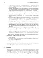
XFCD applications implemented by BMW include traffic, weather (precipitation,
visibility), and road conditions. Data elements collected include speed, acceleration,
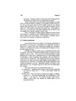
windshield wiper status, ABS signals, headlight status, and navigation data. Figure
11.2 shows the XFCD in-vehicle architecture, with the corresponding software
architecture shown in Figure 11.3.
BMW researchers have performed extensive analyses to understand the
trade-offs between the quality of traffic information and the necessary penetration
rates of equipped XFCD vehicles [7]. They assumed a period of 10 minutes for
detection of a traffic incident, which is seen as satisfactory precision for reporting on
262 Extending the Information Horizon Through Floating Car Data Systems
traffic conditions. One factor affecting needed penetration rates is traffic volume.
For example, mean passenger car volumes of 1,000 cars/hour require penetration
rates of 3.8% to reliably detect an incident (reports from at least three XFCD vehi
-
cles) within 10 minutes. The necessary penetration rates are halved if a 20-minute
detection period is allowed.
11.5 European FCD Activity 263
Message management,
transmission
Event x
Event y
Winding roads,
intersection, parking,
refueling,
Rain sensor
Speed
Wiper
Hazard lights
Gear
Doors
Indicator
Fog light
Acceleration
Airbag
ABS
ASC
DSC
Road-
category
Steering angle
Brake
Friction
Navigation
data
Light
Crash
Temperature
Data
preprocessing
SSI sensor
interface
Figure 11.2 XFCD in-vehicle system architecture. (Source: BMW Group.)
Transmission via the
best suited network
Packaging
transmission
Announcement
decision-making
Data preprocessing,
event detection
Data standardization
Vehicle-component
data collection
Transmission
XFCD-Unit
Standardized
sensor
interface
Vehicle sensors
Information transmission
Generation
Management
Event detection
Standardized data
SSI
Proprietary vehicle data
Vehicle onboard
network
Vehicle
data
interface
XFCD-
algorithms
Feedback-
channel,
prioritization
Communication
source: BMW Group
Figure 11.3 XFCD software architecture. (Source: BMW Group.)
The researchers applied their methodology to the Munich road network as an
example.
Results showed that, at a penetration rate of 9%, traffic conditions on 50% of
the secondary network are detected. If only the primary network is analyzed, a pene
-
tration rate of only 5% is sufficient to cover two-thirds of that network. Overall, the
analysis showed that an XFCD-capable fleet of 7.3% of the total number of passen
-
ger cars is sufficient to detect traffic conditions for over 80% of the main road net
-
work. For the overall German federal motorway network, analyses showed that
penetration rates of at least 2% are required for good incident detection at peak traf
-
fic times, and that satisfactory traffic information can be generated on 80% of the
motorway network at penetration rates of around 4%.
DaimlerChrysler CityFCD [12, 13] Daimler is similarly focused on reducing message
frequency through onboard measurement of link travel time and exception reporting
based on an onboard link time database.
Researchers have concluded that only 2–4 FCD messages are necessary to detect
the congestion fronts, and their analysis of necessary equipped-vehicle penetration
rates yielded results similar to those of BMW: a 1.5% FCD penetration rate gives
sufficient service quality in urban traffic. This relies also on the traffic center
employing a predictive interpolation algorithm to process the data in the most effi-
cient way and broadcast the predicted link information to the all other FCD vehicles
to update their databases.
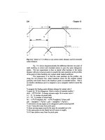
Each CityFCD vehicle measures its travel time on a network section and makes a
decision as to whether to transmit this data to the FCD service center or not, based
on the previous information received via broadcast. As shown in Figure 11.4, the
data broadcast from the FCD center contains both the threshold value and the travel
time for the upcoming road section (T
P
). The travel time for the upcoming road sec-
tion can be used as an input to onboard.
Dynamic Route Guidance (DRG) Systems In terms of communications factors, this
optimized message generation process was shown to reduce the amount of messages
264 Extending the Information Horizon Through Floating Car Data Systems
Time axis
ttՆ
out
DRG-vehicle
Broadcast travel time:
T
P
TfT
PP
FCD
=( )
FCD center
Figure 11.4 Broadcast of travel time data in the DaimlerChrysler CityFCD approach. (Source:
DaimlerChrysler AG.)
by a factor of 40. Candidate communication channels for data outbound from the
vehicle are GSM point-to-point, SMS, DAB, and GPRS. Data inbound to the vehicle
would be transmitted via broadcast.
11.6 FCD Projects in the United States
As in Europe, both public- and private-sector FCD initiatives are under way, some
of which are outlined here.
11.6.1 U.S. DOT VII
At the national level, the U.S. DOT is working with car manufacturers and state
DOTs to explore VII, as described in Chapter 9. VII applications focus on localized
services, such as intersection collision avoidance, and network-oriented services
that focus on overall regional conditions. FCD is seen as key to the latter.
While safety applications are seen as the eventual goal, it is also a longer term
goal and the VII program recognizes that various stepping stones must be in place to
get there. FCD techniques are seen as part of the early VII rollout, as it is less com
-
plex technically than advanced safety applications. Further, FCD lends itself to
retrofitted equipment more than many other cooperative vehicle-highway applica-
tions, and this in turn facilitates accelerated market penetration. This offers the
potential to demonstrate clear system benefits in the near term, which is essential to
build public and congressional support for further deployment.
State DOTs participating in VII discussions see the potential for FCD to save
them money in the long term: to the degree FCD is successful, they can reduce their
investments in fixed roadside and in-road traffic and weather sensors.
At the current early stages of VII, no FCD work is under way, but operational
test projects are being planned.
11.6.2 I-Florida
The U.S. Federal Highway Administration and Florida DOT are cofunding an
“Infostructure Model Deployment” that addresses a comprehensive range of trans
-
portation information collection and management. Experimentation with FCD
techniques is one of several project components.
FCD has the potential to be particularly effective in emergency evacuation situ
-
ations, which Florida has to deal with all too frequently in hurricane season. The
same is true at a national level during and after a major terrorist attack, as a compo
-
nent of homeland security.
11.6.3 Ford FCD Experiments [14, 15]
In recent years, Ford has become a very active player in experimenting with FCD
techniques. A partnership with the Minnesota DOT is currently under way, as well
as fleet testing in the Detroit area.
Minnesota The Minnesota project calls for 50 state police cars, ambulances
and state-owned cars and trucks to be outfitted with sensing devices to collect
11.6 FCD Projects in the United States 265
traffic and weather-related data. Data elements include vehicle speed, location,
heading, windshield wiper operation, headlight status, outside temperature, and
traction control system status. The information will be transmitted to the
condition acquisition reporting system for state roads. Based on data analysis,
key information will be derived and distributed to highway message signs,
511 telephone services, and related Web sites. Vehicles are expected to begin
reporting by late 2004 throughout the Minneapolis/St. Paul metropolitan area.
Minnesota DOT sees significant public sector benefits from the data collected,
such as the following:
•
Decreased time needed for emergency response;
•
Improved traffic management;
•
Improved road maintenance;
•
Improved identification and location of incidents;
•
Decreased cost to collect data, relative to existing techniques using roadside
infrastructure;
•
Expanded data collection coverage to all roads traveled by vehicles equipped
with the system;
•
Enhanced data quantity and quality due to fusion of data from multiple
sources ( such as inductive loops, road/weather information systems, vehicles,
and cameras);
•
Improved ability to specifically target the warnings and advisory messages to
drivers (in vehicles equipped with the system) as they approach the conditions
identified.
For incident detection and traffic management, MnDOT engineers see the fol-
lowing FCD data elements as useful:
•
Travel times between major junctions (for reporting travel times);
•
Abnormally slow travel on freeways (indicating stop and go conditions);
•
Alternating acceleration and deceleration on freeways (indicating stop and go
conditions);
•
Numerous indications of significant acceleration and deceleration on freeways
in a general vicinity (indicating congestion shock wave condition);
•
Abnormally slow travel on nonfreeways (indicating congested conditions);
•
Abnormally long stopped condition in one vicinity on nonfreeways (indicating
congestion at a traffic signal, signal malfunction, or incident).
Road maintenance mangers within MnDOT expect to benefit from data rel
-
evant to icing (ABS or traction control activation, windshield wiper status,
ambient air temperature, humidity), which can be fused with other data to direct
winter maintenance crews more effectively to needed areas. Also, pavement con
-
ditions can be indicated by frequency, amplitude and rate data from vehicle
suspension components.
266 Extending the Information Horizon Through Floating Car Data Systems
Detroit Ford is also equipping a fleet of vehicles in the Detroit area near its
headquarters with data reporting capability. This includes more than 20 employee
shuttle buses that operate in the area, as well as 15 area police cars.
11.6.4 Indiana Real-Time Transportation Infrastructure Information
System [16–18]
ZOOM Information Systems, under a grant from the state of Indiana, is developing
a real-time transportation infrastructure information system (RTTIIS) based on
FCD techniques. Other partners in the effort include Ford, Boeing and Purdue Uni
-
versity, with Indiana DOT and the Federal Highway Administration (FHWA) pro
-
viding requirements inputs for the project.
RTTIIS objectives are to collect road condition, traffic, hazard, and vehicle data
in real-time, nonintrusively, and in a cost-effective manner, from road users as they
go about their daily business. Processed information will then be provided to public
agencies, fleet managers, and back to the drivers themselves.
Plans call for RTTIIS to be based on an open architecture. Demonstration applica
-
tions will cover a diverse range including: driver information; traffic management;
roadway condition and repair; operations, public safety and crash prevention; fleet
management; law enforcement; homeland security; and defense.
Initial configurations will contain satellites, both broadcast and two-way, as
key elements, although many communication channels will be supported for spe-
cific applications.
The work will focus on four research subprojects addressing the following ques-
tions:
•
How can current and new vehicle sensors and systems be used to identify
road, traffic, vehicle data and other characteristics onboard?
•
How can this information be transmitted reliably and bidirectionally to mil
-
lions of vehicles?
•
What is the best architecture and mechanism for storing, aggregating and
accessing the data in an open way that is in line with VII principles?
•
How can this multivehicle information be analyzed to determine road, traffic,
and vehicle information and report or display it in a way that is actionable?
The RTTIIS project began in May 2004 with architecture definition. The
21-month project will culminate with an end-to-end, limited functionality system
demonstration, which is intended to lead to more extensive deployment.
11.7 Overall FCD Processing Picture [19]
Figure 11.5 captures most facets of the discussion above by showing the overall data
flows that may occur in a floating car data processing operation. The left-most box
labeled “vehicle” shows vehicle sensors feeding an onboard data collection system,
which is generating probe messages based on comparing current data with the
onboard database. Probe messages are sent to an onboard communications device
11.6 Overall FCD Processing Picture 267
to be sent outward to the probe processing center. The land-side processing function
receives data from many vehicles, processes the data, and fuses it with other data
sources to deliver processed probe data to application providers and eventually to
end users. Data flowing back to vehicles from the land-side processing center
updates their onboard databases and manages message flow. Processed probe data
also flows back to the vehicles, which is then used by onboard applications to deliver
information to the driver and/or support vehicle systems.
11.8 Looking Forward
How might information derived from FCD techniques become a standard part of
our transportation experience? With momentum in both the private and public sec
-
tors, it is likely that FCD systems will evolve gradually. It is certainly fortuitous that
fleet penetrations on the order of 2% or less are sufficient for good traffic and
weather data. The degree to which governments such as Sweden and the United
States fund early deployment activities, as they have indicated, will be key to creat
-
ing a critical mass of reporting vehicles.
Private-sector momentum also comes from the larger telematics industry, which
seeks to provide a wide array of services to drivers; in fact, most experts agree that no
single telematics application will present a sufficient business case and therefore pack-
ages of services are the way forward. Further, the car industry seeks to have continuing
connectively to vehicles for purposes of diagnostics and software updates. Therefore,
there seems to be significant motivation to create a “data pipe” to and from vehicles in
coming years.
268 Extending the Information Horizon Through Floating Car Data Systems
Vehicle
Other end users
Other
vehicles
Land-Side Processing
Other data sources
Vehicle
sensors
Probe
processing
center
Onboard
communication
device
Onboard
data
collection
system
Supplementary data
Raw
sensor
data
Transmitted
probe
message
Processed
probe
data
Services/
Information
Probe
commands
Onboard
database
Probe
commands
Database
updates
Application results (based
on processed probe data)
Application
results
Onboard
applications
Probe message
Reference
data
Application
providers
Data
message
processing
operation
Database
updates
Public
agencies
PDAs
and 3G
phones
Road
authorities
PolicePolice
Outbound
data
message
Received probe
messages
Weather
services
Figure 11.5 Typical FCD data flows. (Source: R. Weiland, Weiland Consulting.)
The role of consumer electronics and telecommunications players is also key.
For instance, Motorola is working within the Ford FCD project to demonstrate the
cell phone technology that could bring FCD-derived information inside the vehicle,
and Nextel is working on developing the wireless backbone for the system.
In fact, although not discussed above, another precursor to fully vehicle-based
FCD is GPS-enabled cellphones. Such units can provide speed, location, and direc
-
tion; if they were to report data when speeds represented roadway travel, a basic
picture of travel patterns could emerge.
From the public sector perspective, state DOTs see FCD as highly valuable in mon
-
itoring traffic and road conditions in real time, so as to better manage road and traffic
conditions and provide information to the public. They see the possibility for signifi
-
cant cost savings, as FCD information begins to obviate the need for expensive
roadside sensors.
As seen from the projects in Europe, first generation FCD systems are now in oper
-
ation. Second generation systems that are more commercially viable are expected to be
introduced within 2–3 years.
The BMW analyses referred to in Section 11.4.2 offered three scenarios as illus
-
trations of how next generation FCD systems might come into widespread use over
the long term [11]. The most conservative scenario calls for allowing natural market
forces to lead. Here, it was proposed that possibly 15% of new mid-size through
luxury vehicles sold would be XFCD-equipped by 2015, which would represent
4.3% of the total passenger car fleet at that time. The penetration level would be
sufficient to provide modest performance in FCD-based data collection. Another
scenario envisioned a coalition of German auto manufacturers, which together
would advocate and stimulate the creation of XFCD capable vehicle fleets. Under
this scenario, it was estimated that one-third of new mid-size to luxury models sold
are equipped with XFCD by 2015, which would then comprise 10% of the total
passenger car fleet. Based on their analyses reviewed above, 10% market penetra-
tion would be sufficient for very good performance in traffic data collection. The
third and most optimistic scenario called for governments to join with vehicle man
-
ufacturers to promote XFCD. Here, penetration rates of 20% of all passenger cars
could be expected by 2015, enhancing performance even further.
References
[1] Jenstav, M., “OPTIS—The Swedish FCD Project,” Proceedings of the 2003 ITS World
Congress, Madrid, Spain, November 2003.
[2] Breitenberger, S., “Extended Floating Car Data—An Overview,” Proceedings of the 10th
ITS World Congress, Madrid, Spain, 2003.
[3] accessed September 24, 2004.
[4] Wada, K., “Research, Development, and Field testing of the Probe Car Information System
(III),” Probe Car Project Office, Association of Electronic Technology for Automobile Traf
-
fic and Driving (JSK).
[5] Sarvi, M., et al., “A Methodology to Identify Traffic Congestion Using Intelligent Probe
Vehicles,” Proceedings of 10th World Congress on Intelligent Transport Systems, Madrid,
Spain, 2003.
[6] “Using Phones to Monitor Road Traffic,” , September 6,
2004.
11.8 Looking Forward 269
[7] Breitenberger, S., et al., “Traffic Information Potential and Necessary Penetration Rates,”
Traffic Engineering and Control, , December 2004.
[8] Private communication with Dr. Ralf-Peter Schafer, Institute of Transport, German Aero
-
space Center.
[9] “OPTIS: Optimized Traffic in Sweden Final Report,” version 1.6, Swedish National Road
Administration.
[10] accessed May 22, 2004.
[11] , accessed December 12, 2004.
[12] Demir, C., et al., “FCD for Urban Areas: Method and Analysis of Practical Realizations,”
Proceedings of the 10th ITS World Congress, Madrid, Spain, 2003.
[13] Demir, C., et al., German patent publication DE 102 611 72 A1, :
Verfahren und System zur zentralenbasierten, zeitlich vorausschauenden StÃrungserkennung
durch StÃrflanken-Detektion mittels abschnittsbezogener ReisezeitschÃtzung, day of notifica
-
tion: 12.20.2002.
[14] “Ford And Minnesota DOT Kickoff Road-Vehicle Communications Project,” IVsource.net,
June 11, 2004.
[15] “Ford Launches Intelligent Highway Revolution: “Smart Vehicles” Transmit Where and
How They Are,” Ford Motor Company press release, February 26, 2004.
[16] “White Paper: Real-Time Transportation Infrastructure Information System,” Zoom Infor
-
mation Systems, June 14, 2004.
[17] , accessed September 22, 2004.
[18] “Floating Car Data: Zoom Information Systems Enters the Fray,” ,
August 2004.
[19] Private communication with Richard Weiland, Weiland Consulting.
270 Extending the Information Horizon Through Floating Car Data Systems
CHAPTER 12
IVs as Human-Centered Systems
This chapter brings together several topics that have in common “the driver” but
are otherwise somewhat divergent. First, there is the driver as customer—what are
their perceptions of ADAS, and their acceptance or interest in the systems based on
those perceptions? Then there is the driver as system operator—what is the nature
of driving and how might human and machine work together most effectively?
Finally, there is the driver as a key, and fallible, player in the road-vehicle-driver
triad—how can drowsy or distracted drivers be detected by vehicle systems, and
what countermeasures can be applied to maintain safety?
The human factors issues that are invoked by these topics involve in-depth
expertise, complex questions, and detailed research beyond the scope of this book;
instead, the intent here is simply to introduce the reader to the issues.
Although there has been some outcry that the role of the driver is not adequately
addressed when it comes to IV systems, in reality these systems are inherently
human-centered. They must be, because of the commercial nature of most vehicle
sales. Cars are a consumer product; customers must be satisfied for a product to be
successful. Poor design and product debacles must be avoided at all costs because
the company’s brand is at stake. In fact, this imperative creates such a high standard
that significant time is added to the product development process before introduc-
tion specifically to address user issues. As noted in [1], “Future active safety systems
will need to be transparent to the driver until they are absolutely needed. The key is
to allow the driver to drive the car as the driver wants and only give assist when
needed.”
The same is true to a lesser degree for truck and bus drivers—they must have at
least a somewhat favorable opinion of a driver support system for it to be most
effective. For instance, trucking companies considering new systems such as lane
departure warning typically rely heavily on driver’s opinions, based on a few evalu
-
ation units, before making major investments to equip the entire fleet.
In essence, then, the driver is the water we IV fish swim in. While overt discus
-
sion of driver issues may not always be obvious, in fact driver needs and issues
underlie every decision made in system design and development.
It is also my conclusion that, in general, IV-related human factors issues cannot
be productively addressed at a generic functional level. Instead, very specific func
-
tional aspects must be defined in an iterative process between engineers and human
factors experts for all of these systems.
This chapter surveys issues and ongoing research in these topic areas and is
organized as follows:
271
•
Driver perception and acceptance (user preferences, understanding of systems,
perceived system benefits and drawbacks);
•
Driverology (how do normal drivers drive in everyday situations?);
•
Driver-vehicle interface (warning modes, learnability, comprehension);
•
Driver-vehicle symbiosis (shared control);
•
Driver monitoring and support (driver alertness, driver distraction, workload
support, older driver support systems).
12.1 Driver Perception and Acceptance [2]
Assessing driver perception of IV systems and attempting to predict driver accep
-
tance is a challenging arena with high stakes for the car companies. Customer reac
-
tions to such systems are subjective, information presented may not be absorbed or
understood correctly, and a very sophisticated system can be perceived as “dumb”
based on only a few anomalous experiences.
Further, drivers must not only understand and use a system properly, but they
must perceive that the assistance provided is worth what they paid for it.
For more advanced functions such as LKA, a balance much be achieved between
“over-trust” and “under-trust”—too much trust in the system creates dependence
(and could reduce vigilance) and if there is not enough trust in the system, the prod-
uct is not used and the customer may feel cheated.
It is also a fact of life that every driver-assistance system will have some limita-
tions. For instance, LDWS may not work when lane markings are completely
absent, lidar-based ACC systems may disable in heavy rain, and in cluttered envi-
ronments obstacle detection systems may not correctly interpret the situation, lead-
ing to either false alarms or missed detections. Generally speaking, more robust
systems could always be built, but at increased cost. Therefore, as research results
move into advanced development and products are defined, key questions that must
be addressed include the following:
•
To what degree will drivers understand system limitations?
•
To what degree will they accept (forgive) these limitations?
•
Will the system be seen as valuable even with these limitations?
With regard to user perception, there are two key categories: those who are
aware of the systems but have not experienced them, and direct users. Because early
systems such as ACC have begun to play a role in advertising for new vehicles and
the news media covers advanced system demonstration events, members of the pub
-
lic have generally formed opinions of these systems. Their perceptions are important
to the eventual market success of specific products.
Automaker’s experience with ACC provides a promising indication. While
hard data is closely held, all indications are that, with well over 100 million
vehicle miles traveled by ACC-equipped vehicle owners, no incidents of serious
concern have occurred. ACC satisfaction levels over 70% have been reported in
driver surveys.
272 IVs as Human-Centered Systems
Various assessments of public knowledge and perceptions of IV systems have
been conducted and some are reviewed here.
12.1.1 Perceived Positives and Negatives of ADAS Systems [3]
A study conducted by the Technical University of Delft in 1999 provides a good
view into attitudes amongst average drivers at that time. Almost 500 Dutch drivers
participated in the survey, which focused on obstacle detection systems, collision
avoidance systems, adaptive cruise control, and the automated highway system.
Participants in the survey received a basic description of each system, but had not
experienced the systems directly. The results as shown in Table 12.1 are telling. On
the negative side, distrust in the system operating correctly is obvious, such as con
-
cern that the systems will fail or brake unnecessarily. There is also strong opposition
12.1 Driver Perception and Acceptance 273
Table 12.1 Opinions on Driver-Support Systems
Obstacle Detection System
Positive aspects Negative aspects
Increased traffic safety 60% Decreased traffic safety 5%
Encourages positive
behavior changes
46% Decreases attention 44%
Less attention required
for driving
5% System is irritating 41%
Reduced collision risk 42% System can fail 39%
System startles driver 25%
Collision Avoidance System
Positive aspects Negative aspects
Increased traffic safety 42% Decreased traffic safety 12%
Less attention required
for driving
7% Decreases attention 32%
Reduced collision risk 58% System takes over control 65%
Braking at dangerous
moments
51%
Braking at unnecessary
moments
43%
Adaptive Cruise Control
Positive aspects Negative aspects
Increased traffic safety 45% Decreased traffic safety 9%
Improved traffic flow 47% System takes over control 56%
Impossible to drive fast 15%
Unwanted headway 27%
Braking at dangerous
moments
70%
Automated Highway System
Positive aspects Negative aspects
Always constant speed 40% Decreased traffic safety 5%
Less attention required
for driving
21% System takes over control 56%
Improves traffic flow 65% System takes away the
fun of driving
39%
Saves energy 43% Difficulty merging in and
out of traffic
43%
Source: Hoedemaeker, 1999.
to a computer-based system taking over control of the vehicle. Concern over being
startled by collision alerts was also high, highlighting one of the key challenges for
system designers in defining warnings that are attention-getting without creating
panic.
On the positive side, participants clearly saw the potential for improved safety
and understood the traffic flow benefits offered by ACC and AHS.
Unfortunately, it is also the nature of the beast that incorrect or exaggerated
opinions can exist in the public mind. A prime example from this study is the belief
that ACC would prevent fast driving—showing an insufficient knowledge of such
systems (particularly their on/off switches!).
12.1.2 User Perceptions Assessed in STARDUST [4, 5]
In the STARDUST project, user responses to ACC, stop-and-go ACC, intelligent
speed adaptation, lane keeping, and CyberCars were assessed via questionnaires,
field trials, and driving simulators. From a human factors perspective, one particular
focus was to understand how drivers adapt to these systems within urban traffic
flows in terms of the learning phase and long-term effects. Some results of simulator
experiments with ACC and ISA systems are described here as examples of this work
(the impact of lane-keeping systems to improve traffic flow in narrow lanes was
reported in Chapter 9). User perceptions of the benefits and drawbacks of these
systems are also reviewed.
ACC System The simulator trial with ACC indicated that drivers chose
significantly lower top speeds when using ACC. The ACC System implemented on
the simulator emulated the characteristics of early ACC systems introduced to the
market. Drivers also used the brake and accelerator pedal more often and with more
force compared to driving without the system. Researchers theorized that this was
related to a possible lack of faith in the technology, and/or drivers experimenting
with the system to better understand its function. Indeed, post test interviews
indicated that abrupt braking events to disengage the ACC were related to distrust
of the system. Drivers were expecting earlier braking than the system provided, and
when they finally chose to intervene, more forceful braking was used.
The simulator studies also showed that drivers chose longer headways when
driving with ACC than without. In terms of driver workload, driving with the ACC
system at highway speeds was perceived as more mentally challenging (higher work
-
load) than driving with ACC in low speeds. A longer exposure time to the technol
-
ogy could potentially affect this factor.
ISA System Simulator trials of ISA were conducted with a haptic-feedback ISA
system in which the accelerator pedal became resistant when the speed limit was
exceeded; further, the driver received a noticeable “kick” under the foot when the
speed limit was passed. Results showed a significant reduction in top speed for the
urban settings studied, and less lane changing compared to a baseline condition
when on a motorway. Post test questionnaires showed some irritation with the
“kick,” but overall drivers found the ISA system to be useful.
The STARDUST experience also confirmed the general trend that participants
were more favorable towards a system after having experienced it (via a driving sim
-
ulator in this case) than before.
274 IVs as Human-Centered Systems
User Acceptance In a survey of almost 1,000 people conducted by the STARDUST
team, overall perceptions of the driver-assist systems examined were positive. The
strongest support was for ISA, ACC, and CyberCars, followed by stop-and-go ACC
systems and lane-keeping systems.
Respondents were queried about system benefits in several dimensions. They
saw ISA and CyberCars as the strongest contributors to safety. CyberCars were seen
as having the greatest positive effect on congestion relief. Both ACC and CyberCars
were seen as being beneficial to the environment, with ACC viewed a winner in
terms of fuel consumption. In terms of public funding, lane keeping, stop-and-go
ACC, ISA, and CyberCars were seen as imposing high costs. This last item is curi
-
ous, in that lane keeping and stop-and-go ACC essentially require no modifications
to the infrastructure.
12.1.3 User Perceptions of ACC Users [6]
In a more focused project, the Dutch Rijkswaterstaat conducted a survey of 76 own
-
ers of vehicles equipped with ACC, augmented by interviews with 13 ACC users.
The results showed that a period of adjustment is necessary when first encoun
-
tering ACC. Once accustomed to the system, drivers whose driving style was typi
-
cally relaxed tended to brake more often and accelerate less often, whereas
aggressive drivers accelerated more. In addition to motorway use, some drivers also
used the system on nonhighway roads where speeds of over 80 kph were allowed,
and in some cases on 50 kph roads.
Almost all drivers were positive about ACC because it increased driving com-
fort. The majority thought ACC improved road safety, and many said using ACC
resulted in a more even speed, less speeding, calmer driving, greater following dis-
tance, increased alertness in traffic, and less frequent passing. At the same time, a
considerable number said ACC sometimes led to reduced concentration.
12.2 Driverology
Understanding the driver-system interaction for IV systems relies on a fundamental
baseline—how do drivers drive in normal situations? How do they make their
moment-to-moment decisions in vehicle operations and their longer term trip-ori
-
ented decisions? Driverology is one term applied to these questions.
We know a great deal about the results of driver errors that result in crashes, but
there has been a dearth of knowledge about ways in which drivers successfully oper
-
ate their vehicles. For instance, we know relatively little about successful avoidance
maneuvers, near-crashes, and driver errors that do not result in crashes. Here we
review several approaches that are being used to expand the knowledge base in
these areas.
12.2.1 Driving Simulators
One of the key tools used in recent years to understand driving is driving simulators.
These facilities have become very sophisticated in creating a realistic virtual envi
-
ronment. The driver sits within an authentic vehicle cockpit and has a full view of
animated traffic, to include side and rear mirrors. In the most sophisticated systems,
12.1 Driver Perception and Acceptance 275
the traffic responds to the driver’s actions as would happen on the road. An endless
variety of road configurations can be displayed.
Using simulators, critical maneuvers or crash situations can be presented to the
driver and their simulator vehicles can be equipped with crash avoidance functional
-
ity to enable the evaluation of functional concepts as well as driver-vehicle interface
approaches.
In advanced simulators, the vehicle itself is on a moving base so that kinematics
can be directly experienced by the driver to increase realism. One such simulator is
the National Advanced Driving Simulator at the University of Iowa, which came
on-line in the late nineties to serve U.S DOT and industry needs and was considered
state-of-the-art at the time. However, several car companies have since implemented
even more advanced simulators, the most recent of which being Ford’s VIRTTEX,
whose main purpose is to study driver workload and distraction issues that can arise
with in-vehicle electronic devices [7].
12.2.2 Test Track Evaluations
Evaluating driver-system interactions on test tracks is another research method, but
of course challenges exist in creating realistic crash scenarios that are not in fact dan-
gerous to the test subjects. For evaluation of forward collision warning systems, for
instance, researchers within the U.S. CAMP project constructed a long boom, at the
end of which was attached the sliced-off rear portion of a vehicle, including the back
wheels. The boom was designed to be energy-absorbing in the event of crash contact
and was towed by a regular vehicle ahead of the test vehicle. This enabled research-
ers to initiate hard braking on the leading “vehicle” and assess various warning
modes for drivers in the following vehicle without putting them at risk.
Further, at a U.S. DOT testing facility, a test track has been configured with a
foam wall alongside the test track roadway to emulate the concrete barriers com-
monly found on highways. Drivers are asked to “steer at the last second” to deter
-
mine a safety margin for providing road departure warnings.
12.2.3 U.S. DOT Naturalistic Driving Study [8]
Of course, even the most “realistic” simulators and test track experiences are not
“real.” Possibly the richest data can be gathered by monitoring drivers as they drive
on actual roads. The drawback here is that the incidence of safety-critical events is
very low on a per-vehicle basis. Therefore, if such data is to be collected, many vehi
-
cles have to be equipped.
Such an ambitious endeavor was initiated in 2002 by the U.S. DOT. In the
agency’s naturalistic driving study, 100 vehicles were equipped for one year with
unobtrusive instrumentation to observe regular drivers on actual roadways. In fact,
this was the largest instrumented vehicle study of its type conducted to date world
-
wide. The U.S. DOT’s intent was to deepen its scientific understanding of how driv
-
ers drive in normal situations to provide a baseline for other research.
The vehicles are equipped with video cameras to monitor the driver’s face and
body movements, as well as the forward traffic situation. Additionally, a significant
amount of quantitative data is collected regarding vehicle parameters. Given the
large number of equipped vehicles and their time on the road, the resulting data set is
276 IVs as Human-Centered Systems
expected to exceed three terabytes. It will serve as a rich resource for researchers for
years to come.
Researchers report that, in addition to significant amounts of basic data, over
40 crashes occurred in the equipped vehicles, providing a unique opportunity to
understand crash dynamics. Over 300 near crashes occurred as well. Full analysis of
the data is expected to be completed in late 2004.
12.2.4 Driver Performance in Traffic [4]
As noted in Chapter 9, driver performance in traffic is a key contributor to conges
-
tion. IV systems offer an opportunity here. In queuing situations, such as at traffic
signals and motorway traffic jams, vehicle-level delay occurs in starting movements
because of driver reaction time, maneuver delays, mechanical delays and human
error. Driverology research conducted in the STARDUST program focused on
quantifying such delays. Results showed that start delays on motorways were signif
-
icantly higher than those on urban streets. The mean start delay on motorways was
1.27 seconds, compared to 0.93 on urban streets. This is to be expected, because
drivers are in a relatively familiar and predictable situation when at a traffic signal,
compared to the more or less random movements when in stop-and-go motorway
traffic. This data led researchers to conclude that driver-assist systems such as
stop-and-go ACC would likely have greater utility on motorways as compared to
urban street applications.
STARDUST researchers also measured headway choices using a vehicle instru-
mented with a lidar rangefinder. The data collection covered urban motorways,
urban arterial roads, and city streets in Oslo, Paris, and Southampton. The analysis
focused on low-speed traffic behavior, particularly in stop-and-go traffic. Key
parameters collected were time gap, distance gap, acceleration, deceleration, brak-
ing frequency, start delays, and stopping distance gaps. Results from 65 hours of
driving included the finding that time gaps decreased as following speeds increased
when below 60 kph and stabilized above 70 kph and further, that time gaps had
greater variability in the lower speed range.
12.3 Driver-Vehicle Interfacing
The driver-vehicle interface is a core aspect of the IV system. Here we review driver
warning modes and key factors for DVI subsystems and provide some particular
examples as to the learnability of such systems.
12.3.1 Driver Warning Modes
For active safety systems, a wide variety of driver warning modes have been noted in
describing ADAS systems in previous chapters. They are:
•
Audible;
•
General;
•
Directional;
•
Visual;
12.3 Driver-Vehicle Interfacing 277
•
Dashboard icon;
•
Heads-up display;
•
Haptic;
•
Resistance in accelerator pedal;
•
Resistant torque in steering wheel;
•
Tightening of shoulder belt;
•
Deceleration sensed when light braking applied;
•
Seat vibration;
•
Steering wheel vibration.
Significant research has been conducted worldwide in understanding how to
best present information to the driver. This is a major research question within the
GM-U.S. DOT ACAS project, for instance. There is no single “best way”—the DVI
must be defined in the context of the specific functional goals of a driver support
system.
12.3.2 Key Factors in Successful DVI
The European 5FW RESPONSE project defined six factors important to the success-
ful interaction between the driver and active driver-assistance systems [9]. These are
described as follows:
•
Perceptibility: Translating the system function into an accurate mental model;
•
Comprehensibility: Understanding the system function, operation, and situa-
tional limits;
•
Learnability: Ability of the driver to quickly and accurately learn to control
the system and assimilate information provided by the system;
•
Trust: The degree to which the driver believes the system will perform its func-
tion;
•
Misuse potential: The possibility of drivers choosing higher risk behaviors due
to the “safety net” provided by the system (also called “risk compensation”);
•
Error robustness: The ability of the system to maintain a safe state in the pres
-
ence of driver usage errors. Ideally, an error robust system will achieve the
driver’s intended result even with some degree of incorrect usage.
In Europe, current publicly funded research in DVI focuses in the 6FW AIDE
integrated project and the German INVENT program.
12.3.3 Learnability of ADAS [10]
Driver-oriented issues that must be addressed in the product design process include
learnability, the efficient perception and interpretation of warnings, and any modes
that could annoy drivers or provoke errors in use. INVENT researchers are seeking
to define simple, self-explanatory driver-assistance systems that prevent misuse but
are also robust if errors happen. Two representative systems have been implemented
on a moving-base driving simulator: a lane change assistance system and the traffic
congestion assistant.
278 IVs as Human-Centered Systems
To assess learnability, researchers are focusing on the following:
•
System-related criteria (fault-free and efficient operation; usage of all system
functionalities);
•
Safety-related criteria (safety-critical operation, safety-critical driving faults);
•
Driver-related subjective criteria (system acceptance; stable workload; subjec
-
tive assessment of comfort and safety).
Lane Change Assistant The lane change–assist system is less challenging in terms
of learnability, as its function is limited to providing information and warnings as
needed. It is only operating when the driver has activated the turn signal, so that the
driver intention to change lanes is clear, and he or she is already attuned to the type
of information being presented by the system. In the experiments, three warning
modes were used: an LED display in the side mirror, a warning sound, and tactile
feedback in the form of vibration of the turn indicator lever.
Subjects in the experiment drove for 20 minutes without the lane change assist
followed by 20 minutes with the system activated. The results were quite positive, in
that almost no user errors were made, turn signal usage increased, and the driver’s
subjective assessments were favorable.
Traffic Congestion Assistant The traffic congestion assistant (introduced in
Chapter 9) was chosen as an example of a system with a high level of automatic
vehicle control, which invokes a completely new and different experience for the
driver. The TCA provides longitudinal and lateral control on highways in congested
traffic situations. In the experiments, the low-speed control was combined with a
conventional ACC system to cover the complete speed range.
Driver errors were observed and classified into the following categories:
•
Operational errors in using the system;
•
Critical take-over situations;
•
Driving errors due to distraction effects while operating the system;
•
“False alarms” (driver takes over control unnecessarily, indicating mistrust);
•
Errors based on incorrect understanding of system functionality.
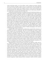
During the experiments, the researchers noted three sequential phases of
learning as shown in Figure 12.1. In the first phase, the drivers were becoming
accustomed to the TCA, making errors in its use as well as driving errors.
Because they were neglecting the primary driving task, more critical safety situa
-
tions occurred during this phase. Drivers rated this phase as stressful, an assess
-
ment that was supported by increases in measured heart rate. Researchers
concluded that this phase was completed by the end of the third lap in the simu
-
lated congested driving route.
Drivers began to show more trust in the second phase and showed indications of
becoming more accustomed to the “feel” of the system. This was indicated by a
decrease in the number of false alarms for some drivers. However, others continued
to be reluctant to rely on the system and continued to take over control when
approaching a vehicle ahead.
12.3 Driver-Vehicle Interfacing 279
The driver’s active engagement with the system decreased in the final phase,
showing adaptation of the driving behavior to the assistance function. At this stage,
errors in operating the system are largely acceptable and do not create safety-critical
distractions. Researchers noted that the driver’s subjective ratings of the system at
this phase became more positive.
Based on these and other results, INVENT researchers are working to define the
optimum “self-explanatory ADAS,” which requires a minimum amount of learning
from the driver and in particular eliminates learning modes which result in safety-criti-
cal traffic situations. Two approaches are being pursued:
•
A learning-adaptive tutor module giving the driver additional advice and
explanation according to the current stage of his or her learning;
•
A driver-adaptive feedback method based on driver-type categories. For
instance, feedback would be different depending on the driver’s attitude
towards technology.
By the end of 2005, the research team plans to complete design guidelines for
start-up instructions, online help, communicating system limits, error tolerance and
robustness, and strategies for prevention of misuse.
12.4 Driver-Vehicle Symbiosis
This section addresses various ways in which the driver and vehicle system can oper
-
ate in symbiosis to operate most effectively. ACC and safety systems are briefly
addressed, followed by a more in-depth look at driver effects when using lane-keep
-
ing assistance systems.
280 IVs as Human-Centered Systems
Average number of errors during experiment
0
1
2
3
4
5
6
Lap 1 Lap 2 Lap 3 Lap 4 Lap 5 Lap 6 Lap 7 Lap 8
Count
Operational error Misunderstanding of functionality
False alarm Critical take-over situation
Driving error while operating
Figure 12.1 Errors observed while drivers used the INVENT traffic congestion assistant in a driving
simulator. (Source: INVENT FVM.)
12.4.1 ACC Systems
When ACC is sold to a customer as an option on a new car, the buyer may watch
a video to explain the system and typically does an orientation drive with the
salesman. In fact, if “training” on the system requires more than this, customers
will balk.
It appears that the classic customer experience with ACC proceeds through sev
-
eral phases, which may be applicable to future ADAS systems, as well. During the
first several hours of using the system, the customer is learning the basic ACC func
-
tionality. Then, over the next several days of use, the customer tentatively uses the
system, gaining confidence and deepening their understanding. For the following
few weeks, the customer defers to system—when ACC is engaged, the driver takes a
secondary role. Finally, a steady state situation emerges in which the customer part
-
ners with system (i.e., the driver provides control inputs along with the ACC sys
-
tem). For example, the driver might accelerate when changing into an unobstructed
lane and then release the pedal to allow the ACC system to continue speed control.
12.4.2 Levels of Human-Machine Cooperation [21]
To frame the human-machine relationship for safety-assist functions, ARCOS
researchers in France have established three levels of human-machine cooperation:
•
The “meta level” focuses on a “perimeter of precaution” with a time scale of
approximately 3–15 seconds. Here, the goal is to assist the driver in situa-
tional awareness and perception of the traffic and road dynamics.
•
The “planning level” focuses on a “perimeter of cooperation” with a time
scale of approximately 1–3 seconds. Here, functions must be allocated
between the driver and automatic systems to maintain safe driving—the
driver still has time to respond when warned of a situation and at the same
time the safety systems may be enhancing vehicle functions such as braking
ability or seat belt tension.
•
The “action level” focuses on a “perimeter of safety” with a time scale of less
than one second. Here, automated intervention is invoked to avoid a crash.
12.4.3 Driver Vigilance with Advanced Assistance Systems [11]
Developers of the Honda intelligent driver-support system, which provides
lane-keeping assistance and ACC in highway conditions, have performed extensive
testing of driver vigilance while using the system. The system has been available on
the Accord in Japan since 2002.
At first glance, it would seem that simultaneous operation of LKA and ACC
would result in a drop in the driver’s vigilance, because much of the lateral control
and almost all of the longitudinal control is handled by those systems in steady state
conditions. In case of an emergency, however, the driver’s attention is needed
instantly to respond to situations beyond the functional limitations of the systems,
such that vigilance must be maintained. In designing the HIDS, Honda’s aim was to
define an assistance system that did not result in loss of vigilance by creating a
“copilot” system in which driving tasks are shared between the driver and the
system.
12.4 Driver-Vehicle Symbiosis 281