Intelligent Vehicle Technology And Trends Episode 1 Part 8 docx
Bạn đang xem bản rút gọn của tài liệu. Xem và tải ngay bản đầy đủ của tài liệu tại đây (358.28 KB, 20 trang )
•
Backup/parking assist;
•
Night vision;
•
Adaptive front lighting;
•
ACC;
•
Forward collision warning;
•
Safe gap advisory;
•
Rear impact countermeasures;
•
Braking assist (precrash);
•
Forward collision mitigation/avoidance;
•
Pedestrian detection and warning.
Safe speed applications, such as ISA, are covered in Chapter 9 as they typically
rely on cooperative system elements. Platooning, the ultimate form of longitudinal
sensing and control, is addressed in Chapters 9 and 10.
For each application area above, a general introduction and descriptions of rep
-
resentative systems are provided. A discussion of market aspects is also provided in
some cases, depending on the degree to which a particular application has entered
the market. Evaluation projects and significant R&D relating to some of the key
application areas are also described.
The chapter concludes with an overview of next generation longitudinal sensors
and some observations by the author.
7.1 Rear Sensing for Parking
7.1.1 System Description [1, 2]
Parking consists of short, low-speed maneuvers that may be to the front, rear, or
side. In Chapter 6 we saw that steering assist has been employed to assist drivers in
the complex maneuvering used for parallel parking. Longitudinally, the maneuver is
simple and the focus instead is on proximity sensing of nearby objects that are either
not directly viewable by the driver or the clearance distance is not apparent.
The market pull is strong for such systems, as many drivers are at their most
uncomfortable when operating their vehicle in a tight parking situation. While the
risk to life and limb is almost nil, the risk to paint and good relations with the own
-
ers of neighboring vehicles is at a critical level! Further, drivers are aware of the risks
and their own limitations in these situations and can easily understand the utility of
parking-support sensors.
Back-up sensors based on ultrasonic sensing, consisting of miniature bumper-
mounted sensors, have been in use for some time. These are first generation systems
that are limited by a short detection range (only a few meters).
In recent years, parking-assist systems have progressed such that data from
video, ultrasonics, and onboard processing are fused to provide sophisticated driver
advisory systems. For instance, supplier Valeo has developed its ultrasonic park
assist (UPA) system by integrating information from three previously separate sens
-
ing systems. When reversing, a rear-looking bumper-mounted wide-angle camera is
activated. The video images are processed, any distortion is minimized, and the
122 Longitudinal Sensing and Control Systems
image is presented to the driver on a dash-mounted LCD display. Data from a sec
-
ond source, the steering angle sensor, is interpreted to provide continuous informa
-
tion on the vehicle’s trajectory as it reverses and is represented on the display by a
series of colored “navigation” lines that the driver follows by turning the steering
wheel in the appropriate direction. Information from a third data source, the UPA
sensors, is accessed to provide closing distance to any obstacle to the rear of the
vehicle. This information is also processed and superimposed on the driver’s dis
-
play, both as spatially correlated colored bars and as numerical data. The measure
-
ment ranges from 2m down to 25 centimeters. If this point is reached, the “stop”
message is displayed. The intent of the UPA is to provide drivers an easy-to-use,
real-time display of the essential data they need to successfully complete common
parking maneuvers.
Use of short-range radar for rear sensing (and low-speed maneuvering in gen
-
eral) offers the advantages of greater accuracy in both the range and direction of
obstacles, as well as extended range. At ranges of 5m, radar systems can provide
obstacle detection with sufficient warning time to support speeds up to 7 mph.
Therefore, whereas ultrasonic sensors are useful in close-in parking maneuvers, the
extended range provided by radar supports drivers backing their vehicles in large
parking lots and driveways.
As radar costs gradually come down, radar-based parking aids are expected to
supplant ultrasonics to a large degree.
Parking-assist functions based on 24-Ghz short-range radar were demonstrated
at the 2003 ITS World Congress by the SARA Consortium. DaimlerChrysler and
BMW both had vehicles on display that were equipped with arrays of four radars in
each of the front and rear bumpers, allowing for comprehensive coverage ahead and
behind the vehicle. Small vertical posts were positioned a short distance from the
vehicle at heights that could not be seen by the driver once the vehicle was within a
meter or so. An audible alert was sounded when encroaching upon obstacles ahead,
and the brakes were applied when reversing towards obstacles behind, so as to
make them impossible to collide with. Encouragingly, experts at the event noted
that the radar units, even at this research stage, can be produced at a cost of approx
-
imately $25. While a full suite of these sensors at this price would still be considered
costly in automotive terms, the cost goals are seen as being within reach [3].
7.1.2 Market Aspects
Delphi is the market leader in first generation backup radars with over 300,000
units sold. Its Forewarn dual-beam radar back-up aid is scheduled to reach the mar
-
ket in model year 2006.
7.2 Night Vision
7.2.1 System Description [2, 4]
Night vision systems originally developed for military operations were adapted for
the automotive market by General Motors during the 1990s. The first system was
introduced on the company’s Cadillac brand in the middle part of that decade.
7.2 Night Vision 123
The Cadillac and other first generation night vision systems employ an infra
-
red camera operating in the far infrared region (over 1,000 nm). The forward
range of this type of infrared sensing is on the order of 500m, which is far
beyond the 150m range of typical headlights. Another approach, developed
more recently, uses active illumination—near-IR energy is projected from the
vehicle and the reflected energy is received and processed. Near-IR night vision
provides a more natural-looking image to the driver than traditional thermal
(far-IR) night vision and allows the driver to see “cold” objects such as trees and
mailboxes. The near-IR light is not visible to humans, so oncoming drivers are
not affected by the projected light. With active near-IR systems, the detection
range is less, however—on the order of 100m.
The infrared image is typically displayed on a small screen near the driver’s for
-
ward view. Some systems employ a dedicated screen atop the console and others use
a heads-up display. Infrared energy emanating or reflecting from pedestrians and
animals is clearly seen on the display.
With night vision, the driver’s ability to perceive the forward path is enhanced
immensely. Without night vision, the timing of a pedestrian coming within view of
the headlights may give the driver very little response time if an avoidance maneuver
is required, which could lead to a crash or loss of vehicle control. With night vision,
a potential obstacle is made visible with plenty of time to gracefully respond to the
situation. Depth perception is also enhanced. Further, night vision helps to detect
pedestrians and roadside objects when the driver’s vision is affected by the glare of
ongoing headlights.
7.2.2 Night Vision Systems
Some examples of night vision systems offered by automakers and suppliers are
given here.
Visteon’s Driver Vision at Night [5] Visteon’s Driver Vision at Night uses a
dedicated illumination source to cast near infrared light upon the road and an
internally mounted, near-infrared sensor to capture the road scene ahead of the
vehicle. This information is projected directly in front of the driver, thereby
supporting drivers in keeping their eyes on the road.
PSA Night Vision [6] A system developed automaker PSA uses an integrated
camera and emitter mounted inside the vehicle operating in the range of 700–1000
nm wavelength. IR energy at this wavelength is not affected by windshield glass.
PSA has also developed a passive night vision system operating in the 8,000–12,000
nm wavelength range that must be mounted outside the windshield. The company is
currently studying methods to analyze the infrared image to detect potential hazards
(such as pedestrians) and alert the driver.
Bendix XVision [4] The Bendix XVision system was the first infrared night vision
system designed for commercial vehicle applications. Their system, an adaptation of
the Cadillac system, consists of an externally mounted, roof-top far infrared camera.
This data is then transformed into a virtual image projected onto an in-cab heads-up
display mounted just above the driver’s line of sight. The driver glances at the
head-up display just like passenger car drivers glance at a rearview mirror. A 1:1
124 Longitudinal Sensing and Control Systems
viewing ratio is employed so that images depicted on the in-cab display unit will be
in identical proportion to the image as seen through the windshield.
When viewing the display unit, the driver sees a real-time, black and white,
thermal image of the road in which warmer objects—such as people or ani
-
mals—appear in shades of white, while cooler objects—like bridge abutments,
guardrails, or trees—show in darker shades of gray or black.
7.2.3 Market Aspects
Night vision is sold as an option on Volvo and Hummer automobiles, in addition to
Cadillac. Bendix is the only supplier of night vision systems to the heavy truck
industry. A new night vision system that also incorporates pedestrian detection
entered the Japanese market in 2004. This system, from Honda, is further described
in Section 7.10.
7.3 Adaptive Front Lighting (AFS)
7.3.1 System Description
AFS systems illuminate areas ahead and to the side of the vehicle path in a manner
intended to optimize nighttime visibility for the driver. Basic systems, already on the
market, take into account the vehicle speed to make assumptions as to the desired
illumination pattern. For instance, beam patterns adjust down and outward for
low-speed driving, while light distribution is longer and narrower at high speeds to
increase visibility at farther distances. More advanced systems also incorporate
steering angle data to illuminate a fixed auxiliary beam. These concepts are
illustrated in Figure 7.2.
Going one step further, advanced AFS systems use a swiveling lamp for the aux-
iliary beam. The lamp is controlled by a microcontroller linked to the vehicle’s data
7.3 Adaptive Front Lighting (AFS) 125
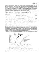
Night vision
range: 1,500 ft.
High-beam
range: 500 ft.
Low-beam
range: 350 ft.
Reaction time without XVision: 5.7 sec.*
Reaction time with XVision: 17 sec.*
*Assumes driving speed of 60 mph
Figure 7.1 Sensing range of Bendix XVision night vision system is far beyond typical headlights.
(Source: Bendix Commercial Vehicle Systems LLC.)
network with real time inputs from both the steering angle and vehicle speed sen
-
sors. The system aims to automatically deliver a light beam of optimal intensity to
maximize the illumination of oncoming road curves and bends.
The next generation of AFS systems will use satellite positioning and digital
maps so as to have preview information on upcoming curves. Headlights are then
aimed into the curve even before the vehicle reaches the curve, at just the right point
in the maneuver. The net effect is that the driver is presented with a more consistent
view of the road rather than unnecessary glimpses into the forest!
7.3.2 System Descriptions [1, 7]
Visteon’s system controls the forward illumination pattern based on data from a
steering wheel sensor, speed sensor, and axle sensors to direct the headlights in
real time. In the case of a vehicle turning a corner, for example, the outer head-
light maintains a straight beam pattern while the inner, auxiliary headlight beam
illuminates the upcoming turn (Figure 7.3). The system responds to vehicle
speed here as well.
Valeo’s development of AFS, which is a part of its “Seeing and Being Seen”
domain, provides another example. The company’s base system adapts the direction
and intensity of forward illumination to vehicle speed and road contours. In addi
-
tion to the main and dipped beams, an additional light source is integrated into the
headlamp at a fixed offset angle of around 35 degrees towards the nearside. This sec
-
ond light source provides automatic illumination of sharp road curves and intersec
-
tions at low to medium speeds, again based on steering angle and speed data. Valeo
asserts that such a system provides a 90% improvement in the driver’s view of the
peripheral area of the nearside lane.
7.3.3 Market Aspects [8]
These smart lighting systems have a market advantage relative to many IV safety
systems which are “silent” unless a crash is imminent—drivers can experience the
benefits of adaptive headlights every time they drive at night.
Market introduction of the advanced forms of adaptive headlights received an
enabling boost in 2003 when regulatory changes allowed the specification of intelli
-
gent lighting systems on new vehicles throughout Europe [9].
In 2004, vehicles with AFS systems (15-degree swivel range) included Acura,
Audi, BMW, Lexus, Mercedes-Benz, and Porsche. GM’s AFS system swivels the
lamp 20 degrees toward the outside and 5 degrees toward the center.
126 Longitudinal Sensing and Control Systems
Bending
Motorway
Cornering
Town lighting
Figure 7.2 Adaptive front lighting optimizes illumination based on speed and steering. (Source:
Visteon.)
7.4 Adaptive Cruise Control (ACC)
ACC eases the stress of driving in dense traffic by acting as a “longitudinal con
-
trol copilot.” As described in Chapter 3, ACC systems provide cruise control
and also track vehicles in the lane ahead of the host vehicle and adjust speed as
needed to maintain a safe, driver-selectable intervehicle gap. For reasons that
will follow, ACC comes in various “flavors” including high-speed ACC, low
speed ACC, and full-speed-range ACC.
This section begins with an overview of the sensing technologies and trade-offs
for ACC systems, which generally apply to forward collision countermeasures as
well. Individual system types, implementation approaches, and market aspects are
then reviewed.
7.4.1 ACC Sensor Technologies and Trade-offs
ACC sensors must detect range and range rate to vehicles in the forward path of the
host vehicle. To do this job, radar, lidar, and machine vision sensors are used. Their
characteristics are described here at a high level.
In the ideal world, a suite of multiple, complementary sensors would be used to
get the best performance, but this is currently cost-prohibitive. Therefore, tradeoffs
between system types are also discussed.
7.4 Adaptive Cruise Control (ACC) 127
Figure 7.3 AFS improves roadside illumination on curving roads. (Source: Visteon.)
Sensor technologies are described in relation to first generation high-speed ACC
systems, which are at a more mature stage than low-speed or full-speed range ACC.
Radar-Based ACC [5, 10–13] Radar-based ACC systems are offered by several
suppliers. Examples of ACC implementations are offered here, based on Bosch,
Denso, Renault, TRW, and Visteon systems. Obviously, the parameters involved in
such a system are numerous and only a few are covered here.
High-speed ACC systems operate within the 76–77 GHz frequency range and typi
-
cally use FM Continuous Wave, frequency shift keying, or pulse modulation. Forward
range of the Denso and Visteon designs is 150m, with others as short as 120m. An
important range factor is also the minimum range, which affects the radar’s utility at
short distances. Visteon’s system is specified at 1m minimum range, whereas the TRW
system minimum range is zero. Range resolution is another key factor, which can be
expressed in absolute terms (less than 3-m range resolution in the Visteon system, 5m
for the Bosch radar) or as ranging precision (stated as 5% by TRW).
Beamwidths are generally in the range of +/−5 degrees. The beamwidth of the
Bosch radar is +/− 8 degrees, and Denso’s radar is widest at +/− 20 degrees. In
some cases, the beam is designed to be wider (approximately 10 degrees) at short
range (less than 40m) and narrower (approximately 8 degrees) at long ranges. This
enables monitoring of near-distance “cut-ins” (vehicles in the adjacent lane sud-
denly moving into the host vehicle’s lane) while at the same time rejecting targets in
adjacent lanes in the far field.
Both mechanically scanned techniques and switched-sector beams are used to
enable radar sensors to determine azimuth information for forward targets. The
Delphi system used on Jaguar systems is a single mechanically scanned beam, for
instance. For switched sector beams, the number of beams is another factor. The
Visteon system uses two beams; Continental-Teves and TRW systems use three
beams; Bosch uses four beams; and Honda’s system uses five beams.
Elevation beamwidth is also important—too wide of an elevation beam will
result in radar returns from overhead structures, complicating the process of reject
-
ing false targets. Conversely, too narrow of a beam will degrade performance of the
system in detecting forward vehicles on vertically sloping roadways. + /− 2 degrees
is typical.
Lidar-Based ACC [13, 14] Lidar systems emit and detect near-infrared light at
wavelengths between 750 and 1,000 nm.
Switched-beam approaches are typically used for lidar. For example, Hella’s
ACC system uses a 16-beam lidar. Denso’s lidar achieves a wide scanning range by
using a rotating polygon mirror with various surface incline angles to achieve
two-dimensional laser scanning at a horizontal angle of up to ±18 degrees. Its laser
diode produces power of 34 watts, which extends the range out to 100m. Using
advanced time measurement circuitry, detection of forward objects can be accom
-
plished with a range error of only a few centimeters at this range.
Vision-Based ACC [15] ACC systems based on monocular machine vision
techniques have also been developed by Mobileye. While monocular vision systems
do not perform direct measurements of the fundamental ACC parameters of range
and range rate, this data can be extrapolated from the video images. The Mobileye
128 Longitudinal Sensing and Control Systems
system uses a high dynamic range CMOS camera mounted on the inside of the
windshield, with a field of view of 40 degrees horizontal by 30 degrees vertical.
Detection range for vehicles ahead is 60m.
Auxiliary Measurements To track in-lane targets and filter out adjacent vehicles in
other lanes, high-speed ACC systems also measure parameters such as the vehicle’s
longitudinal speed, yaw, and cornering rate.
Second generation radar and lidar systems will also use vision-based lane detec
-
tion to get a better picture of road curvature, which can then be cross-correlated
with forward sensing data to increase the confidence level as to which vehicles are
in-lane and therefore relevant for tracking. The shape of the road up to 120m ahead
can be determined by advanced image-processing systems. Vision-based forward
sensing systems, of course, come with this capability “built in.”
Eventually, ACC systems will also integrate digital map data into road/lane
tracking algorithms to increase performance further.
Sensor Trade-offs [12, 14, 15] Cost/performance trade-offs exist between the
sensing modalities of radar and lidar. Radar systems are more expensive to produce
but offer robust performance in the presence of virtually all weather conditions
encountered by drivers. In fact, radar wave propagation is less attenuated than
human vision in poor weather conditions such as heavy rain or fog.
Lidar, by contrast, is cheaper to manufacture but degrades in precipitation and
reduced visibility caused by fog or smoke. One lidar-based ACC system, for
instance, automatically disables if the driver switches the windshield wipers beyond
the “intermittent” setting, as this is an indication of precipitation potentially suffi-
cient to degrade the system’s performance. Vision-based systems offer a significant
cost savings over both radar and lidar, but are also affected by visibility [15].
While customers may not want their lidar-based ACC to turn off in the rain,
they can be happy with the price—lidar ACC systems are sold in the price range of
$800, compared to the typical $2,000 cost of a radar-based ACC.
Later generations of lidar ACC are making headway in competing with radar
systems while retaining the cost benefit. As shown in Figure 7.4, Hella’s lidar unit is
designed to successfully process reflected infrared laser energy from forward vehi
-
cles even in the presence of fog.
In terms of mounting and exposure trade-offs, ACC sensors are installed within
or behind the front grill of the vehicle. In the harsh road environment, lidar is again
more susceptible than radar to degradation by road dirt obscuring the sensor; how
-
ever, the systems are nevertheless quite robust and disable only in conditions of
almost complete obscuration of the sensor. Figure 7.5 shows a typical lidar unit
mounting approach. Vision systems are installed on the inside of the windshield and
are therefore protected from the elements.
7.4.2 High-Speed ACC
System Description [11]
High-speed ACC allows a driver to set a desired speed as
in normal cruise control; if a vehicle immediately ahead of the equipped vehicle is
moving at a slower speed, then throttle and braking of the host vehicle is controlled
to match the speed of the slower vehicle at a driver selectable time headway, or gap.
The desired speed is automatically reattained when the way ahead is unobstructed,
7.4 Adaptive Cruise Control (ACC) 129
resulting from either the slower vehicle ahead leaving the lane or the driver of the
host vehicle changing to an unobstructed lane.
The first ACC systems were designed to operate at moderate to high speeds, on
the order of 40 km/hr and above. This is because it is much easier to discriminate
bona fide targets (other vehicles) from nontargets (such as roadside clutter) at these
speeds. Other vehicles traveling in the same direction will be at low relative veloci
-
ties as sensed by the host vehicle system, whereas any stationary objects on the road
-
side are at high relative velocities and can thus be filtered out.
130 Longitudinal Sensing and Control Systems
ACC lidar unit
Figure 7.5 ACC Lidar unit mounted in front assembly of a Lexus vehicle. (Photo: K. Fowler.)
Distance
Target 2
Target 1
Lens cover
Backscatter signal
fog/rain
Intensity of received signal
Figure 7.4 LIDAR system response within fog. (Source: Hella KGaA Hueck & Co.)
This speed range has expanded as system designs have proliferated, however.
Most European systems operate from 30 kph and higher because this is a typical
speed limit in city areas. The upper speed range goes as high as 200 kph.
ACC systems are designed to have limited braking authority, on the order of
.25g (full braking in a typical car is 1.0g). In cases where the closing rate to the vehi
-
cle ahead is high and the braking authority of the host vehicle is insufficient to avoid
a collision, audible alerts are sounded to compel the driver to intervene with
additional braking. While automakers stress that ACC is not a safety system, most
users nevertheless consider the system to have safety benefit, given that any auto
-
matic braking action is felt viscerally and alerts them to a situation ahead; the audi
-
ble alerts compel their attention even more.
A typical ACC driver-vehicle interface is shown in Figure 7.6. The system is
activated in the same way as normal cruise control, and the driver has a choice of
three to four gap settings. Gaps are based on time headway, with selections ranging
from typically 1.0 to 2.2 seconds. The set speed is indicated by a visual display and a
car icon is used to indicate that the system is tracking a vehicle ahead.
It should be noted that regulations in Europe stipulate that, for regular driving, the
following interval between vehicles recommended (or required, depending on the
country) is 2 seconds. User experience thus far indicates that this is an unrealistically
large gap, causing other vehicles to frequently cut in front of them. Automakers must
tread a fine line between offering systems that do not get them into regulatory trouble
while at the same time maximizing user acceptance. Therefore automakers offer
shorter gap selections that those recommended by public authorities, with a default
setting compliant with the recommendation. This is the case for the Renault ACC sys-
tem, for instance, whose default setting is 2 seconds. If drivers then select a headway
less than what is officially allowed, it is no different from maintaining such a headway
under their own control and the responsibility is theirs alone.
Market Aspects [16, 17] High-speed ACC was introduced in Japan in 1995,
followed by introductions in Europe in 1998 and the United States in 2000. Based
on conversations with auto manufacturers, I estimate that close to 50,000
ACC-equipped vehicles have been sold to date worldwide. In monitoring consumer
acceptance of ACC, automakers have generally found that customers highly value
the system as a significant stress-reliever when driving in dense traffic and, as noted
above, a safety enhancement as well.
7.4 Adaptive Cruise Control (ACC) 131
Cruise
100 km/h
Figure 7.6 Dashboard indicator showing ACC enabled and tracking a vehicle ahead.
(Source: Nissan.)
High-speed ACC is now available from Audi, BMW, DaimlerChrysler, Fiat, GM,
Honda, Jaguar, Nissan, PSA, Renault, Saab, Toyota, and Volkswagen. Generally the
systems are available only on the high-end vehicles, but ACC is beginning to come into
the mid range, for instance on the NissanPrimeraandVWPassatinEuropeandthe
Sienna minivan in North America. However to get “dynamic laser-guided cruise con
-
trol” on the Sienna, buyers must buy the top-of-the-line, fully loaded model [18].
What are the sensor choices in use? Some manufacturers use both radar and
lidar, individually, on models in different parts of the world. However, generally
speaking, radar systems are used by Audi, BMW, Cadillac, Honda, Jaguar,
Mercedes, and Volkswagen, while lidar is used by Nissan and Toyota. ACC based
on machine vision is under evaluation by automakers and has not been introduced
to the market. However, machine vision is used to detect road geometry, and aug
-
ment radar data in a new system introduced in Japan by Toyota in 2004.
In parallel with automotive product offerings, radar-based ACC was introduced
to the heavy truck market in North America in the late nineties by Eaton VORAD.
This system is an enhancement to its forward collision warning system operating at
24 GHz (see Section 7.6). The next generation system will transition to 77-GHz
operation, which will then be in line with the automotive radar systems and likely
reduce costs over the long term based on total sales of radar units for cars and trucks
combined. ACC is also available on MAN and Mercedes trucks in Europe.
7.4.3 Low-Speed ACC
System Description
In contrast to relatively free flowing highway traffic
conditions, low-speed stop-and-go traffic is the bane of commuters and the cause of
daily stress and fatigue. Low-speed ACC systems are meant to help relieve the
tedium of driving in these conditions, even though the pace of travel may continue to
be maddening.
Interesting issues arise, though, when an ACC system is introduced for
low-speed operations. Although most useful on highways where traffic signals are
not present, system designers must assume that drivers will use the systems on any
type of road in any type of situation. Must the systems then detect more than vehi
-
cles ahead? Must they detect pedestrians entering the street in urban city centers? Or
can the use of the system be restricted to use only on highways, through the use of
satellite positioning and digital maps so as to enable or disable system availability
based on road type?
Less intelligence is required to stop the vehicle for an obstacle compared to the
intelligence required to assess the forward situation, judge that it is safe to proceed,
and reinitiate forward motion. So, although the traffic may be stop-and-go, system
designers appear to be opting for limited functionality initially, for example
“stop-and-wait,” which leaves the restart decision to human perception. Another
approach is ACC that operates down to a very low speed and disables below that
level, simultaneously alerting the driver to take over control for both braking to a
stop and restarting at the appropriate time.
Market Aspects [19, 20] In late 2004, low-speed ACC systems called “low-speed
following” were introduced to the Japanese market by Nissan and Toyota. The
systems operate quite differently and it is useful to take a look at each.
132 Longitudinal Sensing and Control Systems
The Nissan system (Figure 7.7), operates seamlessly from highway speeds down
to the low-speed following mode. The low-speed following mode can be activated
from 10 to 40 kph and disengages at 5 kph. Below 5 kph, the driver is responsible
for stopping the vehicle if necessary and receives an advisory warning from the sys
-
tem if there is an obstacle ahead. Functionally, the low-speed follower performs gap
control, not speed control as is done with high-speed ACC. It can only be activated
when there is a vehicle ahead and will disengage if the lead vehicle changes lanes. If
while in following mode the driver sets a speed in the high-speed range, the system
will seamlessly enter the high speed mode as the lead car accelerates to higher
speeds. If the lead car then slows again to the low-speed range and reaccelerates to
higher speeds, the system will stay engaged throughout.
The Toyota system operates in two separate modes: the regular highway-speed
ACC, and a low-speed tracking mode. The appropriate mode must be activated by
the driver when accelerating and decelerating between the speed ranges. The
low-speed mode will operate down to zero speed—it warns the driver when the
vehicle ahead is stopping and if there is no response the system will automatically
halt the vehicle. This is only a temporary stop and the system will deactivate soon
afterward.
In both cases, once the car stops, the driver must reinitiate motion and reengage
the system.
Nissan demonstrated their a low-speed ACC system to the automotive media in
late 2003. Drivers noted that the cut-off point of 5 kph is experientially very slow
and observed that it is quite natural to resume control to halt the vehicle as the pre-
ceding car stops. They also noted that, while users may prefer a system that handles
100% of the stop-and-go traffic, a low-speed system such as this would provide
assistance for a large portion of the time spent in a traffic jam. Compared to the
alternative—no assistance at all—these types of partial solutions could be highly
valued by consumers.
Other versions of low-speed ACC are expected to be introduced to the Euro
-
pean market in 2005.
7.4 Adaptive Cruise Control (ACC) 133
km/h
30 km/h 10 km/h→
30 km/h
10 km/h30 km/h
Deactivate
Decelerate
Follow
Figure 7.7 Operating modes of Nissan low-speed following system. (Source: Nissan.)
7.4.4 Full-Speed Range ACC
There is debate within the industry as to whether highway-speed ACC and
low-speed ACC should remain separate in terms of driver activation, or instead
be integrated into a “full-speed range” ACC, which would seamlessly transition
between highway cruise and traffic congestion conditions. These differences
appear in the two systems outlined in the previous section. The controversy
hinges on the possibility that system functionality between the two speed
domains could differ in minor but important ways, creating the potential for
confusion on the part of the driver and improper system usage. At the same time,
customers may perceive the high-speed and low-speed functions to be essentially
the same and be irked by the need to switch from one to another as their speed
increases or decreases.
These functional issues will most likely be addressed in an evolutionary manner
as individual automakers introduce new products to the market, based on their best
sense of customer utility and the customer’s ability to understand the systems. It will
take some time for the issues to “shake out.”
7.5 Safe Gap Advisory
Given human perceptual limitations, it is difficult for many drivers to judge a safe
intervehicle distance correctly. Safe gap advisory is intended as a noncontrol version
of ACC to provide drivers with a continuous indication of their headway to the vehi-
cle ahead. When the headway is deemed to be insufficient for safe stopping in the
event of braking by the lead vehicle, the driver is alerted. Safe gap advisory systems
can be viewed as a bridge between ACC and forward collision warning systems.
Because no vehicle control is involved, the systems lend themselves to after-market
sales in the same way LDWS does.
7.5.1 System Description
A safe gap advisory function is offered within Mobileye’s advance warning system
(AWS), now sold in the automotive aftermarket. The vision-based system includes a
compact camera located on the windshield behind the rearview mirror, a processing
unit, a driver display, and audio speakers. As shown in Figure 7.8, the Mobileye
headway display provides a visual indication when insufficient distance is being kept
to the vehicle ahead, as well as a continuous numeric display (in seconds) as a cue to
help the driver improve his or her car-following habits. In the figure, the upper
image shows a safe situation, with the car icon (a green color in the actual unit)
appearing to be more distant. The lower image shows an unsafe headway—the car
icon is larger and appearing to be closer and the icon color is yellow.
7.5.2 Research and Evaluation
Belonitor [21]
A pilot project called BELONITOR is under way within the
innovation program of the Dutch Ministry of Transport. The purpose of the pilot is
to investigate ways in which the driver’s behavior can be influenced, particularly
with respect to headway and speed. The approach is innovative: to use rewards
134 Longitudinal Sensing and Control Systems
toward behavioral goals, rather than the classic “punishment” approach of traffic
tickets from police. The pilot aims to assess the degree to which rewards can
improve drivers’ driving behavior. For the Dutch government, such a positive
change in behavior relates to improved safety and traffic throughput.
The test concentrates on incentivizing drivers to maintain sufficient intervehicle
distance and stay within the speed limit. During the test, leased-car drivers are
rewarded for their positive driving behavior by accumulating “points.” The drivers’
behavior is registered by in-car equipment and constant real-time feedback is pro-
vided as well. They will be able to view the points they have accumulated each day
on the project Web site, and can then exchange their points at their vehicle lease
company to reduce leasing fees.
SASPENCE [22] SASPENCE is one of the subprojects within the European
PReVENT Integrated Project. The goal is to develop and evaluate an innovative
system able to provide safe speed and safe distance advice to drivers. The system
incorporates data from onboard sensors, as well as information regarding the
situation ahead (such as road condition, traffic, and weather) received via wireless
communications.
7.6 Forward Collision Warning
FCW systems detect impending crash situations and provide a warning to the
driver. Any crash avoidance response is the responsibility of the driver.
As with ACC, the sensing modes of radar, lidar, and machine vision are also
candidates for FCW.
7.6.1 System Description
While FCW was seen as one of the earliest active safety systems for cars when
“safety roadmaps” were discussed during the nineties, reality has been different.
7.6 Forward Collision Warning 135
Figure 7.8 Mobileye AWS display. (Courtesy of Mobileye N.V.)
While some FCW systems have been introduced, in essence the auto industry has
“leapfrogged” directly to active braking systems (see Section 7.9). This can be seen
as a combination of factors—the success and robustness of ACC, once in customer’s
hands, resulted in increased confidence in active braking, even at the modest braking
levels employed in ACC. Further, the time available for a driver to respond to an
impending crash once a threat is reliability detected is minimal; if designers seek to
increase the warning time, false alarms increase, raising the specter for automakers
that their brand would be exposed to a system that “gets it wrong” frequently.
In at least one case, though, ACC sensing functionality has been extended to
warn drivers of collision-critical closing rates even when the ACC function is turned
off. This is the case for the Jaguar Forward Alert ™ system.
The situation is different for professional drivers, such as those operating heavy
trucks and buses, who are better trained and more able to respond appropriately to a
warning. Furthermore, any false alarms are more tolerable if the system nevertheless
contributes to the bottom line of the fleet operator by avoiding crash costs.
Nissan was the first to offer FCW worldwide with its Trafficguide system
introduced in Japan in 1988, which used lidar for sensing. The Eaton VORAD
radar-based system, described below, has been quite successful in the heavy truck
market in the United States.
Japan has pioneered another approach to forward collision warning within the
AHSRA research program. For certain high-crash highway sections that have blind
curves, roadside sensors detect obstacles ahead and warn drivers upstream via elec-
tronic signs and/or in-vehicle alerts. This work is further described in Chapter 9.
7.6.2 Market Aspects
Two current FCW systems are described here as examples.
Eaton VORAD Collision Warning System [17, 23] Forward collision avoidance has
been operating on heavy trucks in the United States since the early nineties. The
Eaton VORAD system uses 24-GHz Doppler radar to monitor both the region
ahead of the truck and the right-side blind spot. The forward sensing range is
approximately 100m and data from an internal yaw rate sensor is incorporated so
that radar signal processing can focus only on in-lane vehicles ahead, even on
curved roads. The driver is alerted to hazards via a progressive visual display
(green/yellow/red), combined with an audible warning when a critical closing
rate threshold is reached. Figure 7.9 shows the placement of sensors and driver
displays.
Fleets using the system, which sells in the range of $2,000, have reported amaz
-
ingly high crash reduction rates. For example, one fleet with 605 equipped trucks
experienced a 92% reduction in forward crashes over 190 million miles traveled,
compared to the equivalent mileage on unequipped trucks. The economic value
of avoiding such forward collisions is huge to a truck fleet, as they are often
self-insured and crash costs directly undermine profit. The costs of such collisions
can sometimes exceed $100,000, although there is wide variation depending on
severity. It is interesting to note also that FCW systems on large trucks are more
likely to save the lives of car occupants than truck occupants, due to the greater
damage to the smaller vehicle in collisions.
136 Longitudinal Sensing and Control Systems
Over 50,000 units have been sold to date, and the company is currently expand-
ing into the European truck market, as well as large recreational vehicles, school
buses, and transit buses. As noted above, the VORAD system is also sold with inte-
grated ACC functionality using the same radar sensor.
Experiments have also been conducted with the VORAD system on transit
buses. FCW for transit is a component of the Integrated Collision Warning System
now under development by the U.S. Federal Transit Administration. This activity is
reviewed in Chapter 8.
Mobileye FCW [15, 24] Mobileye’s AWS system also includes FCW within its
suite of functions. The vision system also allows for vehicle cut-in warnings. In this
case, the system monitors the lateral motion of target vehicles and issues warnings
when a vehicle is about to cut in front of the host vehicle’s path.
7.6.3 Evaluation of FCW: The ACAS Field Operational Test [25, 26]
In one of the largest government-sponsored field trials of its kind, General Motors
and a group of partners have enlisted Michigan drivers to test vehicles equipped
with both FCW and ACC.
The U.S. DOT, GM, and Delphi Automotive fund the project, called the
Advanced Collision Avoidance System field operational test (ACAS FOT). The test,
involving 10 Buick LeSabre sedans, is the culmination of a five-year partnership
formed in 1999 to develop and evaluate collision avoidance technologies. One of
the test vehicles is shown in Figure 7.10.
U.S. DOT funding was motivated by a need to understand and assess the effects
of such systems on safety, as well as a desire to further develop algorithms for robust
forward collision warning. As an adjunct part of project, new test tools and meth
-
odologies to objectively evaluate performance have been developed that use surro
-
gate vehicles, driving simulators, and test tracks.
7.6 Forward Collision Warning 137
Antenna transmitter
and receiver assembly
Driver display unit
Central processing unit
Side sensor
Side sensor display
Figure 7.9 Sensors and display placement for the Eaton VORAD forward collision warning system.
(Source: Eaton VORAD Technologies.)
The ACAS uses radar sensors, global positioning system (GPS) technology, and
machine vision to detect hazardous situations ahead on the roadway. The system
informs drivers of three types of rear-end crash scenarios:
•
Tailgating advisory (triggered by following a preceding vehicle too closely);
•
Cautionary closing alert;
•
Imminent closing alert.
The warnings are intended to communicate to the driver that he or she may need
to brake quickly or make an evasive maneuver to avoid a collision. Warnings are
both audible and visual, with the visual warnings illuminated in front of the driver
on a heads-up display on the windshield.
When the project was initiated in 1999, only ACC was in the marketplace; since
then collision-mitigation systems have entered the market that basically surpass the
capabilities of the ACAS systems. The unique value of the GM approach, however,
is in the ability to quantitatively and thoroughly evaluate driver use and comprehen
-
sion of FCW. Further, advanced forms of sensor fusion are employed, using both
GPS/digital maps and vision to enhance radar-based target detection and tracking.
The digital map and GPS receiver enable an indication of vehicle position and direc
-
tion of travel on the map; this data, combined with image processing, is used to pre
-
dict road geometry ahead. Additionally, radar tracking uses the trajectories of
tracked vehicles ahead to determine if there is a pattern that may indicate the
upcoming road geometry. For instance, if all forward vehicles are slightly turning to
the right on a highway, it is likely that the road itself is curving to the right. Data
fusion combines these estimates to determine the best overall prediction of road
geometry ahead. From this, the proper targets for tracking are established and false
alarms are reduced.
What are the key questions addressed by the test? Researchers are studying,
among other things, if drivers using the systems actually experience fewer “close fol
-
lowing” or “rapid-closing” driving situations that could lead to crashes, and if the
performance of these systems meets consumer expectations. Some of the research
questions being addressed are listed as follows:
138 Longitudinal Sensing and Control Systems
Figure 7.10 One of 10 Buick LeSabre test vehicles used in the ACAS forward collision warn
-
ing/adaptive cruise control field operational test. (Source: General Motors.)
•
Do drivers experience fewer tailgating or “approaching too fast” driving
situations, which can lead to rear-end crashes?
•
Do drivers respond quickly and appropriately to visual and auditory
warnings?
•
How often do drivers experience useful warnings versus false alarms? Under
what circumstances?
•
Do drivers have an accurate mental model of the system?
•
How do drivers feel about the crash alert timing and interface approach?
•
What ACC headway and FCW alert timing settings do drivers prefer?
•
Under what traffic conditions will drivers choose to use ACC?
•
What implications do these results have on customer education approaches
for ACC and FCW systems?
•
Do drivers find ACC and FCW systems useful?
•
Are customer expectations being met for ACC and FCW system performance
(e.g., are drivers tolerant of false alarms?)
The data acquisition system, shown in Figure 7.11, records over 500 data chan-
nels, including the following:
•
Circumstances surrounding crash alert occurrences;
•
Roadway video;
•
Driver video;
•
Brake applications;
•
Vehicle speeds;
•
Traffic conditions;
•
Driver-preferred system settings (including sensitivity settings for the FCW
alerts).
7.6 Forward Collision Warning 139
Figure 7.11 ACAS data acquisition systems housed in the trunk of the test vehicles.
(Source: General Motors.)
Field data collection for the project was completed in early 2004. Ninety volun
-
teer drivers participated and accumulated over 100,000 miles of travel. The data
collected represents many gigabytes of both video and quantitative data, which must
be analyzed to come to some conclusions on the questions above—a key challenge
for U.S. DOT evaluators simply due to sheer volume of data. Data analysis is
expected to be complete by the end of 2004.
Subjectively, preliminary feedback from drivers showed that almost all of them
liked ACC. False positive warnings were considered a source of “mild annoyance.”
7.7 Rear Impact Countermeasures
For transit buses, in addition to forward collisions, rear impact countermeasures
are needed. Rear impacts are a particular problem for transit buses, as the buses
make passenger stops on busy city or suburban streets where other traffic would
not normally stop. Therefore, they are susceptible to being struck from behind
by following vehicles whose drivers are inattentive. Since the bus is most at risk,
rear impact countermeasures rely upon sensing hardware on the rear of the bus
to detect fast-closing vehicles. When this situation is detected, vivid warning
flashers are activated to—hopefully—attract the driver’s attention in time to
avoid a crash. In essence, then, this is an FCW system that is installed on the vic-
tim vehicle! The U.S. Federal Transit Administration has sponsored prototype
development and evaluation of these types of systems under the U.S. DOT
Intelligent Vehicle Initiative program [27].
7.8 Precrash Brake Assist
7.8.1 System Description
Another incremental step toward crash avoidance, without actually initiating brak
-
ing, is the precrash brake assist function. Here, the ACC sensor is used to detect col
-
lision-critical closing rates and optimize braking performance to raise the driver’s
chances of avoiding the crash. (Additionally, occupant protection systems are read
-
ied in case the collision is not avoided.)
The earliest form of brake assist, on the market for some years now, used the
driver’s “foot action” to indicate an emergency situation. A quick switch from
throttle to brake pedal activation is the telltale sign. The instant this condition is
detected, the braking system pressure is increased so that the brake pads are
moved as close as possible to the discs and the brake pedal “free travel” is mini
-
mized. (Free travel is the movement distance of the pedal before braking is
actually engaged.)
Obviously, by adding information from the ACC sensor, this precharging action
can be initiated even before a driver reacts to a dangerous situation. At 100 kph,
with brake force activation occurring 100 msec sooner, stopping distance for the
average sedan is reduced from 49m to 46m and the impact speed is reduced by 5
kph. Thus, these systems are effective in reducing crash severity if not avoiding the
crash altogether.
140 Longitudinal Sensing and Control Systems
7.8.2 Market Aspects
ACC-based brake-assist systems are now available in Japan from manufacturers
such as Honda, Toyota, and Nissan. European manufacturers offering the system
include Mercedes.
For the U.S. market, Toyota announced the availability of brake assist for the
model year 2006 Lexus GS sport sedan at the 2004 North American International
Auto Show. Its optional precollision system (PCS), developed jointly with Denso,
uses the millimeter-wave radar ACC sensor to measure distance and relative speed
to a target and integrates that data with vehicle speed, steering angle and yaw rate
inputs to calculate whether a collision is unavoidable. The system then preemptively
retracts front seat belts and precharges the brakes for increased braking force to
help reduce collision speed, as discussed above [28, 29].
7.9 Forward Crash Mitigation (FCM) and Avoidance—Active Braking
7.9.1 System Description
The next step beyond forward collision warning and precrash brake assist is FCM,
with the ultimate goal of course being forward collision avoidance (FCA). Each pro-
gressive stage in functionality represents a significant increase in required system
performance, in areas such as target detection, robustness in the presence of clutter,
and overall system reliability. Similarly, at each stage, the “stakes” get higher: The
consequences of a FCW system misinterpreting a situation and sounding a false
alarm is annoyance for the driver, whereas a false detection and unnecessary brake
activation in a FCA system could potentially cause a collision from the rear.
FCM differs from FCA in terms of the braking activation protocol. FCM is the
more conservative system, requiring the crash probability to be nearly 100% before
initiating braking. When it comes to crash avoidance, however, things get interest-
ing. To avoid a crash at high speeds, braking must be initiated at such an early point
in the unfolding crash scenario that several key variables are in play. The driver is
the main variable and may choose to steer out of the collision at the last moment. In
such a case, it could both confuse the driver and interfere with an otherwise safe
maneuver for hard braking to suddenly begin. This would be the case, for instance,
in a multilane roadway in which the driver of the host vehicle must swerve out of the
lane to avoid a forward crash and, to avoid secondary collisions with approaching
vehicles in the adjacent lane, an appropriate speed must be maintained as that lane
is entered by the host vehicle. These complex operational issues are expected to be
worked out by system designers; at minimum, onboard system intelligence must
possess a much broader view and understanding of the total traffic and road
situation to implement such systems.
7.9.2 Market Aspects [30, 31]
FCM is therefore a much more tractable problem and was introduced into the mar
-
ket in Japan in the summer of 2003. This was a watershed event in intelligent vehicle
safety systems, constituting the first ever market introduction of active vehicle con
-
trol for the explicit purpose of increasing safety. System developers there were able
7.9 Forward Crash Mitigation (FCM) and Avoidance—Active Braking 141