Industrial Machinery Repair Part Episode 2 Part 7 pdf
Bạn đang xem bản rút gọn của tài liệu. Xem và tải ngay bản đầy đủ của tài liệu tại đây (284.43 KB, 25 trang )
384 Packing and Seals
Table 19.1 Common failure modes of packing and mechanical seals
THE PROBLEM
THE CAUSES
Excessive leakage
Continuous stream of liquid
No leakage
Shaft hard to turn
Shaft damage under packing
Frequent replacement required
Bellows spring failure
Seal face failure
Packed box
Nonrotating
Cut ends of packing not staggered • •
•
Line pressure too high •
Not packed properly • • •
Packed box too loose • •
Packing gland too loose • •
Packing gland too tight • • • • •
Rotating
Cut end of packing not staggered •
Line pressure too high •
Mechanical damage (seals, seat) • • • •
Noncompatible packing • • •
Packing gland too loose •
Packing gland too tight • • •
Mechanical seal
Internal flush
Flush flow/pressure too low • •
Flush pressure too high • • • •
Improperly installed • • •
Induced Misalignment •
Internal flush line plugged • •
Line pressure too high • •
Physical shaft misalignment •
Seal not compatible with application •
External flush
Contamination in flush liquid • •
External flush line plugged • •
Flush flow/pressure too low • •
flush pressure too high • • • •
Improperly installed • •
Induced misalignment • • •
Line pressure too high • •
Physical shaft misalignment • • •
Seal not compatible with application • •
Source: Integrated Systems Inc.
Packing and Seals 385
Seal Flushing
When installed in corrosive chemical applications, mechanical seals must
have a clear water flush system to prevent chemical attack. The flushing
system must provide a positive flow of clean liquid to the seal and also
provide an enclosed drain line that removes the flushing liquid. The flow
rate and pressure of the flushing liquid will vary depending on the specific
type of seal but must be enough to assure complete, continuous flushing.
Packed Boxes
Packing is used to seal shafts in a variety of applications. In equipment
where the shaft is not continuously rotating (e.g., valves), packed boxes
can be used successfully without any leakage around the shaft. In rotating
applications, such as pump shafts, the application must be able to tolerate
some leakage around the shaft.
Nonrotating Applications
In nonrotating applications, packing can be installed tightly enough to pre-
vent leakage around the shaft. As long as the packing is properly installed
and the stuffing-box gland is properly tightened, there is very little probabil-
ity that seal failure will occur. This type of application does require periodic
maintenance to ensure that the stuffing-box gland is properly tightened or
that the packing is replaced when required.
Rotating Applications
In applications where a shaft continuously rotates, packing cannot be tight
enough to prevent leakage. In fact, some leakage is required to provide
both flushing and cooling of the packing. Properly installed and main-
tained packed boxes should not fail or contribute to equipment reliability
problems. Proper installation is relatively easy, and routine maintenance is
limited to periodic tightening of the stuffing-box gland.
20 Precision Measurement
Introduction
Precision measurement is an important part of any maintenance procedure.
Without micrometers, telescopic gauges, dial calipers, edge finders, and
other precision measuring tools, the job cannot be done correctly. The
areas covered in this chapter are:
1 The proper use of an outside micrometer
2 The proper use of an inside micrometer
3 The proper use of telescopic gauges
4 The proper use of dial calipers
Micrometers
Precision measurement is an important part of the correct installation
of equipment. One of the most important precision measurement tools
available to the technician is the micrometer.
A difference of 0.001" may not seem important for most purposes, but some
parts of equipment or tools must fit even more closely than that, even as
close as .0001".
The most common type of micrometer is operated by a screw that has
40 threads to the inch. Each revolution of the screw moves the measur-
ing spindle 0.025". A scale revolving with the screw is divided into 25 parts
and indicates, therefore, the fractions of a turn in units of 0.001".
Outside Micrometer
A Vernier scale micrometer can measure objects to .001" or .0001". Measure-
ments for the outside micrometer are taken on the outside of an object like
a shaft (see Figure 20.1).
Precision Measurement 387
54321
3
1
0
2
22
23
24
Figure 20.1 Outside micrometer
Frame
Thimble
SpindleAnvil
Lock
54321
1
2
3
22
23
24
0
Sleeve
Ratche
t
stop
Figure 20.2 Defining parts of a micrometer
Standards
Standards are used to check the accuracy of the micrometers. These are
precision blocks that are cut to an exact measurement. The micrometer is
then used to measure the standard. The measurement on the micrometer
must match that of the standard. If there is any variation then the micrometer
must be adjusted.
Let’s take a look at the names for the specific parts of the micrometer (see
Figure 20.2).
The scale on the sleeve is graduated in .025". The scale on the thimble is
graduated in .001". See Figures 20.3 and 20.4.
Now let’s see if we can put the two parts together and come up with a
measurement. Write down the measurement for the following drawing. See
Figure 20.5.
388 Precision Measurement
.100"
198765432
.200" .300" .400" .500" .600" .700" .800" .900" 1.000"
.025" .050" .075"
Figure 20.3 Vernier scale
.003"
.002"
.001"
1
2
0
22
23
24
3
.024"
.023"
.022"
Figure 20.4 Micrometer scale
To find the measurement we start at the sleeve and add .600" + .075" +
.000" = .675"
Vernier Scale
When using a micrometer, there may be a need to take measurements that
are closer than .001". When this is necessary, a micrometer with a Vernier
scale is used.
A Vernier scale will make measurements to within .0001 (one ten-
thousandth) of an inch. The Vernier scale is located on top of the sleeve
and is read by lining up the lines on the sleeve with those on the thimble.
In the Figure 20.6, we can see that the reading is .350", but we know that
in order to take the reading to within .0001" we must also line up the lines
Precision Measurement 389
012
20
0
5
10
15
3456
Figure 20.5 Micrometer
0
5
20
3210
0
1
2
Vernier scale
Thimble
Sleeve scale
Figure 20.6 Micrometer readings
on the thimble with the lines on the sleeve. So, our actual reading would
be .3501".
Inside Micrometer
In addition to outside micrometers, you must also become familiar with
inside micrometers. Inside micrometers work the same as outside micro-
meters, except that they measure inside dimensions. See Figure 20.7.
390 Precision Measurement
234561
12
13
14
15
16
17
18
Figure 20.7 Inside micrometer
Telescopic Gauges
Another tool used for precision measurement is the snap, or telescopic,
gauge. The telescopic gauge measures inside dimensions by adjusting
to the correct bore size, then measuring it with a micrometer. See
Figure 20.8.
Dial Caliper
Another tool that is widely used is the dial caliper. The dial caliper can
take inside, outside, and depth measurements. The only drawback is that
it is not as accurate as the micrometer (measurements to within .001"). See
Figure 20.9.
Precision Measurement 391
54321
1
2
22
23
24
3
0
Figure 20.8 Telescoping gauges measuring inside diameter
Ϫ0ϩ
50
.001"
10
20
30
4060
70
80
90
Figure 20.9 Dial caliper
Performance Exercises
Outside Micrometer
Now let’s do some performance exercises with the outside micrometer.
You will need a box of drill bits, drill rods, feeler gauges, or calibration
standards that have the size written in thousandths of an inch (.001") and
392 Precision Measurement
54321
1
2
22
23
24
3
0
Figure 20.10 Exercise 1
an outside micrometer. Measure each drill bit and compare the reading that
you get to the size on the drill index. Write down the answers that you get
and keep them, because you will need them in exercises that follow. See
Figure 20.10.
Inside Micrometer
Now let’s try some inside measurements with the inside micrometer.
Remember, this is similar to the outside micrometer, only you are measuring
inside dimensions. You will need an assortment of pillow-block bearings to
perform these exercises.
First note the dimension that is stamped on the outside of the bearing, then
convert this from fractions to decimals. To do this simply divide the top
number (numerator) by the bottom number (denominator). The problem
will look like this:
Let’s say that the bearing size is
3
4
". Just divide the top number by the bottom
number, which will give you the decimal equivalent.
3
4
=.75
Your measurement should be .75 on the micrometer scale. Remember to
write down your answers, as you will need them in another exercise. See
Figure 20.11.
Telescopic Gauges
Let’s see how using a set of snap gauges compares to using an inside
micrometer.
Using the same pillow-block bearings, turn the end of the handle counter-
clockwise, squeeze together the snap gauge, and turn the handle back
clockwise (this will lock the gauge). Then insert the snap gauges inside the
Precision Measurement 393
7
0
654321
Figure 20.11 Exercise 2
54321
1
2
22
23
24
3
0
Figure 20.12 Exercise 3
394 Precision Measurement
Ϫ0ϩ
50
.001"
10
20
30
4060
70
80
90
Figure 20.13 Exercise 4
.200
.400 .600
.800
1.000
.200
.400 .600
Figure 20.14 Exercise 5
bearing bore just as you did with the inside micrometer. Turn the handle
counterclockwise to unlock the gauge. Holding the gauge perpendicular
to the bearing, turn the handle clockwise to lock. Now using an outside
micrometer, measure the dimension of the gauge. This is the inside diameter
of the bearing bore. See Figure 20.12.
Dial Caliper
A dial caliper is similar to an inside and outside micrometer, but it can take
both inside and outside measurements with just one device. A dial caliper
has two measurement scales: the scale on the long flat body is graduated
in .100 of an inch, and the round dial is graduated in .001 of an inch. See
Figures 20.13 and 20.14.
Wrap-Up Exercise
Using the same pillow-block bearings and drill bits that were used in the
previous exercises, measure the objects and compare the measurement that
you get with the dial caliper to that of the micrometers. If you did not
write down your answers from the previous exercise, then repeat the other
exercises along with this one.
21 Pumps
Centrifugal Pumps
Centrifugal pumps basically consist of a stationary pump casing and an
impeller mounted on a rotating shaft. The pump casing provides a pres-
sure boundary for the pump and contains channels to properly direct the
suction and discharge flow. The pump casing has suction and discharge
penetrations for the main flow path of the pump and normally has a small
drain and vent fittings to remove gases trapped in the pump casing or to
drain the pump casing for maintenance.
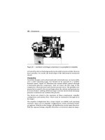
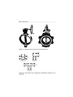
Figure 21.1 is a simplified diagram of a typical centrifugal pump that shows
the relative locations of the pump suction, impeller, volute, and discharge.
The pump casing guides the liquid from the suction connection to the cen-
ter, or eye, of the impeller. The vanes of the rotating impeller impart a
radial and rotary motion to the liquid, forcing it to the outer periphery of
the pump casing, where it is collected in the outer part of the pump casing
called the volute.
The volute is a region that expands in cross-sectional areas as it wraps around
the pump casing. The purpose of the volute is to collect the liquid discharged
Discharge
Impeller eye
Suction
Volute
Impeller
Figure 21.1 Centrifugal pump
396 Pumps
Sin
g
le Double
Figure 21.2 Single and double volute
from the periphery of the impeller at high velocity and gradually cause a
reduction in fluid velocity by increasing the flow area. This converts the
velocity head to static pressure. The fluid is then discharged from the pump
through the discharge connection. Figure 21.2 illustrates the two types of
volutes.
Centrifugal pumps can also be constructed in a manner that results in
two distinct volutes, each receiving the liquid that is discharged from a
180 degrees region of the impeller at any given time. Pumps of this type are
called double volute pumps. In some applications the double volute mini-
mizes radial forces imparted to the shaft and bearings due to imbalances in
the pressure around the impeller.
Characteristics Curve
For a given centrifugal pump operating at a constant speed, the flow rate
through the pump is dependent upon the differential pressure or head
developed by the pump. The lower the pump head, the higher the flow
rate. A vendor manual for a specific pump usually contains a curve of pump
flow rate versus pump head called a pump characteristic curve. After a pump
is installed in a system, it is usually tested to ensure that the flow rate and
head of the pump are within the required specifications. A typical centrifugal
pump characteristic curve is shown in Figure 21.3.
There are several terms associated with the pump characteristic curve that
must be defined. Shutoff head is the maximum head that can be developed
Pumps 397
Shutoff head
Pump head
Pump
runout
Flow rate
Figure 21.3 Centrifugal pump character istics curve
by a centrifugal pump operating at a set speed. Pump run-out is the point
where a centrifugal pump can develop the maximum flow without damaging
the pump. Centrifugal pumps must be designed to be protected from the
conditions of pump run-out or operating at shutoff head.
Protection
A centrifugal pump is deadheaded when it is operated with a closed dis-
charge valve or against a seated check valve. If the discharge valve is closed
and there is no other flow path available to the pump, the impeller will
churn the same volume of water as it rotates in the pump casing. This will
increase the temperature of the liquid in the pump casing to the point that
it will flash to vapor. If the pump is run in this condition for a significant
amount of time, it will become damaged.
When a centrifugal pump is installed in a system in such a way that it may
be subjected to periodic shutoff head conditions, it is necessary to provide
some means of pump protection. One method for protecting the pump
from running deadheaded is to provide a recirculation line from the pump
discharge line upstream of the discharge valve, back to the pump’s supply
source. The recirculation line should be sized to allow enough flow through
the pump to prevent overheating and damage to the pump. Protection may
also be accomplished by use of an automatic flow control device.
Centrifugal pumps must also be protected from runout. One method for
ensuring that there is always adequate flow resistance at the pump discharge
398 Pumps
to prevent excessive flow through the pump is to place an orifice or a throttle
valve immediately downstream of the pump discharge.
Gas Binding
Gas binding of a centrifugal pump is a condition in which the pump casing
is filled with gases or vapors to the point where the impeller is no longer
able to contact enough fluid to function correctly. The impeller spins in the
gas bubble but is unable to force liquid through the pump.
Centrifugal pumps are designed so that their pump casings are completely
filled with liquid during pump operation. Most centrifugal pumps can still
operate when a small amount of gas accumulates in the pump casing, but
pumps in systems containing dissolved gases that are not designed to be
self-venting should be periodically vented manually to ensure that gases do
not build up in the pump casing.
Priming
Most centrifugal pumps are not self-priming. In other words, the pump
casing must be filled with liquid before the pump is started, or the pump
will not be able to function. If the pump casing becomes filled with vapors
or gases, the pump impeller becomes gas-bound and incapable of pumping.
To ensure that a centrifugal pump remains primed and does not become
gas-bound, most centrifugal pumps are located below the level of the source
from which the pump is to take its suction. The same effect can be gained by
supplying liquid to the pump suction under pressure supplied by another
pump placed in the suction line.
Classification by Flow
Centrifugal pumps can be classified based on the manner in which fluid
flows through the pump. The manner in which fluid flows through the
pump is determined by the design of the pump casing and the impeller.
The three types of flow through a centrifugal pump are radial flow, axial
flow, and mixed flow.
Radial Flow
In a radial flow pump, the liquid enters at the center of the impeller and
is directed out along the impeller blades in a direction at right angles to
Pumps 399
Volute
Volute
Impelle
r
Figure 21.4 Radial flow centrifugal pump
Impeller
Figure 21.5 Typical axial flow centrifugal pump
the pump shaft. The impeller of a typical radial flow pump and the flow is
illustrated in Figure 21.4.
Axial Flow
In an axial flow pump, the impeller pushes the liquid in a direction parallel
to the pump shaft. Axial flow pumps are sometimes called propeller pumps
because they operate essentially the same as the propeller of a boat. The
impeller of a typical axial flow pump and the flow through a radial flow
pump are shown in Figure 21.5.
400 Pumps
Impeller
Volute casing
Volute
Figure 21.6 Typical mixed flow pump
Mixed Flow
Mixed flow pumps borrow characteristics from both radial flow and axial
flow pumps. As liquid flows through the impeller of a mixed flow pump,
the impeller blades push the liquid out away from the pump shaft and to the
pump suction at an angle greater than 90 degrees. The impeller of a typical
mixed flow pump and the flow through a mixed flow pump are shown in
Figure 21.6.
Multistage Pumps
A centrifugal pump with a single impeller that can develop a differential
pressure of more than 150 psid between the suction and the discharge is
difficult and costly to design and construct. A more economical approach
to developing high pressures with a single centrifugal pump is to include
multiple impellers on a common shaft within the same pump casing.
Internal channels in the pump casing route the discharge of one impeller to
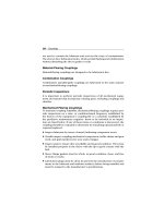
the suction of another impeller. Figure 21.7 shows a diagram of the arrange-
ment of the impellers of a four-stage pump. The water enters the pump from
the top left and passes through each of the four impellers, going from left
to right. The water goes from the volute surrounding the discharge of one
impeller to the suction of the next impeller.
A pump stage is defined as that portion of a centrifugal pump consisting
of one impeller and its associated components. Most centrifugal pumps are
single-stage pumps, containing only one impeller. A pump containing seven
impellers within a single casing would be referred to as a seven-stage pump,
or generally as a multistage pump.
Pumps 401
Figure 21.7 Multistage centrifugal pump
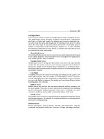
Components
Centrifugal pumps vary in design and construction from simple pumps with
relatively few parts to extremely complicated pumps with hundreds of indi-
vidual parts. Some of the most common components found in centrifugal
pumps are wearing rings, stuffing boxes, packing, and lantern rings. These
components are shown in Figure 21.8 and are described on the following
pages.
Impellers
Impellers of pumps are classified based on the number of points at which the
liquid can enter the impeller and also on the amount of webbing between
the impeller blades.
Impellers can be either single-suction or double-suction. A single-suction
impeller allows liquid to enter the center of the blades from only one
direction. A double-suction impeller allows liquid to enter the center of
the impeller blades from both sides simultaneously. Figure 21.9 shows
simplified diagrams of single- and double-suction impellers.
Impellers can be open, semi-open, or enclosed. The open impeller consists
only of blades attached to a hub. The semi-open impeller is constructed
with a circular plate (the web) attached to one side of the blade. The
enclosed impeller has circular plates attached to both sides of the blades.
402 Pumps
Pump casing
Volute
Volute
Inlet
Packing
Lantern
ring
Impeller
Impeller
wearing ring
Pump casing
wearing ring
Stuffing box
Stuffing
box gland
Pump
shaft
Figure 21.8 Components of a centrifugal pump
Suction
eye
Suction
eye
Suction
eye
Single-suction
Single-suction
Casing
Double-suction
Double-suction
Impeller
Figure 21.9 Single-suction and double-suction impellers
Enclosed impellers are also referred to as shrouded impellers. Figure 21.10
illustrates examples of open, semi-open, and enclosed impellers.
The impeller sometimes contains balancing holes that connect the space
around the hub to the suction side of the impeller. The balancing holes
have a total cross-sectional area that is considerably greater than the
Pumps 403
Figure 21.10 Open, semi-open, and enclosed impellers
cross-sectional area of the annular space between the wearing ring and the
hub. The result is suction pressure on both sides of the impeller hub, which
maintains a hydraulic balance of axial thrust.
Diffuser
Some centrifugal pumps contain diffusers. A diffuser is a set of stationary
vanes that surround the impeller. The purpose of the diffuser is to increase
the efficiency of the centrifugal pump by allowing a more gradual expansion
and less turbulent area for the liquid to reduce in velocity. The diffuser vanes
are designed in a manner that the liquid exiting the impeller will encounter
an ever increasing flow area as it passes through the diffuser. This increase
in flow area causes a reduction in flow velocity, converting kinetic energy
into flow energy. The increase in flow energy can be observed as an increase
in the pressure of an incompressible fluid. Figure 21.11 shows a centrifugal
pump diffuser.
Wearing Rings
Centrifugal pumps contain rotating impellers within stationary pump
casings. To allow the impeller to rotate freely within the pump casing, a
small clearance is maintained between the impeller and the pump casing.
To maximize the efficiency of a centrifugal pump, it is necessary to minimize
the amount of liquid leaking through this clearance from the high pressure
side or discharge side of the pump back to the low pressure or suction
side.
It is unavoidable that some wear will occur at the point where the impeller
and the pump casing nearly come into contact. This wear is due to the
404 Pumps
Rotating impeller
Stationary
difusser vanes
Figure 21.11 Centrifugal pump diffuser
erosion caused by liquid leaking through this tight clearance and other
causes. Eventually, the leakage could become unacceptably large and
maintenance would be required on the pump.
To minimize the cost of pump maintenance, many centrifugal pumps are
designed with wearing rings. Wearing rings are replaceable rings that are
attached to the impeller and/or the pump casing to allow a small running
clearance between the impeller and pump casing without causing wear of
the actual impeller or pump casing material.
Stuffing Box
In almost all centrifugal pumps, the rotating shaft that drives the impeller
penetrates the pressure boundary of the pump casing. It is important that
the pump is designed properly to control the amount of liquid that leaks
along the shaft at the point that the shaft penetrates the pump casing. Factors
considered when choosing a method include the pressure and temperature
of the fluid being pumped, the size of the pump, and the chemical and
physical characteristics of the fluid being pumped.
One of the simplest types of shaft seal is the stuffing box. The stuffing box
is a cylindrical space in the pump casing surrounding the shaft. Rings of
packing material are placed in this space. Packing is material in the form of
rings or strands that is placed in the stuffing box to form a seal to control
the rate of leakage along the shaft. The packing rings are held in place by
Pumps 405
a gland. The gland is, in turn, held in place by studs with adjusting nuts.
As the adjusting nuts are tightened, they move the gland in and compress
the packing. This axial compression causes the packing to expand radially,
forming a tight seal between the rotating shaft and the inside wall of the
stuffing box.
The high-speed rotation of the shaft generates a significant amount of heat as
it rubs against the packing rings. If no lubrication and cooling are provided
to the packing, the temperature of the packing increases to the point where
damage occurs to the packing, the pump shaft, and possibly the nearby
pump bearing. Stuffing boxes are normally designed to allow a small amount
of controlled leakage along the shaft to provide lubrication and cooling to
the packing. Tightening and loosening the packing gland can adjust the
leakage rate.
Lantern Ring
It is not always possible to use a standard stuffing box to seal the shaft
of a centrifugal pump. The pump suction may be under a vacuum so that
outward leakage is impossible, or the fluid may be too hot to provide ade-
quate cooling of the packing. These conditions require a modification to
the standard stuffing box.
One method of adequately cooling the packing under these conditions is to
include a lantern ring. A lantern ring is a perforated hollow ring located near
the center of the packing box that receives relatively cool, clean liquid from
either the discharge of the pump or from an external source and distributes
the liquid uniformly around the shaft to provide lubrication and cooling. The
fluid entering the lantern ring can cool the shaft and packing, lubricate the
packing, or seal the joint between the shaft and packing against leakage of
air into the pump in the event the pump suction pressure is less than that
of the atmosphere.
Mechanical Seals
In some situations, packing material is not adequate for sealing the shaft.
One common alternative method for sealing the shaft is with mechanical
seals. Mechanical seals consist of two basic parts, a rotating element attached
to the pump shaft and a stationary element attached to the pump casing.
Each of these elements has a highly polished sealing surface. The polished
faces of the rotating and stationary elements come into contact with each
other to form a seal that prevents leakage along the shaft.
406 Pumps
Summary
The important information is summarized below.
●
Centrifugal pumps contain components with distinct purposes. The
impeller contains rotating vanes that impart a radial and rotary motion to
the liquid.
●
The volute collects the liquid discharged from the impeller at high velocity
and gradually causes a reduction in fluid velocity by increasing the flow
area, converting the velocity head to a static head.
●
A diffuser increases the efficiency of a centrifugal pump by allowing a
more gradual expansion and less turbulent area for the liquid to slow as
the flow area expands.
●
Packing material provides a seal in the area where the pump shaft
penetrates the pump casing.
●
Wearing rings are replaceable rings that are attached to the impeller and/or
the pump casing to allow a small running clearance between the impeller
and pump casing without causing wear of the actual impeller or pump
casing material.
●
The lantern ring is inserted between rings of packing in the stuffing
box to receive relatively cool, clean liquid and distribute the liquid
uniformly around the shaft to provide lubrication and cooling to the
packing.
●
There are three indications that a centrifugal pump is cavitating:
1 Noise
2 Fluctuating discharge pressure and flow
3 Fluctuating pump motor current
●
Steps that can be taken to stop pump cavitation include:
1 Increasing the pressure at the suction of the pump
2 Reducing the temperature of the liquid being pumped
3 Reducing head losses in the pump suction piping
Pumps 407
4 Reducing the flow rate through the pump
5 Reducing the speed of the pump impeller
●
Three effects of pump cavitation are:
1 Degrading pump performance
2 Excessive pump vibration
3 Damage to pump impeller, bearing, wearing rings, and seals
●
To avoid pump cavitation, the net positive suction head available must be
greater than the net positive suction head required.
●
Net positive suction head available is the difference between the pump
suction pressure and the saturation pressure for the liquid being
pumped.
●
Cavitation is the process of the formation and subsequent collapse of
vapor bubbles in a pump.
●
Gas binding of a centrifugal pump is a condition where the pump casing
is filled with gases or vapors to the point where the impeller is no longer
able to contact enough fluid to function correctly.
●
Shutoff head is the maximum head that can be developed by a centrifugal
pump operating at a set speed.
●
Pump run-out is the maximum flow that can be developed by a centrifugal
pump without damaging the pump.
●
The greater the head against which a centrifugal pump operates, the
lower the flow rate through the pump. The relationship between pump
flow rate and head is illustrated by the characteristic curve for the
pump.
●
Centrifugal pumps are protected from deadheading by providing a recir-
culation from the pump discharge back to the supply source of the
pump.
●
Centrifugal pumps are protected from run-out by placing an orifice or
throttle valve immediately downstream of the pump discharge.
408 Pumps
Positive Displacement Pumps
A positive displacement pump is one in which a definite volume of liquid is
delivered for each cycle of pump operation. This volume is constant regard-
less of the resistance to flow offered by the system the pump is in, provided
the capacity of the power unit driving the pump is not exceeded. The posi-
tive displacement pump delivers liquid in separate volumes with no delivery
in between, although a pump having several chambers may have an overlap-
ping delivery among individual chambers, which minimizes this effect. The
positive displacement pump differs from other types of pumps that deliver
a continuous even flow for any given pump speed and discharge.
Positive displacement pumps can be grouped into three basic categories
based on their design and operation: reciprocating pumps, rotary pumps,
and diaphragm pumps.
Principles of Operation
All positive displacement pumps operate on the same basic principle. This
principle can be most easily demonstrated by considering a reciprocating
positive displacement pump consisting of a single reciprocating piston in a
cylinder with a single suction port and a single discharge port, as shown in
Figure 21.12.
Reservoir Reservoir
Suction Suction
Discharge
Discharge
Discharge strokeSuction stroke
Figure 21.12 Reciprocating positive displacement pump operation