Industrial Machinery Repair Part Episode 2 Part 1 pptx
Bạn đang xem bản rút gọn của tài liệu. Xem và tải ngay bản đầy đủ của tài liệu tại đây (213 KB, 25 trang )
234 Couplings
are used to contain the lubricant and seal out the entry of contaminants.
The sleeves have lubrication holes, which permit flushing and relubrication
without disturbing the sleeve gasket or seals.
Material-Flexing Couplings
Material-flexing couplings are designed to be lubrication free.
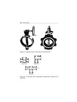
Combination Couplings
Combination (metallic-grid) couplings are lubricated in the same manner
as mechanical-flexing couplings.
Periodic Inspections
It is important to perform periodic inspections of all mechanical equip-
ment and systems that incorporate rotating parts, including couplings and
clutches.
Mechanical-Flexing Couplings
To maintain coupling reliability, mechanical-flexing couplings require peri-
odic inspections on a time- or condition-based frequency established by
the history of the equipment’s coupling life or a schedule established by
the predictive maintenance engineer. Items to be included in an inspec-
tion are listed below. If any of these items or conditions is discovered, the
coupling should be evaluated to determine its remaining operational life or
repaired/replaced.
●
Inspect lubricant for traces of metal (indicating component wear).
●
Visually inspect coupling mechanical components (roller chains and gear
teeth, and grid members) for wear and/or fatigue.
●
Inspect seals to ensure they are pliable and in good condition. They must
be installed properly in the sleeve with the lip in good contact with the
hub.
●
Sleeve flange gaskets must be whole, in good condition, clean, and free
of nicks or cracks.
●
Lubrication plugs must be clean (to prevent the introduction of contam-
inants to the lubricant and machine surfaces) before being installed and
must be torqued to the manufacturer’s specifications.
Couplings 235
●
Setscrews and retainers must be in place and tightened to manufacturer’s
specifications.
●
Inspect shaft hubs, keyways, and keys for cracks, breaks, and physical
damage.
●
Under operating conditions, perform thermographic scans to determine
temperature differences on the coupling (indicates misalignment and/or
uneven mechanical forces).
Material-Flexing Couplings
Although designed to be lubrication-free, material-flexing couplings also
require periodic inspection and maintenance. This is necessary to ensure
that the coupling components are within acceptable specification limits.
Periodic inspections for the following conditions are required to main-
tain coupling reliability. If any of these conditions are found, the cou-
pling should be evaluated to determine its remaining operational life or
repaired/replaced.
●
Inspect flexing element for signs of wear or fatigue (cracks, element dust,
or particles).
●
Setscrews and retainers must be in place and tightened to manufacturer’s
specifications.
●
Inspect shaft hubs, keyways, and keys for cracks, breaks, and physical
damage.
●
Under operating conditions, perform thermographic scans for tempera-
ture differences on the coupling, which indicates misalignment and/or
uneven mechanical forces.
Combination Couplings
Mechanical components (e.g., grid members) should be visually inspected
for wear and/or fatigue. In addition to the items for mechanical-flexing cou-
plings, the grid members on metallic-grid couplings should be replaced if
any signs of wear are observed.
Rigid Couplings
The mechanical components of rigid couplings (e.g., hubs, bolts, compres-
sion sleeves and halves, keyways, and keys) should be visually inspected
236 Couplings
for cracks, breaks, physical damage, wear, and/or fatigue. Any component
having any of these conditions should be replaced.
Keys, Keyways, and Keyseats
A key is a piece of material, usually metal, placed in machined slots or
grooves cut into two axially oriented parts in order to mechanically lock
them together. For example, keys are used in making the coupling con-
nection between the shaft of a driver and a hub or flange on that shaft.
Any rotating element whose shaft incorporates such a keyed connection is
referred to as a keyed-shaft rotor. Keys provide a positive means for trans-
mitting torque between the shaft and coupling hub when a key is properly
fitted in the axial groove.
The groove into which a key is fitted is referred to as a keyseat when referring
to shafts, and a keyway when referring to hubs. Keyseating is the actual
machine operation of producing keyseats. Keyways are normally made on a
keys eater or by a broach. Keyseats are normally made with a rotary or end
mill cutter.
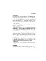
Figure 11.15 is an example of a keyed shaft that shows the key size versus the
shaft diameter. Because of standardization and interchangeability, keys are
generally proportioned with relation to shaft diameter instead of torsional
load.
The effective key length, “L” is that portion of key having full bearing on
hub and shaft. Note that the curved portion of the keyseat made with a
Top view
End mill
cutter
Top view
L
L
Rotary
cutter
Figure 11.15 Keyed shaft: key size versus shaft diameter
Couplings 237
TOP VIEWS
Square ends
Square and round
Rounded ends
Gib head taper
Plain taper
SIDE VIEWS
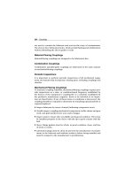
Figure 11.16 Key shapes
rotary cutter does not provide full key bearing, so “L” does not include this
distance. The use of an end mill cutter results in a square-ended keyseat.
Figure 11.16 shows various key shapes: square ends, one square end and
one round end, rounded ends, plain taper, and gib head taper. The majority
of keys are square in cross section, which are preferred through 4
1
2
" diame-
ter shafts. For bores over 4
1
2
" and thin wall sections of hubs, the rectangular
(flat) key is used.
The ends are either square, rounded or gib-head. The gib-head is usually
used with taper keys. If special considerations dictate the use of a keyway
in the hub shallower than the preferred square key, it is recommended that
the standard rectangular (flat) key be used.
Hub bores are usually straight, although for some special applications taper
bores are sometimes specified. For smaller diameters, bores are designed
for clearance fits, and a setscrew is used over the key. The major advantage
of a clearance fit is that hubs can be easily assembled and disassembled.
For larger diameters, the bores are designed for interference fits without
setscrews. For rapid-reversing applications, interference fits are required.
The sections to follow discuss determining keyway depth and width, key-
way manufacturing tolerances, key stress calculations, and shaft stress
calculations.
Determining Keyway Depth and Width
The formula given below, along with Figure 11.17, Table 11.2 (square keys),
and Table 11.3 (flat keys), illustrates how the depth and width of standard
238 Couplings
Shafts Hubs
H/2
S = DϪYϪH
2
T = DϪYϩHϩ
C
H /2
W
D
D
Y
Y
T
S
2
Figure 11.17 Shaft and hub dimensions
square and flat keys and keyways for shafts and hubs are determined.
Y =
D −
D
2
− W
2
2
Where:
C = Allowance or clearance for key, inches
D = Nominal shaft or bore diameter, inches
H = Nominal key height, inches
W = Nominal key width, inches
Y = Chordal height, inches
Note: Tables 11.2 and 11.3 shown below are prepared for manufacturing
use. Dimensions given are for standard shafts and keyways.
Keyway Manufacturing Tolerances
Keyway manufacturing tolerances (illustrated in Figure 11.18) are referred
to as offset (centrality) and lead (cross axis). Offset or centrality is referred
Couplings 239
Table 11.2 Standard square keys and keyways (inches)*
Keyways
Diameter of holes (inclusive) Width Depth Key stock
5/16 to 7/16 3/32 3/64 3/32 × 3/32
1/2 to 9/16 1/8 1/16 1/8 × 1/8
5/8 to 7/8 3/16 3/32 3/16 × 3/16
1 5/16 to 11/4 1/4 1/8 1/4 × 1/4
1 5/16 to 13/8 5/16 5/32 5/16 × 5/16
1 7/16 to 13/4 3/8 3/16 3/8 × 3/8
1 13/16 to 21/4 1/2 1/4 1/2 × 1/2
2 5/16 to 23/4 5/8 5/16 5/8 × 5/8
2 13/16 to 31/4 3/4 3/8 3/4 × 3/4
3 5/16 to 33/4 7/8 7/16 7/8 × 7/8
3 13/16 to 4 1/2 1 1/2 1 × 1
Source: The Falk Corporation
*Square keys are normally used through shaft diameter 4
1
2
"; larger shafts normally
use flat keys.
to as dimension “N”; lead or cross axis is referred to as dimension “J.” Both
must be kept within permissible tolerances, usually 0.002 inches.
Key Stress Calculations
Calculations for shear and compressive key stresses are based on the
following assumptions:
1 The force acts at the radius of the shaft.
2 The force is uniformly distributed along the key length.
3 None of the tangential load is carried by the frictional fit between shaft
and bore.
The shear and compressive stresses in a key are calculated using the
following equations (see Figure 11.19):
Ss =
2T
(d)x(w )x(L)
Sc =
2T
(d)x(h
1
)x(L)
240 Couplings
Table 11.3 Standard flat keys and keyways (inches)
Keyways
Diameter of holes (inclusive) Width Depth Key stock
1/2 to 9/16" 1/8 3/64 1/8 × 1/32
5/8 to 7/8" 3/16 1/16 3/16 × 1/8
1 5/16 to 1 1/4" 1/4 3/32 1/4 × 3/16
1 5/16 to 1 3/8" 5/16 1/8 5/16 × 1/4
1 7/16 to 1 3/4" 3/8 1/8 3/8 × 1/4
1 13/16 to 2 1/4" 1/2 3/16 1/2 × 3/8
2 5/16 to 2 3/4" 5/8 7/32 5/8 × 7/16
2 13/16 to 3 1/4" 3/4 1/4 3/4 × 1/2
3 5/16 to 33/4" 7/8 5/16 7/8 × 5/8
3 13/16 to 4 1/2" 1 3/8 1 × 3/4
4 9/16 to 5 1/2" 1 1/4 7/16 1 1/4 × 7/8
5 9/16 to 6 1/2" 1 1/2 1/2 1 1/2 × 1
6 9/16 to 7 1/2" 1 3/4 5/8 1 3/4 × 11/4
79/16to9" 2 3/4 2× 11/2
9 1/16 to 11" 2 1/2 7/8 2 1/2 × 13/4
11 1/16 to 13" 3 1 3 × 2
13 1/16 to 15" 3 1/2 1 1/4 3 1/2 × 21/2
15 1/16 to 18" 4 1 1/2 4 × 3
18 1/16 to 22" 5 1 3/4 5 × 31/2
22 1/16 to 26" 6 4
26 1/16 to 30" 7 5
Source: The Falk Corporation
Where:
d = Shaft diameter, inches (use average diameter for taper shafts)
h
1
= Height of key in the shaft or hub that bears against the keyway,
inches. Should equal h
2
for square keys. For designs where
unequal portions of the key are in the hub or shaft, h
1
is the
minimum portion.
Couplings 241
Offset or centrality
Shaft
Bore
Keyseat
N
C
C
C
C
Lead or cross axis
(a)
(b)
Shaft
Keyseat
Keyseat
Bor
e
Lead
Lead
C
C
C
C
Figure 11.18 Manufacturing tolerances: offset and lead
hp = Power, horsepower
L = Effective length of key, inches
rpm = Revolutions per minute
Ss = Shear stress, psi
Sc = Compressive stress, psi
T = Shaft torque, lb-in or
hp × 63000
rpm
w = Key width, inches
242 Couplings
d Shaft diameter
Clearance
h
2
h
1
W
H
Figure 11.19 Measurements used in calculating shear and compressive
key stress
Table 11.4 Allowable stresses for AISI 1018 and AISI 1045
Allowable stresses - psi
Heat
Material treatment Shear Compressive
AISI 1018 None 7,500 15,000
AISI 1045 255–300 Bhn 15,000 30,000
Source: The Falk Corporation
Key material is usually AISI 1018 or AISI 1045. Table 11.4 provides the
allowable stresses for these materials.
Example: Select a key for the following conditions: 300 hp at 600 rpm;
3" diameter shaft,
3
4
" ×
3
4
" key, 4" key engagement length.
T = Torque =
hp × 63,000
rpm
=
300 × 63,000
600
= 31,500 in-lbs
Ss =
2T
d × w × L
=
2 × 31,500
3 × 3/4 × 4
= 7,000 psi
Sc =
2T
d × h
1
× L
=
2 × 31,500
3 × 3/8 × 4
= 14,000 psi
The AISI 1018 key can be used since it is within allowable stresses listed in
Table 11.4 (allowable Ss = 7,500; allowable Sc = 15,000).
Couplings 243
Note: If shaft had been 2-
3
4
" diameter (4" hub), the key would be
5
8
" ×
5
8
",
Ss = 9,200 psi, Sc = 18,400 psi, and a heat-treated key of AISI 1045 would
have been required (allowable Ss = 15,000, allowable Sc = 30,000).
Shaft Stress Calculations
Torsional stresses are developed when power is transmitted through shafts.
In addition, the tooth loads of gears mounted on shafts create bending stre-
sses. Shaft design, therefore, is based on safe limits of torsion and bending.
To determine minimum shaft diameter in inches:
Minimum shaft diameter =
3
hp × 321000
rpm × Allowable stress
Example:
hp = 300
rpm = 30
Material = 225 Brinell
From Figure 11.20 at 225 Brinell, allowable torsion = 8,000 psi
Minimum shaft diameter =
3
300 × 321000
30 × 8000
=
3
√
402 = 7. 38 inches
From Table 11.5, note that the cube of 7
1
4
" is 381, which is too small (i.e.,
<402) for this example. The cube of 7
1
2
" is 422, which is large enough.
To determine shaft stress, psi:
Shaft stress =
hp × 321,000
rpm × d
3
Example: Given 7
1
2
" shaft for 300 hp at 30 rpm
Shaft stress =
300 × 321,000
30 × (7 − 1/2)
3
= 7,600 psi
Note: The 7
1
4
" diameter shaft would be stressed to 8420 psi.
244 Couplings
Allowable tensile strength (psi)
Brinell hardness
Tensile strength, 1000 psi (Approx.)
24000
20000
16000
12000
8000
4000
160
80 100 120 140 160 180 200 220
200 240 280 320 360 400 440
Bending
Bending
Torsion
Torsion
Bending
Torsion
Figure 11.20 Allowable stress as a function of Brinell hardness
Table 11.5 Shaft diameters (inches) and their cubes (cubic inches)
DD
3
DD
3
DD
3
1 1.00 5 125.0 9 729
1 1/4 1.95 5 1/4 145 9 1/2 857
1 1/2 3.38 5 1/2 166.4 10 1000
1 3/4 5.36 5 3/4 190.1 10 1/2 1157
2 8.00 6 216 11 1331
2 1/4 11.39 6 1/4 244 11 1/2 1520
2 1/2 15.63 6 1/2 275 12 1728
2 3/4 20.80 6 3/4 308 12 1/2 1953
3 27.00 7 343 13 2197
3 1/4 34.33 7 1/4 381 14 2744
3 1/2 42.88 7 1/2 422 15 3375
3 3/4 52.73 7 3/4 465 16 4096
4 64.00 8 512 17 4913
4 1/4 76.77 8 1/4 562 18 5832
4 1/2 91.13 8 1/2 614 19 6859
4 3/4 107.2 8 3/4 670 20 8000
Source: The Falk Corporation
12 Dust Collectors
The basic operations performed by dust-collection devices are: (1) separat-
ing particles from the gas stream by deposition on a collection surface,
(2) retaining the deposited particles on the surface until removal, and
(3) removing the deposit from the surface for recovery or disposal.
The separation step requires: (1) application of a force that produces a
differential motion of the particles relative to the gas, and (2) sufficient gas-
retention time for the particles to migrate to the collecting surface. Most
dust-collections systems are comprised of a pneumatic-conveying system
and some device that separates suspended particulate matter from the con-
veyed air stream. The more common systems use either filter media (e.g.,
fabric bags) or cyclonic separators to separate the particulate matter from
air.
Baghouses
Fabric-filter systems, commonly called bag-filter or baghouse systems, are
dust-collection systems in which dust-laden air is passed through a bag-type
filter. The bag collects the dust in layers on its surface, and the dust layer
itself effectively becomes the filter medium. Because the bag’s pores are
usually much larger than those of the dust-particle layer that forms, the
initial efficiency is very low. However, it improves once an adequate dust
layer forms. Therefore, the potential for dust penetration of the filter media
is extremely low except during the initial period after startup, bag change,
or during the fabric-cleaning, or blow-down, cycle.
The principle mechanisms of disposition in dust collectors are: (1) grav-
itational deposition, (2) flow-line interception, (3) inertial deposition,
(4) diffusion deposition, and (5) electrostatic deposition. During the ini-
tial operating period, particle deposition takes place mainly by inertial
and flow-line interception, diffusion, and gravity. Once the dust layer
has been fully established, sieving is probably the dominant deposition
mechanism.
246 Dust Collectors
Configuration
A baghouse system consists of the following: a pneumatic-conveyor system,
filter media, a back-flush cleaning system, and a fan or blower to provide
airflow.
Pneumatic Conveyor
The primary mechanism for conveying dust-laden air to a central collection
point is a system of pipes or ductwork that functions as a pneumatic con-
veyor. This system gathers dust-laden air from various sources within the
plant and conveys it to the dust-collection system.
Dust-Collection System
Design and configuration of the dust-collection system varies with the ven-
dor and the specific application. Generally, a system consists of either a
single large hopper-like vessel or a series of hoppers with a fan or blower
affixed to the discharge manifold. Inside the vessel is an inlet manifold that
directs the incoming air or gas to the dirty side of the filter media or bag. A
plenum, or divider plate, separates the dirty and clean sides of the vessel.
Filter media, usually long cylindrical tubes or bags, are attached to the
plenum. Depending on the design, the dust-laden air or gas may flow into
the cylindrical filter bag and exit to the clean side, or it may flow through
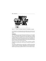
the bag from its outside and exit through the tube’s opening. Figure 12.1
illustrates a typical baghouse configuration.
Fabric-filter designs fall into three types, depending on the method of
cleaning used: (1) shaker-cleaned, (2) reverse-flow-cleaned, and (3) reverse-
pulse-cleaned.
Shaker-Cleaned Filter
The open lower ends of shaker-cleaned filter bags are fastened over open-
ings in the tube sheet that separate the lower, dirty-gas inlet chamber from
the upper clean-gas chamber. The bags are suspended from supports, which
are connected to a shaking device.
The dirty gas flows upward into the filter bag, and the dust collects on the
inside surface. When the pressure drop rises to a predetermined upper
limit due to dust accumulation, the gas flow is stopped and the shaker is
operated. This process dislodges the dust, which falls into a hopper located
below the tube sheet.
Dust Collectors 247
Bag support
and shaking
mechanism
Clean gas side
Dirty gas side
Dust discharge
Figure 12.1 A typical baghouse
For continuous operation, the filter must be constructed with multiple
compartments. This is necessary so that individual compartments can
be sequentially taken offline for cleaning while the other compartments
continue to operate.
Ordinary shaker-cleaned filters may be cleaned every fifteen minutes to eight
hours, depending on the service conditions. A manometer connected across
the filter is used to determine the pressure drop, which indicates when
the filter should be shaken. Fully automatic filters may be shaken every
two minutes, but bag maintenance is greatly reduced if the time between
shakings can be increased to 15 to 20 minutes.
The determining factor in the frequency of cleaning is the pressure drop.
A differential-pressure switch can serve as the actuator in automatic cleaning
applications. Cyclone precleaners are sometimes used to reduce the dust
load on the filter or to remove large particles before they enter the bag.
It is essential to stop the gas flow through the filter during shaking in order
for the dust to fall off. With very fine dust, it may be necessary to equalize
248 Dust Collectors
the pressure across the cloth. In practice, this can be accomplished without
interrupting continuous operation by removing one section from service at
a time. With automatic filters, this operation involves closing the dirty-gas
inlet dampers, shaking the filter units either pneumatically or mechanically,
and reopening the dampers. In some cases, a reverse flow of clean gas
through the filter is used to augment the shaker-cleaning process.
The gas entering the filter must be kept above its dew point to avoid water-
vapor condensation on the bags, which will cause plugging. However,
fabric filters have been used successfully in steam atmospheres, such as
those encountered in vacuum dryers. In these applications, the housing is
generally steam-cased.
Reverse-Flow-Cleaned Filter
Reverse-flow-cleaned filters are similar to the shaker-cleaned design, except
the shaker mechanism is eliminated. As with shaker-cleaned filters, com-
partments are taken offline sequentially for cleaning. The primary use of
reverse-flow cleaning is in units using fiberglass-fabric bags at temperatures
above 150
◦
C (300
◦
F).
After the dirty-gas flow is stopped, a fan forces clean gas through the bags
from the clean-gas side. The superficial velocity of the gas through the bag is
generally 1.5 to 2.0 feet per minute, or about the same velocity as the dirty-
gas inlet flow. This flow of clean gas partially collapses the bag and dislodges
the collected dust, which falls to the hopper. Rings are usually sewn into
the bags at intervals along their length to prevent complete collapse, which
would obstruct the fall of the dislodged dust.
Reverse-Pulse-Cleaned Filter
In the reverse-pulse-cleaned filter, the bag forms a sleeve drawn over a cylin-
drical wire cage, which supports the fabric on the clean-gas side (i.e., inside)
of the bag. The dust collects on the outside of the bag.
A venturi nozzle is located in the clean-gas outlet from each bag, which is
used for cleaning. A jet of high-velocity air is directed through the venturi
nozzle and into the bag, which induces clean gas to pass through the fabric
to the dirty side. The high-velocity jet is released in a short pulse, usually
about 100 milliseconds, from a compressed air line by a solenoid-controlled
valve. The pulse of air and clean gas expand the bag and dislodge the col-
lected dust. Rows of bags are cleaned in a timed sequence by programmed
operation of the solenoid valves. The pressure of the pulse must be sufficient
to dislodge the dust without cessation of gas flow through the baghouse.
Dust Collectors 249
It is common practice to clean the bags online without stopping the flow of
dirty gas into the filter. Therefore, reverse-pulse bag filters are often built
without multiple compartments. However, investigations have shown that
a large fraction of the dislodged dust redeposits on neighboring bags rather
than falling to the dust hopper.
As a result, there is a growing trend to offline clean reverse-pulse filters by
using bags with multiple compartments. These sections allow the outlet-
gas plenum serving a particular section to be closed off from the clean-gas
exhaust, thereby stopping the flow of inlet gas. On the dirty side of the
tube sheet, the isolated section is separated by partitions from the neigh-
boring sections where filtration continues. Sections of the filter are cleaned
in rotation as with shaker and reverse-flow filters.
Some manufacturers design bags for use with relatively low-pressure air(i.e.,
15 psi) instead of the normal 100 psi air. This allows them to eliminate the
venturi tubes for clean-gas induction. Others have eliminated the separate
jet nozzles located at the individual bags in favor of a single jet to pulse air
into the outlet-gas plenum.
Reverse-pulse filters are typically operated at higher filtration velocities (i.e.,
air-to-cloth ratios) than shaker or reverse-flow designs. Filtration velocities
may range from three to fifteen feet per minute in reverse-pulse applications,
depending on the dust being collected. However, the most the commonly
used range is four to five feet per minute.
The frequency of cleaning depends on the nature and concentration of
the dust. Typical cleaning intervals vary from about two to fifteen minutes.
However, the cleaning action of the pulse is so effective that the dust layer
may be completely removed from the surface of the fabric. Consequently,
the fabric itself must serve as the principal filter medium for a substantial
part of the filtration cycle, which decreases cleaning efficiency. Because of
this, woven fabrics are unsuitable for use in these devices, and felt-type
fabrics are used instead. With felt filters, although the bulk of the dust is still
removed, the fabric provides an adequate level of dust collection until the
dust layer reforms.
Cleaning System
As discussed in the preceding section, filter bags must be periodically
cleaned to prevent excessive buildup of dust and to maintain an accept-
able pressure drop across the filters. Two of the three designs discussed,
250 Dust Collectors
reverse-flow and reverse-pulse, depend on an adequate supply of clean air
or gas to provide this periodic cleaning. Two factors are critical in these
systems: the clean-gas supply and the proper cleaning frequency.
Clean-Gas Supply
Most applications that use the reverse-flow cleaning system use ambient air
as the primary supply of clean gas. A large fan or blower draws ambient air
into the clean side of the filter bags. However, unless inlet filters properly
condition the air, it may contain excessive dirt loads that can affect the bag
life and efficiency of the dust-collection system.
In reverse-pulse applications, most plants rely on plant-air systems as the
source for the high-velocity pulses required for cleaning. In many cases,
however, the plant-air system is not sufficient for this purpose. Although
the pulses required are short (i.e., 100 milliseconds or less), the number
and frequency can deplete the supply. Therefore, care must be taken to
ensure that both sufficient volume and pressure are available to achieve
proper cleaning.
Cleaning Frequency
Proper operation of a baghouse, regardless of design, depends on frequent
cleaning of the filter medium. The system is designed to operate within a spe-
cific range of pressure drops that defines clean and fully loaded filter media.
The cleaning frequency must assure that the maximum recommended
pressure drop is not exceeded.
This can be a real problem for baghouses that rely on automatic timers to
control cleaning frequency. The use of a timing function to control cleaning
frequency is not recommended unless the dust load is known to be consis-
tent. A better approach is to use differential-pressure gauges to physically
measure the pressure drop across the filter medium to trigger the cleaning
process based on preset limits.
Fan or Blower
All baghouse designs use some form of fan, blower, or centrifugal com-
pressor to provide the dirty-air flow required for proper operation. In most
cases, these units are installed on the clean side of the baghouse to draw
the dirty air through the filter media.
Since these units provide the motive power required to transport and col-
lect the dust-laden air, their operating condition is critical to the baghouse
Dust Collectors 251
system. The type and size of air-moving unit varies with the baghouse type
and design. Refer to the O&M manuals, for specific design criteria for these
critical units.
Performance
The primary measure of baghouse-system performance is its ability to con-
sistently remove dust and other particulate matter from the dirty-air stream.
Pressure drop and collection efficiency determine the effectiveness of these
systems.
Pressure Drop
The filtration, or superficial face, velocities used in fabric filters are generally
in the range of one to ten feet per minute, depending on the type of fabric,
fabric supports, and cleaning methods used. In this range, pressure drops
conform to Darcy’s law for streamline flow in porous media, which states
that the pressure drop is directly proportional to the flow rate. The pressure
drop across the fabric media and the dust layer may be expressed by:
p=K
1
V
f
+K
2
ω V
f
Where:
p = pressure drop (inches of water)
V
f
= superficial velocity through filter (feet/minute)
ω = dust loading on filter (lbm/ft
2
)
K
1
= resistance coefficient for conditioned fabric (inches of water/foot/
minute)
K
2
= resistance coefficient for dust layer (inches of water/lbm/foot/
minute)
Conditioned fabric maintains a relatively consistent dust-load deposit fol-
lowing a number of filtration and cleaning cycles. K
1
may be more than 10
times the value of the resistance coefficient for the original clean fabric. If
the depth of the dust layer on the fabric is greater than about
1
16
" (which
corresponds to a fabric dust loading on the order of 0.1 lbm/ft
2
), the pres-
sure drop across the fabric, including the dust in the pores, is usually
negligible relative to that across the dust layer alone.
In practice, K
1
and K
2
are measured directly in filtration experiments. These
values can be corrected for temperature by multiplying by the ratio of the
252 Dust Collectors
gas viscosity at the desired condition to the gas viscosity at the original
experimental condition.
Collection Efficiency
Under controlled conditions (e.g., in the laboratory), the inherent collec-
tion efficiency of fabric filters approaches 100%. In actual operation, it is
determined by several variables, in particular the properties of the dust to be
removed, choice of filter fabric, gas velocity, method of cleaning, and clean-
ing cycle. Inefficiency usually results from bags that are poorly installed,
torn, or stretched from excessive dust loading and excessive pressure
drop.
Installation
Most baghouse systems are provided as complete assemblies by the vendor.
While the unit may require some field assembly, the vendor generally
provides the structural supports, which in most cases are adequate. The
only controllable installation factors that may affect performance are the
foundation and connections to pneumatic conveyors and other supply
systems.
Foundation
The foundation must support the weight of the baghouse. In addition, it
must absorb the vibrations generated by the cleaning system. This is espe-
cially true when using the shaker-cleaning method, which can generate
vibrations that can adversely affect the structural supports, foundation, and
adjacent plant systems.
Connections
Efficiency and effectiveness depend on leak-free connections throughout
the system. Leaks reduce the system’s ability to convey dust-laden air to
the baghouse. One potential source for leaks is improperly installed filter
bags. Because installation varies with the type of bag and baghouse design,
consult the vendor’s O&M manual for specific instructions.
Operating Methods
The guidelines provided in the vendor’s O&M manual should be the primary
reference for proper baghouse operation. Vendor-provided information
Dust Collectors 253
should be used because there are not many common operating guide-
lines among the various configurations. The only general guidelines that
are applicable to most designs are cleaning frequency and inspection and
replacement of filter media.
Cleaning
As previously indicated, most bag-type filters require a precoat of particu-
lates before they can effectively remove airborne contaminants. However,
particles can completely block air flow if the filter material becomes over-
loaded. Therefore, the primary operating criterion is to maintain the
efficiency of the filter media by controlling the cleaning frequency.
Most systems use a time-sequence to control the cleaning frequency. If the
particulate load entering the baghouse is constant, this approach would be
valid. However, the incoming load generally changes constantly. As a result,
the straight time-sequence methodology does not provide the most efficient
mode of operation.
Operators should monitor the differential-pressure gauges that measure the
total pressure drop across the filter media. When the differential pressure
reaches the maximum recommended level (data provided by the vendor),
the operator should override any automatic timer controls and initiate the
cleaning sequence.
Inspecting and Replacing Filter Media
Filter media used in dust-collection systems are prone to damage and abra-
sive wear. Therefore, regular inspection and replacement is needed to
ensure continuous, long-term performance. Any damaged, torn, or improp-
erly sealed bags should be removed and replaced. One of the more common
problems associated with baghouses is improper installation of filter media.
Therefore, it is important to follow the instructions provided by the vendor.
If the filter bags are not properly installed and sealed, overall efficiency and
effectiveness are significantly reduced.
Cyclone Separators
A widely used type of dust-collection equipment is the cyclone separator. A
cyclone is essentially a settling chamber in which gravitational acceleration is
254 Dust Collectors
replaced by centrifugal acceleration. Dust-laden air or gas enters a cylindrical
or conical chamber tangentially at one or more points and leaves through
a central opening. The dust particles, by virtue of their inertia, tend to
move toward the outside separator wall from where they are led into a
receiver. Under common operating conditions, the centrifugal separating
force or acceleration may range from five times gravity in very large diameter,
low-resistance cyclones to 2,500 times gravity in very small, high-resistance
units.
Within the range of their performance capabilities, cyclones are one of the
least expensive dust-collection systems. Their major limitation is that, unless
very small units are used, efficiency is low for particles smaller than five
microns. Although cyclones may be used to collect particles larger than
200 microns, gravity-settling chambers or simple inertial separators are
usually satisfactory and less subject to abrasion.
Configuration
The internal configuration of a cyclone separator is relatively simple.
Figure 12.2 illustrates a typical cross-section of a cyclone separator, which
Clean-gas outlet
Dust shave-off
Shave-off-dust channel
Shave-off-reentry opening
Pattern of coarser
dust mainstream
Dust outlet
Inlet for dust-laden gases
Pattern of dust stream
(principally the finer particles)
following eddy current
Figure 12.2 Flow pattern through a typical cyclone separator
Dust Collectors 255
consists of the following segments:
●
Inlet area that causes the gas to flow tangentially;
●
Cylindrical transition area;
●
Decreasing taper that increases the air velocity as the diameter decreases;
●
Central return tube to direct the dust-free air out the discharge port.
Particulate material is forced to the outside of the tapered segment and
collected in a drop-leg located at the dust outlet. Most cyclones have a
rotor-lock valve affixed to the bottom of the drop-leg. This is a motor-driven
valve that collects the particulate material and discharges it into a disposal
container.
Performance
Performance of a cyclone separator is determined by flow pattern, pressure
drop, and collection efficiency.
Flow Pattern
The path the gas takes in a cyclone is through a double vortex that spirals
the gas downward at the outside and upward at the inside. When the gas
enters the cyclone, the tangential component of its velocity, V
ct
, increases
with the decreasing radius as expressed by:
V
ct
≈ r
−n
In this equation, r is the cyclone radius and n is dependent on the coefficient
of friction. Theoretically, in the absence of wall friction, n should equal 1.0.
Actual measurements, however, indicate that n ranges from 0.5 to 0.7 over
a large portion of the cyclone radius. The spiral velocity in a cyclone may
reach a value several times the average inlet-gas velocity.
Pressure Drop
The pressure drop and the friction loss through a cyclone are most conve-
niently expressed in terms of the velocity head based on the immediate inlet
area. The inlet velocity head, h
vt
, which is expressed in inches of water, is
related to the average inlet-gas velocity and density by:
h
vt
= 0.0030ρV
2
c
256 Dust Collectors
Where:
h
vt
= Inlet-velocity head (inches of water)
ρ = Gas density (lb/ft
3
)
V
c
= Average inlet-gas velocity (ft/sec)
The cyclone friction loss, F
cv
, is a direct measure of the static pressure and
power that a fan must develop. It is related to the pressure drop by:
F
cv
= p
cv
+ 1 −
4A
c
π D
2
e
2
Where:
F
cv
= Friction loss (inlet-velocity heads)
p
cv
= Pressure drop through the cyclone (inlet-velocity heads)
A
c
= Area of the cyclone (square feet)
D
e
= Diameter of the gas exit (feet)
The friction loss through cyclones may range from 1 to 20 inlet-velocity
heads, depending on its geometric proportions. For a cyclone of spe-
cific geometric proportions, F
cv
and p
cv
are essentially constant and
independent of the actual cyclone size.
Collection Efficiency
Since cyclones rely on centrifugal force to separate particulates from the
air or gas stream, particle mass is the dominant factor that controls effi-
ciency. For particulates with high densities (e.g., ferrous oxides), cyclones
can achieve 99% or better removal efficiencies, regardless of particle
size. Lighter particles (e.g., tow or flake) dramatically reduce cyclone
efficiency.
These devices are generally designed to meet specific pressure-drop limi-
tations. For ordinary installations operating at approximately atmospheric
pressure, fan limitations dictate a maximum allowable pressure drop corre-
sponding to a cyclone inlet velocity in the range of 20 to 70 feet per second.
Consequently, cyclones are usually designed for an inlet velocity of 50 feet
per second.
Varying operating conditions change dust-collection efficiency only by a
small amount. The primary design factor that controls collection efficiency
is cyclone diameter. A small-diameter unit operating at a fixed pressure drop
Dust Collectors 257
Table 12.1 Common failure modes of baghouses
THE PROBLEM
THE CAUSES
Continuous release of dust-laden air
Intermittent release of dust-laden air
Loss of plant air pressure
Blow-down ineffective
Insufficient capacity
Excessive differential pressure
Fan/blower motor trips
Fan has high vibration
Premature bag failures
Differential pressure too low
Chronic plugging of bags
Bag material incompatible for application • •
Bag plugged
• • •
Bag torn or improperly installed
• • • •
Baghouse undersized • • •
Blow-down cycle interval too long
• •
Blow-down cycle time failed or
damaged
• •
Blow-down nozzles plugged •
Blow-down pilot valve failed to open
(solenoid failure)
• •
Dust load exceeds capacity •
Excessive demand •
Fan/blower not operating properly •
Improper or inadequate lubrication •
Leaks in ductwork or baghouse • •
Misalignment of fan and motor •
Moisture content too high
•
258 Dust Collectors
Table 12.1 continued
THE PROBLEM
THE CAUSES
Continuous release of dust-laden air
Intermittent release of dust-laden air
Loss of plant air pressure
Blow-down ineffective
Insufficient capacity
Excessive differential pressure
Fan/blower motor trips
Fan has high vibration
Premature bag failures
Differential pressure too low
Chronic plugging of bags
Not enough blow-down air (pressure and
volume)
• • •
Not enough dust layer on filter bags • • • •
Piping/valve leaks •
Plate-out (dust build-up on fan’s rotor)
•
Plenum cracked or seal defective • • •
Rotor imbalanced •
Ruptured blow-down diaphrams
•
• •
Suction ductwork blocked or plugged •
has a higher efficiency than a large-diameter unit. Reducing the gas-outlet
duct diameter also increases the collection efficiency.
Installation
As in any other pneumatic-conveyor system, special attention must be given
to the piping or ductwork used to convey the dust-laden air or gas. The
inside surfaces must be smooth and free of protrusions that affect the flow
pattern. All bends should be gradual and provide a laminar-flow path for
the gas.