High speed machining Part 2 ppt
Bạn đang xem bản rút gọn của tài liệu. Xem và tải ngay bản đầy đủ của tài liệu tại đây (1.09 MB, 18 trang )
19
Metalworking World
Taper contact surface
External taper
Face contact
surface
Face contact surface
Length of taper
Length of taper
Inner taper
Nominal taper angle
Manufactured angle of the taper
Nominal taper
Taper diameter tolerance area
Tolerance for roundness
Nominal
taper
Cross section tolerance
area for roundness
Taper interface angle
The roundness and concentricity are the most
crucial factors for toolholders and not the
tolerance class (AT).
20
Metalworking World
D & M process planning
W
hen machining dies and moulds, and in any machi-
ning for that matter, the process has to be carefully
planned to utilize the most efficient method possible and
achieve the best result. In this fourth article from Sandvik
Coromant regarding die and mould machining, the focus
will be shifted somewhat from the high speed machining
trend to the more basic planning stage of the machining
process. Which of course applies to the HSM process as well.
AN OPEN-MINDED APPROACH
The larger the component, and the
more complicated, the more important
the process planning becomes. It is very
important to have an open-minded
approach in terms of machining met-
hods and cutting tools. In many cases it
might be very valuable to have an ex-
ternal speaking partner who has expe-
riences from many different applica-
tion areas and can provide a different
perspective and offer some new ideas.
Being a tooling company we are pre-
pared to offer all our expertise in holding
and cutting tools as well as in the cut-
ting process in a partnership with the
world-wide Die & Mould industry
AN OPEN-MINDED APPROACH
TO THE CHOICE OF METHODS,
TOOL PATHS, MILLING AND
HOLDING TOOLS
In today’s world it is a necessity to be
competitive in order to survive. One of
the main instruments or tools for this is
computerised production. For the Die
& Mould industry it is a question of
investing in advanced production equ-
ipment and CAD/CAM systems. But
even if doing so it is of highest impor-
tance to use the CAM-softwares to
their full potential.
In many cases the power of tradition in
the programming work is very strong.
The traditional and easiest way to pro-
gram tool paths for a cavity is to use
the old copy milling technique, with
many entrances and exits into the ma-
terial. This technique is actually linked
to the old types of copy milling machi-
nes with their stylus that followed the
model.
This often means that very versatile and
powerful softwares, machine and cut-
ting tools are used in a very limited way.
Modern CAD/CAM-systems can be
used in much better ways if old thin-
Metalworking World
The question that should be asked is,
“Where is the cost per hour highest? In
the process planning department, at a
workstation, or in the machine tool”?
The answer is quite clear, as the machine
cost per hour often is at least 2-3 times
that of a workstation.
After getting familiar with the new way
of thinking/programming the program-
ming work will also become more of a
routine and faster. If it still should take
somewhat longer time than program-
ming the copy milling tool paths, it will
be made up by far in the following pro-
duction. However, experience shows
that in the long run, a more advanced
and favourable programming of the tool
paths can be done faster than with con-
ventional programming.
THE RIGHT CHOICE OF HIGHLY
PRODUCTIVE CUTTING TOOLS
FOR ROUGHING TO FINISHING
First of all:
• Study the geometry of the die or
mould carefully.
• Define minimum radii demands and
maximum cavity depth.
• Estimate roughly the amount of ma-
terial to be removed. It is important to
understand that roughing and semi-
finishing of a big sized die or mould is
performed far more efficiently and pro-
ductively with conventional methods
and tooling. The finishing is always
more productive with HSM. Also for
big sized dies and moulds. This is due
to the fact that the material removal rate
in HSM is much lower than in conven-
tional machining. With exception for
machining of aluminium and non-fer-
rous materials.
• The preparation (milled and parallel
surfaces) and the fixturing of the blank
is of great importance. This is always
one classic source for vibrations. If per-
forming HSM this point is extra impor-
tant. When performing HSM or also in
conventional machining with high de-
mands on geometrical accuracy of the
die or mould, the strategy should always
be to perform roughing, semi-finishing,
king, traditional tooling and produc-
tion habits are abandoned.
If instead using new ways of thinking
and approaching an application, there
will be a lot of wins and savings in the
end.
If using a programming technique in
which the main ingredients are to “slice
off” material with a constant Z-value,
using contouring tool paths in combina-
tion with down milling the result will be:
• a considerably shorter machining time
• better machine and tool utilisation
• improved geometrical quality of the
machined die or mould
• less manual polishing and try out time
In combination with modern holding
and cutting tools it has been proven
many times that this concept can cut
the total production cost by half.
Initially a new and more detailed pro-
gramming work is more difficult and
usually takes somewhat longer time.
21
22
tool path when it comes to precision.
Different persons use different pressu-
res when doing stoning and polishing,
resulting most often in too big dimen-
sional deviations. It is also difficult to
find and recruit skilled, experienced
labour in this field. If talking about HSM
applications it is absolutely possible,
with an advanced and adapted pro-
gramming strategy, dedicated machine
finishing and super-finishing in dedica-
ted machines. The reasons for this are
quite obvious - it is absolutely impossi-
ble to keep a good geometrical accura-
cy on a machine tool that is used for all
types of operations and workloads.
The guide ways, ball screws and
spindle bearings will be exposed to
bigger stresses and workloads when
roughing for instance. This will of
course have a big impact on the sur-
face finish and geometrical accuracy
of the dies or moulds that are being
finish machined in that machine tool.
It will result in a need of more manual
polishing and longer try out times. And
if remembering that today’s target
should be to reduce the manual polis-
hing, then the strategy to use the same
machine tools for roughing to finishing
points in totally wrong direction. The
normal time to manually polish, for in-
stance, a tool for a bonnet (big sized car)
is roughly 400 hours.
If this time can be reduced by good
machining it not only reduces the cost,
but also enhance the geometrical accu-
racy of the tool. A machine tool machi-
nes pretty much exactly what it is pro-
grammed for and therefore the geome-
trical accuracy will be better the more
the die or mould can be machined.
However, when there is extensive ma-
Metalworking World
nual finishing the geometrical accuracy
will not be as good because of many
factors such as how much pressure and
the method of polishing a person uses,
just to mention two of them.
If adding, totally, some 50 hours on
advanced programming (minor part)
and finishing in an accurate machine
tool, the polishing can often be reduced
down to 100-150 hours, or sometimes
even less. There will also be other con-
siderable benefits by machining to more
accurate tolerances and surface struc-
ture/finish. One is that the improved
geometrical accuracy gives less try out
times. Which means shorter lead times.
Another is that, for instance, a pres-
sing tool will get a longer tool life and
that the competitiveness will increase
via higher component quality. Which is
of highest importance in today’s com-
petition.
A human being can not compete, no
matter how skilled, with a computerised
23
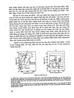
THE VERSATILITY OF
ROUND INSERT CUTTERS
If the rough milling of a cavity is done
with a square shoulder cutter much stair-
case shaped stock has to be removed in
semi-finishing. This of course creates
varying cutting forces and tool deflec-
tion. The result is an uneven stock for
finishing, which will influence the geo-
metrical accuracy of the die or mould.
are usually first choice for all operations.
But, it is definitely possible to compete
in productivity also by using inserted
tools with specific properties. Such as
round insert cutters, toroid cutters and
ballnose end mills. Each case has to be
individually analysed
To reach maximum productivity it is
also important to adapt the size of the
milling cutters and the inserts to a certain
die or mould and to each specific opera-
tion. The main target is to create an
evenly distributed working allowance
(stock) for each tool and in each ope-
ration. This means that it is most often
more favourable to use different dia-
meters on cutters, from bigger to smal-
ler, especially in roughing and semi-
finishing. Instead of using only one dia-
meter throughout each operation. The
ambition should always be to come as
close as possible to the final shape of
the die or mould in each operation.
An evenly distributed stock for each
tool will also guarantee a constant and
high productivity. The cutting speed
and feed rate will be on constant high
levels when the ae/ap is constant. There
will be less mechanical variations and
work load on the cutting edge. Which
in turn gives less heat generation, fati-
gue and an improved tool life.
A constant stock also enables for higher
cutting speed and feed together with a
very secure cutting process. Some semi-
finishing operations and practically all
finishing operations can be performed
unmanned or partially manned. A con-
stant stock is of course also one of the
real basic criterias for HSM.
Another positive effect of a constant
stock is that the impact on the machine
tool - guide ways, ball screws and spind-
le bearings will be less negative. It is
also very important to adapt the size
and type of milling cutters to the size of
the machine tool.
tools and holding and cutting tools, to
eliminate manual polishing even up to
100%. If using the strategy to do roug-
hing and finishing in separate machines
it can be a good solution to use fixturing
plates. The die or mould can then be lo-
cated in an accurate way. If doing 5-sided
machining it is often necessary to use
fixturing plates with clamping from be-
neath. Both the plate and the blank must
be located with cylindrical guide pins.
The machining process should be divi-
ded into at least three operation types;
roughing, semi-finishing and finishing,
some times even super-finishing (mostly
HSM applications). Restmilling opera-
tions are of course included in semi-
finishing and finishing operations.
Each of these operations should be
performed with dedicated and optimi-
sed cutting tool types.
In conventional die & mould making it
generally means:
Roughing Round insert cutters,
end mills w. big corner
radii
Semi-finishing Round insert cutters,
toroid cutters, ball nose
endmills
Finishing Round insert cutters
(where possible), toroid
cutters, ball nose end-
mills (mainly)
Restmilling Ballnose endmills, end-
mills, toroid and round
insert cutters
In high speed machining applications it
may look the same. Especially for big-
ger sized dies or moulds.
In smaller sizes, max 400 X 400 X 100
(l,w,h), and in hardened tool steel, ball
nose end mills (mainly solid carbide)
Metalworking World
If a square shoulder cutter with triang-
ular inserts is used it will have relatively
weak corner cross sections, creating an
unpredictable machining behaviour.
Triangular or rhombic inserts also cre-
ates big radial cutting forces and due to
the number of cutting edges they are
less economical alternatives in these
operations.
On the other hand if round inserts,
which allows milling in all materials
and in all directions, are used this will
give smooth transitions between the
passes and also leaves less and more
even stock for the semi-finishing. Re-
sulting in a better die or mould quality.
Among the features of round inserts is
that they create a variable chip thick-
ness. This allows for higher feed rates
compared with most other insert shapes.
The cutting action of round inserts is also
very smooth as the entering angle suc-
cessively alters from nearly zero (very
Stock to be
removed
“Stair case
shaped” stock
shallow cuts) to 90 degrees. At maxi-
mum depth of cut the entering angle is
45 degrees and when copying with the
periphery the angle is 90 degrees. This
also explains the strength of round in-
serts - the work-load is built up succes-
sively.
Round inserts should always be regar-
ded as first choice for roughing and me-
dium roughing operations. In 5-axis
machining round inserts fit in very well
and have practically no limitations.
With good programming round insert
cutters and toroid cutters can replace
ball nose end mills to a very big extent.
The productivity increase most often
ranges between 5-10 times (compared
with ball nose end mills). Round insert
cutters with small run-outs can in com-
bination with ground, positive and light
cutting geometries also be used in
semi-finishing and some finishing ope-
rations. Ballnose endmills, on the other,
hand can never be replaced in close
semi-finishing and finishing of complex
3D (shapes) geometries.
In the next article in the Die & Mould
series “Application technologies” will
be put in focus.
Square shoulder
cutter, 90°
Much material
remaining
after roughing
Stock to be
removed
Round insert cutter
Less
material
remaining
after roughing
Combination
of milling directions
Smooth
transitions-
little stock
Metalworking World
24
25
Metalworking World
the feed rate as it is dependent on the
spindle speed for a certain cutting speed.
If using the nominal diameter value of
the tool, when calculating cutting speed,
the effective or true cutting speed will
be much lower if the depth of cut is
shallow. This is valid for tools such as,
round insert cutters (especially in the
small diameter range), ball nose end
mills and end mills with big corner radii.
EFFECTIVE DIAMETER IN CUT
This is very much a question about
optimising cutting data, grades and geo-
metries in relation to the specific type
of material, operation and productivity
and security demands.
It is always important to base calcula-
tions of effective cutting speed on the
true or effective diameter in cut. If not,
there will be severe miscalculations of
I
n this fifth article about die and mould making
from Sandvik Coromant, application technology
will be in focus. Some basic, but none the less very
important parameters, will be discussed. Examples
are down milling, copy milling and the importance
of as little tool deflection as possible.
Application technology
The feed rate will of course also be
much lower and the productivity seve-
rely hampered.
Most important is that the cutting con-
ditions for the tool will be well below
its capacity and recommended applica-
tion range. This often leads to prema-
ture frittering and chipping of the cut-
ting edge due to too low cutting speed
and heat in the cutting zone.
AVOID EXCESSIVE DEFLECTION
When doing finishing or super-finishing
with high cutting speed in hardened
tool steel it is important to choose tools
that have a coating with high hot hard-
ness. Such as TiAlN.
One main parameter to observe when
finishing or super-finishing in harde-
ned tool steel with HSM is to take shal-
low cuts. The depth of cut should not
exceed 0,2/0,2 mm (a
p
/a
e
). This is to
avoid excessive deflection of the hol-
ding/ cutting tool and to keep a high
tolerance level and geometrical accu-
racy on the machined die or mould.
Choose very stiff holding and cutting
tools. When using solid carbide it is im-
portant to use tools with a maximum
core diameter (big bending stiffness).
When using inserted ball nose end mills,
for instance, it is favourable to use
tools with shanks made of heavy metal
(big bending stiffness). Especially if
the ratio overhang/diameter if large.
1000
800
600
400
0
TiAIN TiCN TiN Uncoated
a
p
/a
e
Ϲ 0,2
26
Metalworking World
DOWN MILLING IS IMPORTANT
Another application parameter of im-
portance is the use of down milling
tool paths as much as possible. It is,
nearly always, more favourable to do
down milling than up milling. When the
cutting edge goes into cut in down mil-
ling the chip thickness has its maximum
heat is generated as the cutting edge is
exposed to a higher friction than in
down milling. The radial forces are also
considerably higher in up milling, which
affects the spindle bearings negatively.
In down milling the cutting edge is
mainly exposed to compressive stresses,
which are much more favourable for
the properties of cemented or solid car-
bide compared with the tensile stresses
developed in up milling.
When doing side milling (finishing)
with solid carbide, especially in harde-
ned materials, up milling is first choice.
It is then easier to get a better tolerance
on the straightness of the wall and also
a better 90 degree corner. The mismatch
between different axial passes will also
be less, if none.
value. In up milling this is when it has
its minimum value. The tool life is
generally shorter in up milling than in
down-milling due to the fact that there
is considerably more heat generated in
up-, than in down milling. When the
chip thickness in up milling increases
from zero to maximum the excessive
Bending Roughing Finishing
Upmilling - 0.02 mm 0.00 mm
Downmilling 0.06 mm 0.05 mm
Roughing
Finishing
Downmilling Upmilling
DU
V
ƒ
V
ƒ
Endmills with a higher helix angle have less radial forces and usually run smoother. Endmills with a
higher helix angle has more axial forces and the risk of being pulled out from the collet is greater.
Solid Carbide Endmills - Finishing/Deflection
Example based on zero degree entering angle.
27
Metalworking World
a risk for vibration, deflection or even
tool breakage if the feed speed does not
decelerate fast enough. There is also
a risk of pulling the cutter from the
holder due to the direction of the cut-
ting forces.
The most critical area when using ball
nose end mills is the centre portion.
Here the cutting speed is zero, which is
very disadvantageous for the cutting
process. Chip evacuation in the centre
is also more critical due to the small
space at the chisel edge. Avoid using
the centre portion of a ball nose end
mill as much as possible. Tilt the spindle
or the workpiece 10 to 15 degrees to
get ideal cutting conditions. Sometimes
this also gives the possibility to use
shorter (and other type of) tools.
If the spindle speed is limited in the
machine, contouring will help to keep
up the cutting speed. This type of tool
path also creates less quick changes in
work load and direction. This is of spe-
cific importance in HSM applications
and hardened materials as the cutting
speed and feed are high and the cutting
edge and process is more vulnerable to
any changes that can create differences
in deflection and create vibrations. And
ultimately total tool breakdown.
This is mainly due to the direction of
the cutting forces. With a very sharp
cutting edge, the cutting forces tend to
“pull” or “suck” the cutter towards the
material.
Up- milling can be favourable when
having old manual milling machines
with large play in the lead screw, because
a “counter pressure” is created which
stabilizes the machining.
The best way to ensure down- milling
tool paths in cavity milling is to use con-
touring type of tool paths. Contouring
with the periphery of the milling cutter
(for instance a ball nose end mill) often
results in a higher productivity, due to
more teeth effectively in cut on a larger
tool diameter.
COPY MILLING AND PLUNGING
Copy milling and plunging operations
along steep walls should be avoided as
much as possible! When plunging, the
chip thickness is large at a low cutting
speed. This means a risk of frittering at
the centre, especially when the cutter
hits the bottom area. If the control has
no, or a poor, look ahead function the
deceleration will not be fast enough
and there will most likely be damage
on the centre.
It is somewhat better for the cutting pro-
cess to do up-copying along steep walls
as the chip thickness has its maximum
at a more favourable cutting speed.
But, there will be a big contact length
when the cutter hits the wall. This means
Large chip thickness at very low v
c
. Max chip thickness at recommended v
c
.
The tool-life will be considerably shor-
ter if the tool has many entries and
exits in the material. This adds the
amount of thermal stresses and fatigue
in the cutting edge. It is more favoura-
ble for modern cemented carbide to
have an even and high temperature in
the cutting zone than having big fluc-
tuations.
Copy milling tool paths are often a mix
of up-, and down milling (zig-zag) and
gives a lot of engagements and disen-
gagements in cut. This is, as mentioned
above, not favourable for any milling
cutter, but also harmful for the quality
of the die or mould. Each entrance
For a long tool-life, it is also more
favourable in a milling process to stay
in cut continuously and as long as pos-
sible. All milling operations have inter-
rupted or intermittent character cuts
due to the usage of multi-teeth tools.
means that the tool will deflect and
there will be an elevated mark on the
surface. This is also valid when the tool
exits. Then the cutting forces and the
bending of the tool will decrease and
there will be a slight undercutting of
material in the exit portion.
These factors also speak for contou-
ring and down milling tool paths as the
preferred choice.
SCULPTURED SURFACES
In finishing and super-finishing,
especially in HSM applications, the
target is to reach a good geometri-
cal and dimensional accuracy and
reduce or even eliminate all manual
polishing.
In many cases it is favourable to
choose the feed per tooth, f
z
, identi-
cal with the radial depth of cut, a
e
(f
z
= a
e
).
This gives the following
advantages:
• very smooth surface finish
in all directions
• very competitive, short machi-
ning time
• very easy to polish, symmetrical
surface texture, self detecting
character via peaks and valleys
• increased accuracy and
bearing resistance on surface
gives longer tool
life on die or mould
• minimum cusp or scallop height
decides values on f
z
/a
e
/R
If you have any questions regar-
ding die & mould making, send an
e-mail to:
28
Metalworking World
29
roughing and finishing steel and where
vibration tendencies are a threat to the
result of the operation.
Coarse pitch is the true problem solver
and is the first choice for milling with
long overhang, low powered machines
or other applications where cutting
forces must be minimized.
(C) Extra-close pitch cutters have small
chip pockets and permits very high
table feeds. These cutters are suitable
for machining interrupted cast-iron
surfaces, roughing cast-iron and small
depth of cut in steel. Also in materials
where the cutting speed has to be kept
low, for instance in titanium. Extra close
pitch is the first choice for cast iron.
The milling cutters can have either
even or differential pitch. The latter
one means unequal spacing of teeth
round the cutter and is a very effective
means of coming to terms with pro-
blems of vibrations.
(A) Close pitch means more teeth and
moderate chip pockets and permits
high metal-removal rate. Normally
used for cast-iron and for medium duty
machining operations in steel. Close
pitch is the first choice for general pur-
pose milling and is recommended for
mixed production.
CUTTER PITCH
A milling cutter, being a multi-edge
tool, can have a variable number of
teeth (z) and there are certain factors
that help to determine the number for
the type of operation. The material and
size of workpiece, stability, finish and
the power available are the more ma-
chine orientated factors while the tool
related include sufficient feed per tooth,
at least two cutting edges engaged in
cut simultaneously and that the chip
capacity of the tool is ample.
The pitch (u) of a milling cutter is the
distance between a point on the edge to
the same point on the next edge. Milling
cutters are classified into coarse, close
or extra-close pitch cutters and most
cutters have these three options.
Knowing the process
parameters
Metalworking World
I
n this article in the series about die and mould
making some basic factors of the milling
process will be discussed, as well as some trouble
shooting hints. It is important to know basic
milling factors such as cutter pitch, entrance and
exit of cut, positioning of the cutter, extended tools
and how these parameters influence the cutting
process in order to facilitate the understanding in
upcoming articles.
(B) Coarse pitch means fewer teeth on
the cutter periphery and large chip
pockets. Coarse pitch is often used for
A
C
B
u
30
ENTRANCE AND EXIT OF CUT
Every time a cutter goes into cut, the
inserts are subjected to a large or small
shock load depending on material, chip
cross section and the type of cut. The
initial contact between the cutting edge
and workpiece may be very unfavoura-
ble depending on where the edge of
the insert has to take the first shock.
Because of the wide variety of possible
types of cut, only the effects of the cut-
ter position on the cut will be conside-
red here.
Where the centre of the cutter is posi-
tioned outside the workpiece (D) an
unfavourable contact between the edge
of the insert and the workpiece results.
Where the centre of the cutter is posi-
tioned inside the workpiece (E) the
most favourable type of cut results.
The most dangerous situation howe-
ver, is when the insert goes out of cut
leaving the contact with the workpie-
ce. The cemented carbide inserts are
made to withstand compressive stres-
ses which occur every time an insert
goes into cut (down milling). On the
other hand, when an insert leaves the
workpiece when hard in cut (up mil-
ling) it will be affected by tensile stres-
ses, which are destructive for the insert
which has low strength against this
type of stress. The result will often end
in rapid insert failure.
seats, the inserts sitting in the seats
which are not being in cut can be
ground down and allowed to remain in
the cutter as dummy inserts.
POSITIONING AND
LENGTH OF CUT
The length of cut is affected by the
positioning of the milling cutter. Tool-
life is often related to the length of cut
which the cutting edge must undergo.
A milling cutter which is positioned in
the centre of the workpiece gives a
shorter length of cut, while the arc which
is in cut (␣) will be longer if the cutter
is moved away from the centre line (B)
in either direction.
Bearing in mind how the cutting forces
act, a compromise must be reached.
The direction of the radial cutting for-
ces (A) will vary when the insert edges
go into and out of cut and play in the
machine spindle can give rise to vibra-
tion and lead to insert breakage.
By moving the milling cutter off the
centre, B and C, a more constant and
favourable direction of the cutting for-
ces will be obtained. With the cutter
positioned close to the centre line the
largest average chip thickness is obtai-
ned. With a large facemill it can be
advantageous to move it more off cen-
tre. In general, when facemilling, the
cutter diameter should be 20-25% lar-
ger than the cutting width.
When there is a problem with vibra-
tion it is recommended that a milling
cutter with as coarse pitch as possible
is used, so that fewer inserts give less
opportunities for vibration to arise.
You can also remove every second in-
sert in the milling cutter so that there
are fewer inserts in cut. In full slot mil-
ling you can take out so many of the
inserts that only two remain. However,
this means that the cutter being used
must have an even number of teeth, 4,
6, 8, 10 etc. With only two inserts in the
milling cutter, the feed per tooth can
be increased and the depth of cut can
usually be increased several times. The
surface finish will also be very good. A
surface finish of Ra 0.24 in hardened
steel with a hardness of 300 HB has
been measured after machining with a
milling cutter with an overhang of 500
mm. In order to protect the insert
Metalworking World
E D
31
of the die or mould decides where to
change.
Cutting data should also be adapted to
each tool length to keep up maximum
productivity.
When the total tool length, from the
gauge line to the lowest point on the
cutting edge, exceeds 4-5 times diame-
ter at the gauge line, tuned, tapered bars
should be used. Or, if the bending stiff-
ness must be radically increased, ex-
tensions made of heavy metal should
be used.
When using extended tools it is impor-
tant to choose biggest possible diame-
ter on the extensions and adapters
relatively to the cutter diameter. Every
millimetre is important for maximum
rigidity, stiffness and productivity. It is
not necessary to have more than 1 mm
radially in difference between holding
and cutting tool. The easiest way to
achieve this is to use oversized cutters.
Modular tools increases the flexibility
and the number of tool combination
possibilities.
EXTENDED TOOLS
IN ROUGHING OF A CAVITY
To maintain maximum productivity
when roughing a cavity it is important
to choose a series of extensions for the
cutter. It is a very bad compromise to
Metalworking World
start with the longest extension, as the
productivity will be very low.
It is recommendable to change to ex-
tended tools at pre-determined posi-
tions in the program. The geometry
32
Metalworking World
TROUBLE SHOOTING
The basic action to be taken when there is a problem with vibration is to reduce the
cutting forces. This can be done by using the correct tools and cutting data.
Choose milling cutters with coarse and differential pitch.
Use positive insert geometries.
Use as small milling cutter as possible. This is particularly important when milling with
tuned adapters.
Small edge rounding (ER). Go from a thick coating to a thin one, if necessary use uncoated
inserts.
Use a large feed per tooth, reduce the rotational speed and maintain the table feed
(= larger feed per tooth). Or maintain the rotational speed and increase the table feed
(= larger feed per tooth). Do not reduce the feed per tooth!
Reduce the radial and axial cutting depths.
Choose a stable tool holder. Use the largest possible adapter size to achieve the best
stability. Use tapered extensions for best rigidity.
With long overhangs, use tuned adapters in combination with coarse and differential
pitched cutters. Position the milling cutter as close to the tuned adapter as possible.
Position the milling cutter off centre of the workpiece, which leads to a more favourable
direction of the cutting forces.
Start with normal feed and cutting speed. If vibrations arises try introducing these
measures gradually, as previously described:
a) increase the feed and keep the same rpm
b) decrease the rpm and keep the same feed
c) reduce the axial or/and radial depth of cut
d) try to reposition the cutter
33
Metalworking World
Axially weak workpiece
Establish the direction of the cutting forces and position the material
accordingly.
Try to improve the clamping generally.
Reduce the cutting forces by reducing the radial and axial cutting depth.
Choose a milling cutter with a coarse pitch and positive design.
Choose positive inserts with small corner radius and small parallel lands.
Where possible, choose an insert grade with a thin coating and sharp
cutting edge. If, necessary, choose an uncoated insert grade.
Avoid machining where the workpiece has poor support against cutting
forces.
The first choice is a square shoulder facemill with positive insets.
Choose an insert geometry with sharp cutting edge and a large clearance
angle, which produces low cutting forces.
Try to reduce the axial cutting forces by reducing the axial depth of cut,
as well as using positive inserts with a small corner radius, small parallel
lands and sharp cutting edges.
Always use a coarse and differentially pitched milling cutter.
Balance the cutting forces axially and radially. Use a 45-degree entering
angle, large corner radius or round inserts.
Use inserts with a light cutting geometry.
Try to reduce the overhang, every millimetre counts.
Choose the smallest possible milling cutter diameter in order to obtain the
most favourable entering angle. The smaller diameter the milling cutter
has the smaller the radial cutting forces will be.
Choose positive and light cutting geometries.
Try up milling.
Try up milling.
Look at the possibility of adjusting the prestress of the washer to the ball-
screw (CNC). Adjust the lock nut or exchange the screw on conventional
machines.
Cause
Poor clamping of the workpiece
Action
Uneven table feed
Large overhang either on the
machine spindle or the tool
Square shoulder milling with a
radially weak machine spindle
34
any definite stop at block borders.
Which means that the movement gives
smooth continuous transitions and there
is only a small chance that a vibration
should start.
• Another solution is to produce a big-
ger corner radius, via circular interpo-
lation, than stated in the drawing. This
can be favourable sometimes as it
allows to use a bigger cutter diameter
in roughing to keep up maximum pro-
ductivity.
In traditional machining of corners the
tool radius is identical with the corner
radius. Which gives maximum contact
length and deflection (often one qua-
drant).
The most typical result is vibrations,
the bigger the longer the tool, or total
tool overhang is. The wobbling cutting
forces often also creates undercutting
of the corner. There is of course also a
risk for frittering of edges or total tool
break down.
METHODS FOR
MACHINING OF CORNERS
The traditional way of machining a
corner is to use linear movements (G1)
with non-continuous transitions in the
corner. Which means that when the
cutter comes to the corner it has to be
slowed down because of dynamic limi-
tations of the linear axes. And there
will even be a very short stop before the
motors can change the feed direction.
As the spindle speed is the same, the
situation creates a lot of excessive fric-
Effective machining
of corners & cavities
Metalworking World
T
his is the last article in this series about die and
mould making from Sandvik Coromant. In
this article the most efficient way to machine cor-
ners are discussed as well as different methods for
machining of cavities. Finally the advantages of
machining in segments is also discussed.
Some solutions on this problem are:
• Use a cutter with a smaller radius to
produce the desired corner radius on
the die or mould. Use circular interpo-
lation (G2, G3) to produce the corner.
This movement type does not create
• The remaining stock in the corner
can then be machined via restmilling
(rest = remaining stock) with a smaller
cutter radius and circular interpola-
tion. The restmilling of corners can also
be performed by axial milling. It is im-
tion and heat. If for instance alumini-
um or other light alloys are machined
they can get burning marks or even
start to burn due to this heat. The sur-
face finish will deteriorate optically and
in some materials even structurally,
even beyond the tolerance demands.
Stock
to
remove
Ø8
R10
R4
35
13 degrees. Whilst an 80 mm cutter
manages 3.5 degrees. The amount of
clearance also depends upon the dia-
meter of the cutter.
Often used within die & mould making
is when the tool is fed in a spiral sha-
ped path in the axial direction of the
spindle, while the workpiece is fixed.
This is most common when boring and
have several advantages when machi-
ning holes with large diameters. First
of all the large diameter can be machi-
ned with one and the same tool, se-
condly chip breaking and evacuation
is usually not a problem when machi-
ning this way, much because of the
portant to use a good programming
technique with a smooth approach and
exit. It is very important to perform the
restmilling of corners before or as a
semi-finishing operation - gives even
stock and high productivity in finishing.
If the cavity is deep (long overhang)
the a
p
/a
e
should be kept low to avoid
deflection and vibration (a
p
/a
e
appr.
0,1-0,2 mm in HSM applications in
hardened tool steel).
If consequently using a programming
technique based on circular interpola-
tion (or NURBS-interpolation), which
gives both continous tool paths and
commands of feed and speed rates, it is
possible to drive the mechanic functions
of a machine tool to much higher speeds,
accelerations and decelerations.
This can result in productivity gains
ranging between 20-50%!
RAMPING AND
CIRCULAR INTERPOLATION
Axial feed capability is an advantage
in many operations. Holes, cavities as
well as contours can be efficiently ma-
chined. Facemilling cutters with round
inserts are strong and have big clearan-
ce to the cutter body.
Metalworking World
Those lend themselves to drill/mill
operations of various kinds. Ramping
at high feed rates and the ability to
reach far into workpieces make round
insert cutters a good tool for complica-
ted forms. For instance, profile milling
in five-axis machines and roughing in
three-axis machines.
Ramping is an efficient way to appro-
ach the workpiece when machining
pockets and for larger holes circular
interpolation is much more power effi-
cient and flexible than using a large
boring tool. Problems with chip control
are often eliminated as well.
When ramping, the operation should
be started around the centre, machining
outwards in the cavity to facilitate chip
evacuation and clearance. As milling
cutters has limitations in the axial depth
of cut and varies depending on the dia-
meter, the ramping angle for different
sizes of cutters should be checked.
The ramping angle is dependent upon
the diameter of the cutters used, clea-
rance to the cutter body, insert size and
depth of cut. A 32 mm CoroMill 200
cutter with 12 mm inserts and a cutting
depth of 6 mm can ramp at an angle of
smaller diameter of the tool compared
to the diameter of the hole to be ma-
chined and third, the risk of vibration
is small.
It is recommended that the diameter
of the hole to be machined is twice the
diameter of the cutter. Remember to
check maximum ramping angle for the
cutter when using circular interpola-
tion as well.
These methods are favourable for weak
machine spindles and when using long
overhangs, since the cutting forces are
mainly in the axial direction.
MACHINING IN SEGMENTS
When machining huge press dies it is
often necessary to index the inserts
several times. Instead of doing this
manually and interrupting the cutting
process, this can be done in an organi-
sed way if precautions are taken in the
process planning and programming.
Based on experience, or other infor-
mation, the amount of material, or the
surface to machine, can be split up in
portions or segments. The segments,
or several segments, can be chosen
according to natural boundaries or be
based on certain radii sizes in the die or
mould. What is important is that each
segment can be machined with one set
of insert edges or solid carbide edges,
plus a safety margin, before being
changed to next tool in that specific
family of replacement tools.
This technique enables full usage of
the ATC (Automatic Tool Changer)
and replacement tools (sister tools).
The technique can be used for roug-
hing to finishing. Today’s touch probes
or laser measuring equipment gives
very precise measuring of tool diame-
ter and length and a matching (of sur-
faces) lower than 10 microns. It also
gives several benefits such as:
• Better machine tool utilisation- less
interruptions, less manual tool
changing
• Higher productivity-easier to optimise
cutting data
• Better cost efficiency-optimisation vs
real machine tool cost per hour
• Higher die or mould geometrical
accuracy-the finishing tools can be
changed before getting excessive wear
METHODS FOR MACHINING OF A CAVITY
A. Pre-drilling of a starting hole. Corners can
be pre-drilled as well. Not recommendable
method as one extra tool is needed. Which
also adds more unproductive positioning and
tool changing time. The extra tool also blocks
one position in the tool magazine. From a
cutting point of view the variations in cutting
forces and temperature when the cutter breaks
through the pre-drilled holes in the corners is
negative. The re-cutting of chips also increa-
ses when using pre-drilled holes.
B. If using a ball nose end mill, inserted or
solid carbide, it is common to use a peck-dril-
ling cycle to reach a full axial depth of cut
and then mill the first layer of the cavity. This
is then repeated until the cavity is finished.
The drawback with this start is chip evacua-
tion problems in the centre of the end mill.
Better than using a peck-drilling cycle is to
reach the full axial depth of cut via circular
interpolation in helix. Important also then to
help evacuate the chips.
C. One of the best methods is to do linear
ramping in X/Y and Z to reach a full axial
depth of cut. Note that if choosing the right
starting point, there will be no need of milling
away stock from the ramping part. The ram-
ping can start from in to out or from out to in
depending on the geometry of the die or
mould. The main criteria is how to get rid of
the chips in the best way. Down milling should
be practised in a continuous cutting. When
taking a new radial depth of cut it is impor-
tant to approach with a ramping movement
or, better, with a smooth circular interpola-
tion. In HSM applications this is crucial.
D. If using round insert cutters or end mills
with a ramping capacity the most favourable
method is to take the first axial depth of cut
via circular interpolation in helix and follow
the advice given in the previous point.
C-5000:329
9911
Printed in Sweden
CMSE/Idéreklam/Sjöströms/Sandvikens Tryckeri
Peck-drilling cycle with
a short delay between
each down-feed to
evacuate chips.
Required
depth of
cut for
machining
the first
layer.
A
B
C
D