Handbook Of Shaft Alignment Episode 3 Part 2 pot
Bạn đang xem bản rút gọn của tài liệu. Xem và tải ngay bản đầy đủ của tài liệu tại đây (1.42 MB, 30 trang )
conditions as shown in the lower illustration in Figure 18.17. Adjustments to the machines
may therefore require precise, controlled moves in the vertical, lateral, and axial directions.
18.9 USING A STRAIGHTEDGE TO MEASURE MISALIGNMENT
Belt and sheave driven equipment poses a slightly different type of alignment problem than
equipment directly coupled together. The basic objective is to insure that the shaft centerlines
are parallel to each other.
FIGURE 18.12 Rim runout check on sheave.
Piotrowski / Shaft Alignment Handbook, Third Edition DK4322_C018 Final Proof page 600 28.9.2006 7:15pm
600 Shaft Alignment Handbook, Third Edition
For decades, the most widely used alignment tool is either a string or a straightedge. Today
there are far more elaborate ways to perform belt–sheave alignment as shown later in this
chapter, but most often, acceptable belt alignment can be accomplished using a simple
straightedge. Bear in mind that most manufacturers of belt and sheave drives suggest that
the sheaves should be aligned to within 1=8 in. per foot distance between shaft centerlines.
That is about 11 mils=in., much more forgiving that direct drive systems, which are typically
aligned to around 1 mil=in.
FIGURE 18.13 Face runout check on sheave.
Piotrowski / Shaft Alignment Handbook, Third Edition DK4322_C018 Final Proof page 601 28.9.2006 7:15pm
Aligning V-Belt Drives 601
Straightedges work fine for distances under 4 ft but when the distance between the driver
shaft and the driven shaft begin to exceed that, a string should probably be used. One tool
developed by Max Roeder called the A-String works extremely well and produces very accurate
results shown in Figure 18.18 and Figure 18.19. The A-String has an adjustable base
that enables one to compensate for centerline offset of sheaves as shown in Figure 18.20. To
properly align sheaves, you must compensate for any difference in the actual center of the V in
each sheave. Measure the width of the groove; then measure the flange outer thickness on each
sheave to determine what the offset may have to be if the outer flange widths are not the same.
FIGURE 18.14 Rim runout check on sheave.
Piotrowski / Shaft Alignment Handbook, Third Edition DK4322_C018 Final Proof page 602 28.9.2006 7:15pm
602 Shaft Alignment Handbook, Third Edition
FIGURE 18.15 Face runout check on sheave.
FIGURE 18.16 Bent sheave.
Piotrowski / Shaft Alignment Handbook, Third Edition DK4322_C018 Final Proof page 603 28.9.2006 7:15pm
Aligning V-Belt Drives 603
18.10 MEASURING THE MISALIGNMENT AT THE SHEAVES
To measure the amount of offset, pitch, and skew that exists between the shafts and their
sheaves, measurements with a straightedge need to be taken at two different places on the
outer surface of the sheaves as shown in Figure 18.21. Measure the distances across each
sheave at the upper and lower gap measurement locations. Determine what type of gap
condition you have based on the four different configurations shown in Figure 18.22. Using
feeler gauges, measure and record the amount of the gaps (in mils) between the straightedge
and the surface of the sheaves as shown in Figure 18.23 and Figure 18.24.
18.11 V-BELT MACHINE MEASUREMENTS
In addition to the gap measurements taken on the sheaves as shown in Figure 18.21 through
Figure 18.24, dimensional measurements of the two machines need to be taken as shown in
Offset—the shafts are parallel to each
other and in the X−Y plane but one
shaft/sheave is to the right of left of the
other shaft/sheave in the Y direction
Pitch—the shafts are in the X−Y plane
but one shaft/sheave is rotated through
the Z-axis
Skew—the shafts are not in the same
plane and one shaft/sheave is rotated
through the X-axis
X
Y
Z
Combination—this is the most
common type of misalignment
condition (and the most complex)
where the shafts are not in the
same plane and one shaft/sheave
is rotated through both the X-
and Z-axis
FIGURE 18.17 (See color insert following page 322.) Types of belt and sheave misalignment conditions.
Piotrowski / Shaft Alignment Handbook, Third Edition DK4322_C018 Final Proof page 604 28.9.2006 7:15pm
604 Shaft Alignment Handbook, Third Edition
Figure 18.25. A recording sheet shown in Figure 18.26 can be used to record all the required
information to generate an alignment model of the misalignment condition.
18.12 MODELING V-BELT ALIGNMENT PROBLEMS
Alignment models can also be used to visualize the misalignment condition on belt and sheave
drive equipment. You will have to generate two different views of your drive system. One view
will be generated from above (i.e., the top view), which will show any offset and pitch
conditions between the two sheaves. The end view will show any offset and skew conditions
that exist between the two sheaves. You can use two T-bar overlays (see Face–Rim graphing
method on Chapter 11) to represent each shaft=sheave.
FIGURE 18.18 A-String sheave alignment tool.
Piotrowski / Shaft Alignment Handbook, Third Edition DK4322_C018 Final Proof page 605 28.9.2006 7:15pm
Aligning V-Belt Drives 605
18.13 V-BELT ALIGNMENT MODELING SAMPLE PROBLEM
Figure 18.27 shows an electric motor driving a fan. The critical dimensions needed to generate
an alignment model of this drive system are shown in Figure 18.27. Use one of the T-bar
overlays to scale off the distance from the inboard-to-outboard bolts of the motor (15 in.) and
the distance from the inboard bolt of the motor to the edge of the sheave where the straight-
edge measurements are taken (5 in.). On the top of the T-bar overlay, scale off the 6 in.
distance to represent where the straightedge gaps or contact point were measured. Similarly
for the fan, use the other T-bar overlay to scale off the distance from the inboard-to-outboard
bolts of the fan (12 in.) and the distance from the inboard bolt of the fan to the edge of the
sheave where the straightedge measurements are taken (4 in.). On the top of the T-bar
overlay, scale off the 8 in. distance to represent where the straightedge gaps or contact points
were measured.
FIGURE 18.19 A-String sheave alignment tool.
Piotrowski / Shaft Alignment Handbook, Third Edition DK4322_C018 Final Proof page 606 28.9.2006 7:15pm
606 Shaft Alignment Handbook, Third Edition
Figure 18.28 shows the top view of the motor and fan shafts. Notice that you want to pitch
each T-bar overlay at the midpoint between the gap you measured at the top of each sheave and
the gap you measured at the bottom of each sheave. In the case of the motor sheave gaps,
the upper gap was 10 mils and the lower gap was 16 mils. (10 þ16 mils ¼ 26 mils; 26 mils=2 ¼
13 mils, i.e., the midpoint). In the case of the fan sheave gaps, the upper gap was 26 mils and the
lower gap was 8 mils. (26 þ 8 mils ¼ 34 mils; 34 mils=2 ¼ 17 mils, i.e., the midpoint). Notice
that the motor shaft and fan shaft are not parallel to each other.
Figure 18.29 shows the end view of the motor and fan shafts. In this view, the motor is
toward us and the fan is away from us. Also notice that in this particular case, the distance
from the upper to lower straightedge measurements on the motor was 6 in., the same distance
the straightedge measurements were taken from the inboard-to-outboard edge of the motor
as shown in the top view. If the distance from the upper to lower straightedge measurements is
not the same as it was between the inboard and outboard edges, you must scale off whatever
the upper to lower straightedge measurements actually were when viewing the shafts and
sheaves in the end view. Again, notice that you want to pitch each T-bar overlay at the
midpoint between the gap you measured at the top (upper edge) of each sheave and the gap
you measured at the bottom (lower edge) of each sheave. In the case of the motor sheave gaps,
the upper gap was 10 mils and the lower gap was 16 mils. The midpoint at the upper edge of
the motor sheave is 5 mils, and the midpoint at the lower edge of the motor sheave is 5 mils.
The T-bar for the motor should be pitched to intersect the midpoint at its upper and lower
Sheave outer
flange width
is different
FIGURE 18.20 Measuring centerline offset of sheaves.
Piotrowski / Shaft Alignment Handbook, Third Edition DK4322_C018 Final Proof page 607 28.9.2006 7:15pm
Aligning V-Belt Drives 607
points. In the case of the fan sheave gaps, the upper gap was 26 mils and the lower gap was
8 mils. The midpoint at the upper edge of the fan sheave is 13 mils, the midpoint at the lower
edge of the fan sheave is 4 mils. The T-bar for the fan should be pitched to intersect the
midpoint at its upper and lower points.
Why do we position the T-bar overlays at the midpoints of the gaps? Because the actual
centerline of rotation is midway between the 6 in. (on the motor) and 8 in. (on the fan)
measurement points where the straightedge was positioned on each sheave. Graphically,
the top of the T-bar overlay is represented as a straight line. When viewing the sheaves
from the top or end views, the sheaves would actually appear as ellipses.
Straightedge
____ inches
____ inches
____ inches
_
___ inches
Straightedge
Sheave measurement
distances with straightedge in
upper position
Sheave measurement
distances with straightedge in
lower position
Upper to lower straightedge
separation distances across
each sheave
___ inches ___ inches
FIGURE 18.21 Measure the gap conditions on the sheaves at two different locations.
Piotrowski / Shaft Alignment Handbook, Third Edition DK4322_C018 Final Proof page 608 28.9.2006 7:15pm
608 Shaft Alignment Handbook, Third Edition
FIGURE 18.22 Four possible gap conditions.
Upper position gap readings
___ mils
___ mils
___ mils
___ mils
___ mils
___ mils
___ mils
___ mils
Determine where the
straightedge is touching on
each sheave. Measure and
record the gaps on each
sheave in one of the four
conditions below.
Touching or gap?
FIGURE 18.23 Measure the gap conditions at the top of the sheaves.
Piotrowski / Shaft Alignment Handbook, Third Edition DK4322_C018 Final Proof page 609 28.9.2006 7:15pm
Aligning V-Belt Drives 609
Lower position gap readings
___ mils
___ mils
___ mils
___ mils
___ mils
___ mils
___ mils
___ mils
Determine where the
straightedge is touching on
each sheave. Measure and
record the gaps on each
sheave in one of the four
conditions below.
Touching or gap?
FIGURE 18.24 Measure the gap conditions at the bottom of the sheaves.
Machine name
O North
O South
O East
O West
O Up
O Down
Machine name
O North
O South
O East
O West
O Up
O Down
• Measure the distance between the outboard and inboard bolts
of both machines
• Measure the distance from the inboard feet to where the
straightedge will be placed to capture the gap readings on
the sheaves
• Measure the distance between the shaft centerlines
Measure the dimensions of the machinery
FIGURE 18.25 Dimensional measurements of the machines.
Piotrowski / Shaft Alignment Handbook, Third Edition DK4322_C018 Final Proof page 610 28.9.2006 7:15pm
610 Shaft Alignment Handbook, Third Edition
To correct the misalignment (i.e., nonparallelism) between the motor and fan shafts in the
top view, the next step would be to determine the allowable lateral movement envelope on
both machines. That is, how much room is there between the foot bolts and the holes on the
motor and the fan in the north to south direction? You will have to remove the foot bolts at
the inboard and outboard end of each machine, look down the hole and see how much room
Lower position gap readingsUpper position gap readings
Machine name
_______________
Date: __________________
Aligned by: _________________________
O North
O South
O East
O West
O Up
O Down
Straightedge
____ inches
____ inches
____ inches
____ inches
Straightedge
Machine name
_______________
O North
O South
O East
O West
O Up
O Down
Record here
Record here
___ mils
___ mils
___ mils
___ mils
___ mils
___ mils
___ mils
___ mils
___ mils
___ mils
___ mils
___ mils
___ mils
___ mils
___ mils
___ mils
V-belt /Sheave • Alignment recording sheet
Measure the distance between the
outboard and inboard bolts of both
machines
Measure the distance from the inboard
feet to where the straightedge will be
placed to capture the gap readings on
the sheaves
Measure the distance between the shaft
centerlines
Measure the dimensions
of the machinery
Measure the distances across each sheave at the upper and lower gap measurement locations. Determine what type of gap
condition you have based on the four different configurations shown below. Using feeler gauges, measure and record the amount
of the gaps (in mils) in the appropriate window. Measure and record all of the distances shown in the diagrams below.
Sheave measurement
distances with straightedge
in upper position
Sheave measurement
distances with straightedge
in lower position
Upper to lower straightedge
separation distances
across each sheave
___ inches
___ inches
•
•
•
FIGURE 18.26 (See color insert following page 322.) V-belt and sheave alignment recording sheet.
Piotrowski / Shaft Alignment Handbook, Third Edition DK4322_C018 Final Proof page 611 28.9.2006 7:15pm
Aligning V-Belt Drives 611
is there to move each machine north to south before you get bolt bound. As shown in many of
the alignment modeling examples in Chapter 8 and Chapter 10 through Chapter 14, super-
impose these boundary conditions on the alignment model at the machinery feet on the
motor and fan, then position the motor T-bar and the fan T-bar to bring the top of each
T-bar into a straight line (i.e., position the centerlines so they are parallel to each other).
Figure 18.30 shows one possible alignment solution in the top view. Figure 18.31 shows one
possible alignment solution in the end view.
O North
O South
O East
O West
O Up
O Down
O North
O South
O East
O West
O Up
O down
Motor Fan
12 in.
4 in.
18 in.
15 in.
5 in.
6 in. 8 in.
Upper to lower straightedge separation distances across each sheave
Straightedge
6 in.
8 in.
Sheave measurement
distances with straightedge
in lower position
Straightedge
6 in.
8 in.
Sheave measurement
distances with straightedge
in upper position
Lower position gap readings
16 mils 8 mils
Motor
Fan
Upper position gap readings
10 mils 26 mils
Motor
Fan
FIGURE 18.27 Fan and motor V-belt drive dimensions and sheave gaps.
Piotrowski / Shaft Alignment Handbook, Third Edition DK4322_C018 Final Proof page 612 28.9.2006 7:15pm
612 Shaft Alignment Handbook, Third Edition
18.14 LASER ALIGNMENT SYSTEMS FOR V-BELTS AND SHEAVES
Around 1998, several companies began to develop laser alignment systems for V-belt drives.
There are two different approaches that these manufacturers have taken. One method is to
attach the laser to the outer surface of one of the sheaves and project the laser beam toward
Upper gap = 26 mils
Lower gap = 8 mils
Midpoint = 17 mils
Upper gap = 10 mils
Lower gap = 16 mils
Midpoint = 13 mils
East
Top view
Motor
Fan
2 in.
or 20 mils
2 in.
or 20 mils
Straightedge line
FIGURE 18.28 Top view of motor and fan shafts.
Scale:
Motor end view
Looking south from motor end
Up
Upper fan gap = 26 mils
2 in.
or 20 mils
Motor shaft
Fan shaft
Upper straightedge position
measurement plane on motor
Upper motor
midpoint
Upper straightedge position
measurement plane on fan
Lower straightedge position
measurement plane on motor
Lower straightedge positio
n
measurement plane on fan
2 in.
or 20 mils
Upper motor gap = 10 mils
Upper fan midpoint
Lower fan gap = 8 mils
Lower motor
midpoint
Lower motor gap = 16 mils
Lower fan midpoint
Straightedge line
FIGURE 18.29 End view of motor and fan shafts.
Piotrowski / Shaft Alignment Handbook, Third Edition DK4322_C018 Final Proof page 613 28.9.2006 7:15pm
Aligning V-Belt Drives 613
Bolt hole boundary conditon
18 mils north
6 mils south
12 mils north
18 mils south
East
Top view
Motor
Fan
2 in.
or 20 mils
2 in.
or 20 mils
Scale:
Straightedge lin
e
FIGURE 18.30 (See color insert following page 322.) Possible alignment corrections for the motor and
fan in the top view.
Piotrowski / Shaft Alignment Handbook, Third Edition DK4322_C018 Final Proof page 614 28.9.2006 7:15pm
614 Shaft Alignment Handbook, Third Edition
visual sighting targets attached at different points on the other sheave. The laser and the
target are held in place with magnets. Figure 18.32 through Figure 18.35 show systems that
use this approach.
Scale:
Motor end view
Looking south from motor end
18 mils up
2 in.
or 20 mils
Motor shaft
Fan shaft
2 in.
or 20 mils
Up
FIGURE 18.31 Possible alignment corrections for the motor and fan in the end view.
FIGURE 18.32 Dotline laser system. (Courtesy of Ludeca Inc., www.ludeca.com, Doral, FL. With
permission.)
Piotrowski / Shaft Alignment Handbook, Third Edition DK4322_C018 Final Proof page 615 28.9.2006 7:15pm
Aligning V-Belt Drives 615
FIGURE 18.33 SheaveMaster system. (Courtesy of Ludeca Inc., www.ludeca.com, Doral, FL. With
permission.)
FIGURE 18.34 D200 BTA Digital system (Courtesy of Damalini AB, Molndal, Sweden. With permission.)
Piotrowski / Shaft Alignment Handbook, Third Edition DK4322_C018 Final Proof page 616 28.9.2006 7:15pm
616 Shaft Alignment Handbook, Third Edition
The other approach is to position the laser into the grooves of one of the sheaves and a
photodiode target into the grooves of the other sheave. Figure 18.36 and Figure 18.37 show
systems that use this approach.
FIGURE 18.35 D80BTACompact system (Courtesyof Damalini AB, Molndal, Sweden. Withpermission.)
FIGURE 18.36 Belt Hog. (Courtesy of VibrAlign Inc., Richmond, VA. With permission.)
Piotrowski / Shaft Alignment Handbook, Third Edition DK4322_C018 Final Proof page 617 28.9.2006 7:15pm
Aligning V-Belt Drives 617
BIBLIOGRAPHY
Max Roeder, A-String User Guide, Max Roeder Consulting Inc.
Power Transmission Belt Drives—Installation, Maintenance & Troubleshooting Guide, Goodyear Tire &
Rubber Co., publication number 575000-3=86.
FIGURE 18.37 S600 system. (Courtesy of Hamar Laser Instrument Co., Danbury, CT. With
permission.)
Piotrowski / Shaft Alignment Handbook, Third Edition DK4322_C018 Final Proof page 618 28.9.2006 7:15pm
618 Shaft Alignment Handbook, Third Edition
19
Bore Alignment
The alignment of rotating machinery shafts, as discussed in the previous chapters, concen-
trates on measuring the centerline of rotation of one shaft with respect to another shaft. These
shafts are usually solid cylinders of various lengths supported by a bearing at each end. The
position of the two bearings that support each shaft dictates the location of that shaft’s
centerline of rotation. If we are aligning two shafts, each of which is supported in two
bearings, then the goal is to align the centers of all four bearings in the two shafts. Therefore,
shaft alignment and bearing alignment both really mean the same thing.
If the shafts were made out of a perfectly clear, transparent material (e.g., glass), we could
then visually look down the centers of the transparent shafts from each end and observe if the
centers of the supporting bearings were collinear. Figure 19.1 shows what you might see
assuming that your line of sight was coincident with both centerlines of rotation.
But on the other hand the shafts of machinery are not made out of a transparent material and
we cannot look straight down the centers of the shafts. Consequentially, to find the centerline
of rotation of these shafts, we have to observe a point at a fixed distance from the centerline—
typically the outer surface of the shaft. All of the tools and methods used to perform shaft
alignment as shown in Chapter 10 through Chapter 15 are based on this premise.
What if we want to align two hollow cylinders with each other where we could look down
the center of the cylinders? What if these hollow cylinders could not rotate? What if one
cylinder could rotate but the other could not?
19.1 ALIGNING A ROTATING SHAFT WITH A STATIONARY
HOLLOW CYLINDER
Figure 19.2 shows an electric motor and a hollow cylinder. The electric motor will eventually
drive a screw that is placed inside the barrel (i.e., hollow cylinder). The screw is used to move a
viscous material down through the barrel and is expelled at the discharge end of the barrel
under pressure. Drive systems of this type are called extruders and are used extensively in the
food and plastics industry. In some cases, the motor directly drives the screw, in other cases,
the motor is flexibly coupled to the input shaft of a gearbox and the output shaft of the
gearbox drives the screw. It is not uncommon to have only 5–20 mils of clearance between
the blades of the screw and the bore of the barrel so any misalignment between the drive shaft
and the screw will cause the screw to drag against the inside of the barrel wearing away both
the screw and the bore of the barrel. Frequently, the screw is not supported in bearings and the
viscous material, under pressure, will act to force the screw to the center of the barrel.
To align the drive shaft with the barrel, the screw is removed so that one can visually sight
down the barrel to the end of the drive shaft. The goal is to align the centerline of rotation of
the motor shaft with the centerline of the bore of the barrel. Understand that it is possible to
align the centerline of the bore of the barrel to the center of the end of the shaft and still have a
misalignment problem as shown in Figure 19.3.
Piotrowski / Shaft Alignment Handbook, Third Edition DK4322_C019 Final Proof page 619 26.9.2006 8:43pm
619
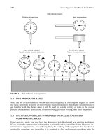
One way to accomplish this measurement is to perform the double radial method (refer to
Chapter 12). As shown in Figure 19.4, the dial indicator measurements can be taken on the
inside bore of a cylinder rather than capturing the measurements on the outside of a cylinder
(e.g., a shaft). Remember that you will have to compensate for the bracket sag that occurs at
both the near and far indicators. You also have to be aware of the fact that you are reading an
inside diameter and the sign (þ=À) of the measurement from the top to the bottom (or side
to side) will be opposite of what it would be if you were measuring the outside diameter.
View looking down the axis of rotation through clear shafts
FIGURE 19.1 View through the axis of rotation.
FIGURE 19.2 Motor and barrel.
Piotrowski / Shaft Alignment Handbook, Third Edition DK4322_C019 Final Proof page 620 26.9.2006 8:43pm
620 Shaft Alignment Handbook, Third Edition
For example, with the indicator set up to take a reading on the inside of the barrel, if the
indicator is zeroed at the top of the inside of the barrel then rotated to the bottom and the dial
indicator measured a þ20, the barrel appears to be ‘‘high’’ at that point. If instead, the indi-
cator was set up to take a reading on the outside of the barrel, if the indicator is zeroed
at the top of the outside of the barrel then rotated to the bottom, the dial indicator would
measure a À 20.
Figure 19.5 shows the dimensions and double radial measurements that were taken on the
motor and barrel. Figure 19.6 and Figure 19.7 show the side and top view alignment models.
Centerline of barrel
Centerline of rotation
Centerline of barrel is in line only
with the end of the motor shaft
FIGURE 19.3 Pure angular misalignment of motor shaft and barrel centerline.
0
50
10
40
20
30
+
_
10
40
20
30
0
50
10
40
20
30
+
_
10
40
20
30
Near indicator
Far indicator
0
50
10
40
20
30
+
_
10
40
20
30
0
50
10
40
20
30
+
_
10
40
20
30
Far indicator
Taking measurements on the outside of a cylinder
Taking measurements on the inside of a cylinder
r
o
t
a
t
e
Near indicator
FIGURE 19.4 Double radial method measuring outside and inside of cylinders.
Piotrowski / Shaft Alignment Handbook, Third Edition DK4322_C019 Final Proof page 621 26.9.2006 8:43pm
Bore Alignment 621
19.2 ALIGNING TWO HOLLOW CYLINDERS
Next, let us examine how you would align two hollow cylinders with each other. The
assumption is that the cylinders are perfectly straight (i.e., not bowed) and that the inside
diameters of the cylinders are consistent along the full length of both cylinders. Either cylinder
may, or may not, have the capability to rotate on an axis that is coincident with the centerline
of its bore. The measurement device that we will use for this basic procedure is an optical jig
transit (refer to Figure 6.11) held in position with an appropriate tripod or stand. The stand
must have a translation slide and a precision vertical lift. The jig transit must also have an
optical micrometer attached to the end of the telescope barrel (see Figure 6.15). The optical
micrometer can be positioned to translate either the horizontal or vertical crosshair by
rotating the micrometer through a 908 arc on the end of the telescope. The problem with
doing this is that you run the risk of inadvertently moving the scope to a different line of sight,
if you jar the scope when repositioning the optical micrometer. To reduce the need to rotate
the micrometer, a coordinate optical micrometer enables the user to measure target offsets
in both the vertical and horizontal planes without having to rotate a single axis micrometer
908 on the barrel of the telescope to capture both measurements as shown in Figure 19.8.
An additional tooling that is required are bore sighting targets and fixtures to position
and hold the sighting targets in the cylinders. Optical bore sighting targets are shown in
0
50
10
40
20
30
+
_
10
40
20
30
0
50
10
40
20
30
+
_
10
40
20
30
20 in.24 in.56 in.
5 in.
12 in.
View looking east
T
B
EW
0
T
B
EW
0
Near indicator
+10
Ϫ36
+16
Sag
compensated
readings
Ϫ20
+24Ϫ14
Far indicator
Near indicator
Far indicator
FIGURE 19.5 Motor and barrel dimensions and measurements taken on bore using the double
radial method.
Piotrowski / Shaft Alignment Handbook, Third Edition DK4322_C019 Final Proof page 622 26.9.2006 8:43pm
622 Shaft Alignment Handbook, Third Edition
Figure 19.8. These sighting targets are fabricated from nylon with an accurately painted
patternofpairedlinesset908 apart precisely positioned from the center of the target. A small
battery operated light source (e.g., a flashlight) can be used to illuminate the translucent
target from behind, as this target will usually be placed inside a dark cylinder. Other sighting
targets shown in Figure 19.9 are made out of thin wires or a pattern cut out of a thin piece
of metal, which will allow you to view objects behind the target acting as if they were
transparent. The see-through target is typically mounted as the nearest target to the jig transit
Up
Side view
Scale:
10 in. 20 mils
MotorBarrel
T
B
E
W
0
T
B
EW
0
Near indicator
+10
Ϫ36 +16
Sag
compensated
readings
Ϫ20
+24
Ϫ14
Far indicator
FIGURE 19.6 Side view alignment model of motor centerline and barrel centerline.
Scale: 10 in. 20 mils
East
Top view
MotorBarrel
T
B
EW
T
B
EW
Near indicator
0 +52 +380
Far indicator
FIGURE 19.7 Top view alignment model of motor centerline and barrel centerline.
Piotrowski / Shaft Alignment Handbook, Third Edition DK4322_C019 Final Proof page 623 26.9.2006 8:43pm
Bore Alignment 623
enabling visual sighting of targets down range without having to move the see-through
target from its position.
The sighting targets will be placed at different points in the center of the cylinder and they
do not have the capacity to automatically center themselves. Therefore a sighting target
FIGURE 19.8 Coordinate optical micrometer. (Courtesy of Brunson Instruments, Kansas City, MO.
With permission.)
FIGURE 19.9 Translucent bore sighting target. (Courtesy of Brunson Instruments, Kansas City, MO.
With permission.)
Piotrowski / Shaft Alignment Handbook, Third Edition DK4322_C019 Final Proof page 624 26.9.2006 8:43pm
624 Shaft Alignment Handbook, Third Edition