Handbook Of Shaft Alignment Episode 2 Part 10 pdf
Bạn đang xem bản rút gọn của tài liệu. Xem và tải ngay bản đầy đủ của tài liệu tại đây (837.43 KB, 30 trang )
16.18.2 DETERMINING THE DESIRED OFF-LINE SHAFT POSITIONS WHEN
USING THE MACHINE CASE TO BASEPLATE OR MACHINE CASE
TO
REMOTE REFERENCE POINT METHODS
If you employed one of the following techniques to measure OL2R movement, the data you
collected show how each end of the machinery moved from OL2R conditions (Figure 16.84
and Figure 16.85) .
Side view
Scale :
Measurement
points at or near
each bearing
Motor
Multistage pump
Motor Multistage pump
10 in.
10 mils
Observed amount of movement from OL2R conditions
view looking east for the lateral (sideways) movement
8 mils up
2 mils east
14 mils up
5 mils east
32 mils up
14 mils west
24 mils up
20 mils east
8 mils up
14 mils up
32 mils up
24 mils up
Desired off-line vertical shaft positions
Up
FIGURE 16.84 Example of a desired off-line side view (vertical) shaft position alignment model using
the machine case to baseplate or machine case to remote reference point methods.
Piotrowski / Shaft Alignment Handbook, Third Edition DK4322_C016 Final Proof page 540 6.10.2006 12:03am
540 Shaft Alignment Handbook, Third Edition
.
Calculating machine case thermal expansion using the strain equation
.
Inside micrometer–tooling ball–angle measurement devices
.
Proximity probes with water-cooled stands
.
Optical alignment equipment
Graph paper similar to what is used for the graphing or modeling techniques covered in
Chapter 8 can be used to show the desired off-line shaft positions. The graph centerline will
represent the final position of the shafts, which is often referred to as the ‘‘hot operating
position’’ or running shaft positions. If the machinery shafts move from OL2R conditions,
lines will be drawn on the graph paper to represent what position they should be in when off-
line, so that when they move during operation, they will come in line with each other (i.e., end
up on top of the graph centerline).
Along the graph centerline, mark where the OL2R measurements were taken at the inboard
and outboard ends of each piece of machinery. Other critical points such as the dial indicator
(or laser–detector) reading point locations and foot bolt points can be shown. Once the
desired off-line shaft positions are drawn, ‘‘shoot for’’ dial indicator readings can be deter-
mined for the shaft positions when off-line.
It should become apparent by this time that if you are using dial indicators and brackets
that have sag and that the shafts should not be in line with each other when off-line, you
should never want to ‘‘spin zeros’’ for the dial indicator readings.
East
Top view
Scale:
Motor Multistage pump
10 in.
10 mils
2 mils east
5 mils east
14 mils west
20 mils east
Desired off-line lateral shaft positions
FIGURE 16.85 Example of a desired off-line top view (lateral) shaft position alignment model using the
machine case to baseplate or machine case to remote reference point methods.
Piotrowski / Shaft Alignment Handbook, Third Edition DK4322_C016 Final Proof page 541 6.10.2006 12:03am
Measuring and Compensating for Off-Line 541
16.18.3 DETERMINING THE DESIRED OFF-LINE SHAFT POSITIONS WHEN USING
THE
MACHINE CASE TO MACHINE CASE METHODS
If you employed one of the following techniques to measure OL2R movement, the data you
collected show how one machine case moved with respect to the other machine case from
OL2R conditions:
.
Alignment bars or custom fixtures with proximity probes
.
Laser–detector systems with custom-fabricated brackets or special mounting systems
.
Ball–rod–tubing connector system
Graph paper similar to what is used for the graphing or modeling techniques covered in
Chapter 8 can be used to show the desired off-line shaft positions. The graph centerline will
represent the final position of the shafts, which is often referred to as the ‘‘hot operating
position’’ or running shaft positions. In these OL2R methods, it is not known how each
machine moved from OL2R conditions with respect to a fixed point in space (as opposed to
the previously covered methods which do). What is known is how one machine saw the
other machine move. Therefore, one of the two machine cases or shafts is used as a reference
shaft and its position is placed directly on top of the graph centerline. The other machine
case or shaft is then drawn on the graph paper to reflect how it moved with respect to the
reference shaft.
Along the graph centerline, mark where the OL2R measurements were taken at the inboard
and outboard ends of each piece of machinery. Other critical points such as the dial indicator
(or laser–detector) reading point locations and foot bolt points can be shown. Once the
desired off-line shaft positions are drawn, shoot for dial indicator readings can be determined
for the shaft positions when off-line.
If the alignment bar system was used to determine the machinery movement, the desired
off-line side view (vertical) shaft position alignment model setup might look like Figure 16.86.
A little bit of thought is going to have to be put forth to recall how the probes were positioned
when reading the targets and what decreasing or increasing gaps mean when setting up the
chart. It is easy to make a mistake here by misinterpreting the movement data, so it is wise to
make sure both the amount of movement and the direction of movement are correct and that
you have gone over the graph setup at least twice before running out and positioning
the machinery with shoot for readings that are wrong. Figure 16.87 shows how the desired
off-line side view (vertical) shaft position alignment model might look if you used a laser–
detector system with custom-fabricated brackets or generic mounting brackets or if you used
the BRTC system.
16.18.4 HOW TO DETERMINE THE ‘‘SHOOT FOR’’ OFF-LINE DIAL INDICATOR
READINGS (ALSO KNOWN AS ‘‘TARGET VALUES’’)
So far in this chapter, we have reviewed a number of methods to determine how machinery
will move from OL2R conditions. In addition, we have been able to take these data and plot
the information onto a graph showing where the shafts should be when the equipment is not
running. As you can see, if all of the shafts in the drive system do not move in unison with
each other (i.e., the same amount and in the same direction), the shaft centerlines should not
be collinear when off-line. Since the shafts should not be in line with each other when off-line,
what should the off-line alignment measurements be to insure the shafts are in the desired off-
line positions similar to what is shown in Figure 16.86 through Figure 16.88. What would the
Piotrowski / Shaft Alignment Handbook, Third Edition DK4322_C016 Final Proof page 542 6.10.2006 12:03am
542 Shaft Alignment Handbook, Third Edition
alignment readings be if you were using the reverse indicator method, face–rim, double radial,
shaft to coupling spool, or the face–face method?
16.18.4.1 Reverse Indicator Shoot for Dial Indicator Readings
If you will be using the reverse indicator method to align your machinery, apply the following
procedures to determine what the shoot for readings will be when aligning your machinery to
compensate for OL2R movement:
Motor Multistage pump
Side view
Scale:
Motor Multistage pump
10 in.
10 mils
Observed amount of proximity probe gap change from OL2R conditions
Vertical probe gap
increased by 12 mils
from OL2R
Desired off-line vertical shaft positions
Vertical probe gap
increased by 16 mils
from OL2R
Vertical probe gap increased
by 12 mils from OL2R
Vertical probe gap increased
by 16 mils from OL2R
Target bar attached
to this machine
Probe bar attached
to this machine
Up
FIGURE 16.86 Example of a desired off-line side view (vertical) shaft position alignment model using
the alignment bars or custom fixtures with proximity probes. The desired off-line top view (lateral) shaft
position alignment model is not shown.
Piotrowski / Shaft Alignment Handbook, Third Edition DK4322_C016 Final Proof page 543 6.10.2006 12:03am
Measuring and Compensating for Off-Line 543
1. Plot the desired off-line shaft positions of both the driver and driven units. Figure 16.89
shows a motor and a pump plotted in both the side and top views. The amount of
movement of these shafts are based on the data collected from any of the OL2R
measurement techniques explained in this chapter.
2. Based on the chosen scale factor from top to bottom on the chart, measure the A and B
gaps.
3. Determine whether the bottom readings taken on each shaft are positive or negative by
applying the following rules. Rules to determine the sign (þ)or(À) of the measurements:
a. If the actual centerline of a unit is toward the bottom of the graph with respect to a
projected centerline, the reading will be positive (þ).
Motor Multistage pump
Side view
Scale:
Motor Multistage pump
10 in.
10 mils
Motor defined as the
reference machine
Desired off-line vertical shaft positions
Pump defined as the
observed or target machine
Laser−detector system
observed that the inboard
end of the pump raised
upwards 20 mils
Laser−detector
Laser−detector
Laser−detector or prism
Laser−detector or prism
Laser−detector system
observed that the outboard
end of the pump raised
upwards 10 mils
Up
FIGURE 16.87 Example of a desired off-line side view (vertical) shaft position alignment model using a
laser–detector system with custom-fabricated brackets or special mounting systems. The desired off-line
top view (lateral) shaft position alignment model is not shown.
Piotrowski / Shaft Alignment Handbook, Third Edition DK4322_C016 Final Proof page 544 6.10.2006 12:03am
544 Shaft Alignment Handbook, Third Edition
b. If the actual centerline of a unit is toward the top of the graph with respect to a projected
centerline, the reading will be negative (À).
In other words, try to visualize what is going to happen to the dial indicator stem as it
traverses circumferentially from top to bottom on the shaft of each machine. Is it going to
move outward (negative) or inward (positive)? In Figure 16.89, the side view shows that
the motor centerline appears to be higher from the vantage point of the pump, therefore the
dial indicator stem will move outward as it rotates to the bottom of the pump shaft producing
Motor Multistage pump
Side view
Scale:
Motor Multistage pump
10 in.
10 mils
Observed amount of proximity probe gap change from OL2R conditions
Vertical probe gap
decreased by 4 mils
from OL2R
Desired off-line vertical shaft positions
Vertical probe gap
increased by 5 mils
from OL2R
Vertical probe gap decreased by
4 mils from OL2R
Vertical probe gap increased
by 5 mils from OL2R
Tubing connector
Ball−rod
Ball−rod
Prox probes
Up
FIGURE 16.88 Example of a desired off-line side view (vertical) shaft position alignment model using a
ball–rod–tubing connector system. The desired off-line top view (lateral) shaft position alignment model
is not shown.
Piotrowski / Shaft Alignment Handbook, Third Edition DK4322_C016 Final Proof page 545 6.10.2006 12:03am
Measuring and Compensating for Off-Line 545
Up
Side view
Scale :
Motor
Multistage pump
Motor Multistage pump
10 in.
10 mils
Desired off-line vertical pump shaft position
Desired off-line vertical motor shaft position
Reverse indicator method
East
Top view
Scale:
Motor Multistage pump
10 in.
10 mils
Desired off-line lateral pump shaft position
Desired off-line lateral motor shaft position
AB
C
D
Where the dial indicator readings will be taken on the motor
shaft with the bracket attached to the pump shaft
A and B indicate the distances between
the two centerlines of rotation where
the readings will be taken when
looking in the side view
C and D indicate the distances
between the two centerlines of
rotation where the readings will be
taken when looking in the top view
Where the dial indicator readings will be taken on the pump
shaft with the bracket attached to the motor shaft
0
50
10
40
20
30
+
_
10
40
20
30
0
50
10
40
20
30
+
_
10
40
20
30
0
50
10
40
20
30
+
_
10
40
20
30
0
50
10
40
20
30
+
_
10
40
20
30
FIGURE 16.89 Example of desired off-line side and top view alignment models of a motor and a pump
to calculate the shoot for reverse indicator measurements.
Piotrowski / Shaft Alignment Handbook, Third Edition DK4322_C016 Final Proof page 546 6.10.2006 12:03am
546 Shaft Alignment Handbook, Third Edition
a negative reading. From the vantage point of the motor, the dial indicator stem will move
inward as it rotates to the bottom of the pump shaft producing a positive reading.
4. Based on the chosen scale factor from top to bottom on the chart, record the C and D
gaps as shown in Figure 16.89 for the top view. Remember, you should always zero your
indicator on the side that is pointing toward the top of your graph paper, in this case, it
is east. Apply the same logic explained in step 3 to determine if the reading will be
positive or negative.
5. Apply the appropriate gaps at A, B, C,andD into the equations shown in Figure 16.90
and solve. The shoot for reverse indicator readings solution for the desired off-line shaft
positions in the side and top views for Figure 16.89 is shown in Figure 16.90 assuming
that there is 10 mils of bracket sag.
((±A) − (±C)) + sag/2
(2 (±A)) + sag
+ (±C)
(± A) − (±C)
2
2
Driver
+ sag/2
(2 (± B)) + sag
((±B) − (±D)) + sag/2
+ (±D)
(±B) − (±D)
2
2
Driven
+ sag/2
0
Top
Bottom
East West
0
Top
Bottom
East
West
Motor
Pump
0
Top
Bottom
East
West
0
Top
Bottom
East
West
−28
+17−45
+40
+41
−1
sag = 10 mils
((−19) − (+31)) + 5
(2 (−19)) + 10
+ (+31)
(−19) − (+31)
2
2
Motor
+ 5
((+15) − (−21)) + 5
(2 (+15)) + 10
+ (−21)
(+15) − (− 21)
2
2
Pump
+ 5
0
Top
Bottom
East
West
0
Top
Bottom
East
West
(
((
(
(((
((
(
((
)
)
)
))
)))
)
)
)
)
FIGURE 16.90 General equations to calculate the shoot for reverse indicator measurements and a
sample calculation based on the shaft positions shown in Figure 16.89.
Piotrowski / Shaft Alignment Handbook, Third Edition DK4322_C016 Final Proof page 547 6.10.2006 12:03am
Measuring and Compensating for Off-Line 547
16.18.4.2 Face–Rim Shoot for Dial Indicator Readings
Figure 16.91 shows the desired off-line shaft positions of a motor and a pump in both the side
and top views. In this particular case, ‘‘front side’’ face readings were taken on the pump shaft
and the T-bar overlay was used to model the desired shaft positions. Similar to the procedure
for reverse indicator, measure the gaps A, B, FV, and FL. Figure 16.92 shows the general
equations needed to solve for the shoot for face–rim readings as well as the specific face–rim
shoot for readings you would obtain for the desired off-line shaft positions shown in Figure
16.91.
16.18.4.3 Double Radial Shoot for Dial Indicator Readings
Figure 16.93 shows the desired off-line shaft positions of a motor and a fan in both the side
and top views. Similar to the above procedure for reverse indicator, measure the gaps A, B, C,
and D. Figure 16.94 shows the general equations needed to solve for the shoot for double
radial readings as well as the specific double radial shoot for readings you would obtain for
the desired off-line shaft positions shown in Figure 16.93.
16.18.4.4 Shaft to Coupling Spool Shoot for Dial Indicator Readings
Figure 16.95 shows the desired off-line shaft positions of a gear and a motor in both
the side and top views. Similar to the procedure for reverse indicator, measure the gaps
A, B, C,andD. Figure 16.96 shows the general equations needed to solve for the shoot
for shaft to coupling spool readings as well as the specific shaft to coupling spool
shoot for readings you would obtain for the desired off-line shaft positions shown in Figure
16.95.
16.18.4.5 Face–Face Shoot for Dial Indicator Readings
Figure 16.97 shows the desired off-line shaft positions of a motor and a calender roll in both
the side and top views. In this particular case, ‘‘front side’’ face readings were taken from
both the motor to the drive shaft (also known as coupling spool) and from the calender roll
shaft to the drive shaft. The T-bar overlay was again used to model the desired shaft
positions. Similar to the procedure for face–rim, measure the gaps FA, FB, FC, and FD.
Figure 16.98 shows the general equations needed to solve for the shoot for face–face readings
as well as the specific face–face shoot for readings you would obtain for the desired off-line
shaft positions shown in Figure 16.97.
16.19 ALIGNING SHAFTS FOR RUNNING CONDITIONS (ALSO KNOWN
AS RUNNING ALIGNMENT OR ‘‘HOT OPERATING ALIGNMENT’’)
The graphing or modeling techniques shown in Chapter 8 illustrated how to align two shafts
with each other to insure they were collinear when off-line. If you do not want the shafts to be
collinear when they are not running but want them to be in a specific desired off-line position
is similar to what is shown in Figure 16.89 through Figure 16.98.
The trick to offset aligning rotating machinery shafts is to shift the position of the shafts to
where they will be when they are running and align the running shaft positions. Once the
shafts have been shifted to their running positions, the vertical and lateral movement restric-
tions can be superimposed onto the model, and the overlay line can then be used to determine
the appropriate vertical and lateral repositioning movements required to put the shafts in the
desired off-line positions.
Piotrowski / Shaft Alignment Handbook, Third Edition DK4322_C016 Final Proof page 548 6.10.2006 12:03am
548 Shaft Alignment Handbook, Third Edition
Up
Side view
Scale:
Motor
Multistage pump
Motor Multistage pump
10 in. or 10 mils
Desired off-line vertical pump shaft position
Desired off-line vertical motor shaft position
Face–rim method
East
Top view
Scale:
Motor Multistage pump
Desired off-line lateral pump shaft position
Desired off-line lateral motor shaft position
FV
B
D
A indicates the distances between the
two centerlines of rotation where the
rim reading will be taken when looking
in the side view
Where the dial indicator readings will be taken on the pump shaft
FL
A
D
FV is the face reading taken on diameter D
when looking in the side view
B indicates the distances between the
two centerlines of rotation where the
rim reading will be taken when looking
in the top view
FL is the face reading taken on diameter D
when looking in the top view
10 in. or
10 mils
10 in. or 10 mils
10 in. or
10 mils
0
50
10
40
20
30
+
_
10
40
20
30
0
50
10
40
20
30
+
_
10
40
20
30
0
50
10
40
20
30
+
_
10
40
20
30
0
50
10
40
20
30
+
_
10
40
20
30
FIGURE 16.91 Example of desired off-line side and top view alignment models of a motor and a pump
to calculate the shoot for face–rim measurements.
Piotrowski / Shaft Alignment Handbook, Third Edition DK4322_C016 Final Proof page 549 6.10.2006 12:03am
Measuring and Compensating for Off-Line 549
East West
Top
Bottom
0
+42
+40
−2−2.5 +2.5
0
0
Rim sag = 10 mils
Face sag = 2 mils
((+15) − (−22)) + 10/2
(2 (+15)) + 10
East West
Top
Bottom
0
0
(−2) + 2
((−2/2) − (+5/2)) + 2/2
+ (−22)
(+15) − (−22)
2
2
+ 10/2
+ (+5/2)
(−2/2) − (+5/2)
2
2
+ 2/2
((±A) − (±B)) + rim sag/2
(2 (±A)) + rim sag
East West
Top
Bottom
0
0
(±FV) + face sag
((±FV/2) − (±FL/2)) + face sag/2
+ (±B)
(±A) − (±B)
2
2
+ rim sag/2
+ (±FL/2)
(±FV/2) − (±FL/2)
2
2
+ face sag/2
(
((
(((
(
((
)
)
))
(((
)))
)
))
)
)
FIGURE 16.92 General equations to calculate the shoot for face–rim measurements and a sample
calculation based on the shaft positions shown in Figure 16.91.
Piotrowski / Shaft Alignment Handbook, Third Edition DK4322_C016 Final Proof page 550 6.10.2006 12:03am
550 Shaft Alignment Handbook, Third Edition
Up
Side view
Scale:
Motor Fan
10 in.
10 mils
Desired off-line vertical fan shaft position
Desired off-line vertical motor shaft position
Double radial method
East
Top view
Scale:
Motor Fan
10 in.
10 mils
Desired off-line lateral fan shaft position
Desired off-line lateral motor shaft position
AB
C
D
Where the dial indicator readings will be taken on the fan
shaft at the near indicator location
A and B indicate the distances between
the two centerlines of rotation where
the readings will be taken when
looking in the side view
C and D indicate the distances
between the two centerlines of
rotation where the readings will be
taken when looking in the top view
Where the dial indicator readings will be taken on the fan
shaft at the far indicator location
Motor
Fan
Near indicator
Far indicator
0
50
10
40
20
30
+
_
10
40
20
30
0
50
10
40
20
30
+
_
10
40
20
30
0
50
10
40
20
30
+
_
10
40
20
30
0
50
10
40
20
30
+
_
10
40
20
30
0
50
10
40
20
30
+
_
10
40
20
30
0
50
10
40
20
30
+
_
10
40
20
30
FIGURE 16.93 Example of desired off-line side and top view alignment models of a motor and a fan to
calculate the shoot for double radial measurements.
Piotrowski / Shaft Alignment Handbook, Third Edition DK4322_C016 Final Proof page 551 6.10.2006 12:03am
Measuring and Compensating for Off-Line 551
Figure 16.99 shows the type of information that needs to be gathered on a two element
drive train before final alignment.
In summary:
.
Gather specific information on the drive train such as how the machinery will move from
OL2R conditions, piping fit up problems, the total shim thickness that exists under the
machinery feet, how far can each unit be moved sideways at the feet, what positions the
shafts should be in when off-line, and what are the ‘‘shoot for’’ readings.
.
What positions are the shafts actually in when off-line?
.
How will the movement restrictions affect the final chosen alignment line?
Near sag = 10 mils
Far sag = 16 mils
0
Top
Bottom
East
West
0
Top
Bottom
East
West
+44
−6
+50
+44
+1+43
Near indicator
Far indicator
((+17) − (−28)) + 5
(2 (+17)) + 10
+ (−28)
(+17) − (−28)
2
2
+ 5
((+14) − (−21)) + 8
(2 (+14)) + 16
+ (−21)
(+14) − (−21)
2
2
+ 8
0
Top
Bottom
East
West
0
Top
Bottom
East
West
Near indicator
Far indicator
((±A) − (±C)) + near sag/2
(2 (±A)) + near sag
+ (±C)
(±A) − (±C)
2
2
Near indicator
+ near sag/2
((±B) − (±D)) + far sag/2
(2 (±B)) + far sag
+ (±
D
)
(±B) − (±D)
2
2
Far indicator
+ far sag/2
0
Top
Bottom
East West
0
Top
Bottom
East
West
(
(
(
(((
(
(
(
(
((
)
)
)
)))
))
))
))
FIGURE 16.94 General equations to calculate the shoot for double radial measurements and a sample
calculation based on the shaft positions shown in Figure 16.93.
Piotrowski / Shaft Alignment Handbook, Third Edition DK4322_C016 Final Proof page 552 6.10.2006 12:03am
552 Shaft Alignment Handbook, Third Edition
Up
Side view
Scale:
Motor
Gear
10 in.
10 mils
Desired off-line vertical motor shaft position
Desired off-line vertical gear shaft position
Shaft to coupling spool method
East
Top view
Scale:
10 in.
10 mils
Desired off-line lateral motor shaft position
Desired off-line lateral gear shaft position
A
B
C
Where the dial indicator
readings will be taken
from the fan shaft to the
coupling spool
C and D indicate the distances
between each centerline of rotation
where the readings will be taken on
the coupling spool when looking in
the top view
Motor
Gear
Where the dial indicator
readings will be taken
from the motor shaft to
the coupling spool
Coupling flex point
Coupling flex point
D
Motor
Gear
A and B indicate the distances
between each centerline of rotation
where the readings will be taken on
the coupling spool when looking in
the side view
0
50
10
40
20
30
+
_
10
40
20
30
0
50
10
40
20
30
+
_
10
40
20
30
0
50
10
40
20
30
+
_
10
40
20
30
0
50
10
40
20
30
+
_
10
40
20
30
FIGURE 16.95 Example of desired off-line side and top view alignment models of a gear and a motor to
calculate the shoot for shaft to coupling spool measurements.
Piotrowski / Shaft Alignment Handbook, Third Edition DK4322_C016 Final Proof page 553 6.10.2006 12:03am
Measuring and Compensating for Off-Line 553
Figure 16.100 shows the side and top view alignment models for the motor and multistage
pump. The models show both the actual off-line shaft positions and the running shaft
positions. To better clarify the alignment condition, Figure 16.101 shows only the running
shaft positions. Superimposed on the side view, the total shim thickness that exists under each
of the bolting planes have been shown and hence we know how far down each shaft could be
moved. Superimposed on the top view, the lateral movement restrictions at each of the
bolting planes have been shown and so we know how far to the east or west each shaft
could be moved without getting bolt bound. Figure 16.101 also shows possible solutions in
the side and top views by superimposing an overlay line. Bear in mind that there are other
possible solutions besides the ones shown.
0
Top
Bottom
East
West
0
Top
Bottom
East
West
+24
+25
−1
−22
−20
−2
Gear to spool
Motor to spool
sag = 10 mils at both brackets
((+7) − (+13)) + 5
(2 (+7)) + 10
+ (+13)
(+7) − (+13)
2
2
+ 5
((−16) − (+9)) + 5
(2 (−16)) + 10
+ (+9)
(−16) − (+9)
2
2
+ 5
0
Top
Bottom
East
West
0
Top
Bottom
East
West
Gear to spool
Motor to spool
((±A) − (±C)) + sag/2
(2 (±A)) + sag
+ (±C)
(±A) − (±C)
2
2
Gear to spool
+ sag/2
((±B) − (±D)) + sag/2
(2 (±B)) + sag
+ (±D)
(±B) − (±D)
2
2
Motor to spool
+ sag/2
0
Top
Bottom
East West
0
Top
Bottom
East
West
(
(
(
(((
((
((
(( ) )
)
)))
)))
))
)
FIGURE 16.96 General equations to calculate the shoot for shaft to coupling spool measurements and a
sample calculation based on the shaft positions shown in Figure 16.95.
Piotrowski / Shaft Alignment Handbook, Third Edition DK4322_C016 Final Proof page 554 6.10.2006 12:03am
554 Shaft Alignment Handbook, Third Edition
Up
Side view
Scale :
Motor
10 in. or 10 mils
Desired off-line vertical calender
roll position
Desired off-line vertical motor shaft position
Face–face Method
East
Top view
Scale :
Motor
Desired off-line lateral calender roll position
Desired off-line lateral motor shaft position
FA
D
FB is the face reading taken
from the calender roll on
diameter D when looking in
the side view
10 in. or
10 mils
10 in. or 10 mils
10 in. or
10 mils
Motor
Calender roll
Drive shaft
Calender roll
Calender roll
D
FA is the face reading
taken from the motor on
diameter D when looking in
the side view
Coupling flex point
Coupling flex point
FB
FC
FD
FD is the face reading taken
from the calender roll on
diameter D when looking in
the top view
FC is the face reading
taken from the motor on
diameter D when looking in
the top view
FIGURE 16.97 Example of desired off-line side and top view alignment models of a motor and a
calender roll to calculate the shoot for face–face measurements.
Piotrowski / Shaft Alignment Handbook, Third Edition DK4322_C016 Final Proof page 555 6.10.2006 12:03am
Measuring and Compensating for Off-Line 555
−2.5
East West
Top
Bottom
0
Calender roll to spool
Motor to spool
East West
Top
Bottom
0
0
+1.5
−1
+4 +2
Face sag = 2 mils
East West
Top
Bottom
0
(−3) + 2
((−3/2) − (+4/2)) + 2/2
(((
+ (+4/2)
(−3/2) − (+4/2)
2
2
+ 2/2
))
)
Calender roll to spool
Motor to spool
East West
Top
Bottom
0
(+4) + 2
((+4/2) − (−2/2)) + 2/2
(((
+ (−2/2)
(+4/2) − (−2/2)
2
2
+ 2/2
)))
East West
Top
Bottom
0
(±FA) + face sag
((±FA/2) − (±FC/2)) + face sag/2
(((
+ (±FC/2)
(±FA/2) − (±FC/2)
2
2
+ face sag/2
)))
Calender roll to spool
Motor to spool
East West
Top
Bottom
0
(±FB) + face sag
((±FB/2) − (±FD/2)) + face sag/2
(((
+ (±FD/2)
(±FB/2) – (± FD/2)
2
2
+ face sag/2
)))
FIGURE 16.98 General equations to calculate the shoot for face–face measurements and a sample
calculation based on the shaft positions shown in Figure 16.97.
Piotrowski / Shaft Alignment Handbook, Third Edition DK4322_C016 Final Proof page 556 6.10.2006 12:03am
556 Shaft Alignment Handbook, Third Edition
Motor
Multistage pump
0
50
10
40
20
30
+
_
10
40
20
30
0
50
10
40
20
30
+
_
10
40
20
30
Motor
0
Top
Bottom
East West
0
Top
Bottom
East
West
+20
−16+36
−50
+30−80
8 mils up
2 mils east
14 mils up
5 mils east
32 mils up
14 mils west
24 mils up
20 mils east
OL2R measurement location
Foot bolt
Shaft measurement location
Shaft measurement location
OL2R measurement location
Foot bolt
Foot bolt
Foot bolt
OL2R measurement location
OL2R measurement location
Foot bolt allowable movement:
50 mils of shims could be removed
80 mils east to bolt bind
40 mils west to bolt bind
Foot bolt allowable movement:
20 mils of shims could be removed
30 mils east to bolt bind
90 mils west to bolt bind
Foot bolt allowable movement:
100 mils of shims could be removed
0 mils east to bolt bind
120 mils west to bolt bind
Foot bolt allowable movement:
75 mils of shims could be removed
50 mils east to bolt bind
70 mils west to bolt bind
Pump
Actual
field
readings
0
Top
Bottom
East
West
0
Top
Bottom
East
West
Sag
compensated
readings
0
Top
Bottom
East
West
Bracket
sag
−10
−5−5
−40
+35−75
+30
−11+41
Pump
0
Top
Bottom
East West
+40
−1
+41
Motor
0
Top
Bottom
East West
−28
+17−
45
Shoot for
readings
•
•
•
• Soft foot has been corrected
• Acceptable runout on pump
• Bearings and seals in good
9 in. 40 in. 5 in.
3 in.
20 in.
2 in.
7 in. 40 in. 6 in.
Soft foot has been corrected
Acceptable runout on motor
shaft and coupling
Bearings and seals in good
condition
shaft and coupling
condition
FIGURE 16.99 Typical information to be gathered on a two element drive train before final alignment.
Piotrowski / Shaft Alignment Handbook, Third Edition DK4322_C016 Final Proof page 557 6.10.2006 12:03am
Measuring and Compensating for Off-Line 557
Up
Side view
Scale :
Motor Multistage pump
10 in.
10 mils
8 mils up
14 mils up
32 mils up
24 mils up
Off-line motor shaft position
Off-line pump shaft position
Running motor shaft position
Running pump shaft position
Top view
Scale :
Motor Multistage pump
10 in.
30 mils
Off-line motor shaft position
Off-line pump shaft position
Running motor shaft position
Running pump shaft position
East
2 mils east
5 mils east
14 mils west
20 mils east
0
50
10
40
20
30
+
_
10
40
20
30
0
50
10
40
20
30
+
_
10
40
20
30
0
50
10
40
20
30
+
_
10
40
20
30
0
50
10
40
20
30
+
_
10
40
20
30
FIGURE 16.100 Side and top view alignment models for the motor and multistage pump shown in
Figure 16.99.
Piotrowski / Shaft Alignment Handbook, Third Edition DK4322_C016 Final Proof page 558 6.10.2006 12:03am
558 Shaft Alignment Handbook, Third Edition
Top view
Scale:
Motor Multistage pump
10 in.
30 mils
Running motor
shaft position
Running pump
shaft position
East
Lateral movement restriction points
Pivot here
Move 12 mils west
Move 42 mils west
Pivot here
0
50
10
40
20
30
+
_
10
40
20
30
0
50
10
40
20
30
+
_
10
40
20
30
Up
Side view
Scale:
Motor Multistage pump
10 in.
20 mils
Running motor shaft position
Running pump shaft position
Baseplate restriction points
Lower 33 mils down
Pivot here
Pivot here
Lower 25 mils down
Note: Always be aware of your scale factors!
0
50
10
40
20
30
+
_
10
40
20
30
0
50
10
40
20
30
+
_
10
40
20
30
FIGURE 16.101 Side and top view alignment models for the motor and multistage pump showing the
running shaft positions, boundary restrictions, and suggested possible alignment correction moves.
Piotrowski / Shaft Alignment Handbook, Third Edition DK4322_C016 Final Proof page 559 6.10.2006 12:03am
Measuring and Compensating for Off-Line 559
As mentioned at the beginning of this chapter, very few people conduct OL2R machinery
movement surveys. Assuming that your rotating machinery does not move from OL2R
conditions is nothing more than burying your head in the sand and pretending that everything
will automatically align itself when operating. All of this data gathering, modeling, and
calculations seem quite tedious, but in many cases this extra effort may spell the difference
between machinery that seems to be plagued with problems or equipment that operates
successfully for long periods of time.
BIBLIOGRAPHY
Alignment=Auto Collimating Laser System 71-2615—Operating Manual, Manual No. 71-1000-4,
Keuffel and Esser Co., Morristown, NJ, 1982.
Applied Infrared Photography, Publication No. M-28, Eastman Kodak Co., Rochester, NY, May 1981.
Barnes, E.F., Optical alignment case histories, Hydrocarbon Processing, January 1971, 80–82.
Baumann, N.P., Tipping, W.E., Jr., Vibration Reduction Techniques for High-Speed Rotating Equip-
ment, A.S.M.E., Paper No. 65-WA=PWR-3, August 5, 1965.
Baumeister, T., Avallone, E.A., Baumeister, T., III, Mark’s Standard Handbook for Mechanical Engin-
eers, 8th ed., McGraw-Hill, New York, NY, 1978.
Blubaugh, R.L., Watts, H.J., Aligning rotating equipment, Chemical Engineering Progress, April 1969,
44–46.
Campbell, A.J., Optical alignment saves equipment downtime, Oil and Gas Journal, November 24, 1975.
Dodd, V.R., Shaft alignment monitoring cuts costs, Oil and Gas Journal, September 25, 1972, 91–96.
Dodd, V.R., Total Alignment, The Petroleum Publishing Co., Tulsa, Okla, 1975.
Essinger, J.N., Hot alignment too complicated? Hydrocarbon Processing, January 1974, 99–101.
Hanold, J., Application of Optical Equipment for Installing and Checking Large Machinery, A.S.M.E.,
Paper No. 61-PET-26, August 9, 1961.
Jackson, C., Alignment with Proximity Probes, A.S.M.E., Paper No. 68-PET-25, September 26, 1968.
Jackson, C., Successful shaft—hot alignment, Hydrocarbon Processing, January 1969.
Jackson, C., How to align barrel-type centrifugal compressors, Hydrocarbon Processing, September
1971, 189–194.
Jackson, C., The Practical Vibration Primer, Gulf Publishing Co., Houston, TX, 1979.
Kissam, P., Optical Tooling for Precise Manufacturing and Alignment, McGraw-Hill, New York, 1962.
Koenig, E., Align machinery by optical measurement, Plant Engineering, May 1964, 140–143.
Lukacs, N., Proximity Probe Applications for Troubleshooting Rotating Equipment Problems, I.S.A.
Paper No. 72–627, 1972.
Mager, M., Miller, R., Permalign Movement Exercise #15 Joy Air Compressor, Service Report Owens
Corning Fiberglas, Kansas City, MO, October 1989.
McGrae, Optical Tooling in Industry, Hayden Book Co., New York, 1964.
Mitchell, J.S., Optical Alignment—An Onstream Method to Determine the Operating Misalignment of
Turbomachinery Couplings, Dow Industrial Service, June 1972.
Mitchell, J.W., What is optical alignment? in: Proceedings—Third Turbomachinery Symposium, Gas
Turbine Labs, Texas A&M University, College Station, TX, 1974, pp. 17–23.
Murray, M., Measuring alignment thermal growth: what works and what doesn’t, in: Proceedings Pump
Users Expo ’98, Cincinnati, Ohio, October 28–31, 1998, Sponsored by Pumps and Systems
Magazine.
Murray, M., Shaft Alignment System, U.S. Patent No. 4,928,401, May 29, 1990 (Vernier–Strobe
System).
Murray, M., Laser Mount Assembly and Method, U.S. Patent No. 5,077,905, January 7, 1992 (PIBZLT
Mounts).
Nelson, C.A., Orderly steps simplify coupling alignment, Plant Engineering, June 1967, 176–178.
Norda, T., Use infrared scanning to find equipment hot spots, Hydrocarbon Processing, January 1977,
109–110.
O’Kelley, J.F., Optical shaft elevation measuring, Power Engineering, October 1969, 36–37.
Piotrowski / Shaft Alignment Handbook, Third Edition DK4322_C016 Final Proof page 560 6.10.2006 12:03am
560 Shaft Alignment Handbook, Third Edition
Optical Alignment Manual, No. 71-1000, Keuffel and Esser Co., Morristown, NJ, 1969.
Optical Alignment—A Maintenance Service to Reduce Your Machinery Downtime, Bulletin No. 371-
5000GP, Dresser Machinery Group, Dresser Industries, Houston, TX, 1969.
Personal correspondence with Malcolm Murray. December 2004.
The K&E Optical Leveling Kit and How to Use It, Bulletin No. T66-91222-66CT-3, Keuffel and Esser
Co., Morristown, NJ, 1976.
VanLaningham, F.L., Distortion of speed changer housings and resulting gear failures, in: Proceed-
ings—Fifth Turbomachinery Symposium, Gas Turbine Labs, Texas A&M University, College
Station, TX, October 1976, pp. 7–13.
Yarbrough, C.T., Optical checks put plant in line for low-maintenance future, Iron Age, January 20,
1960.
Yarbrough, C.T., Shaft alignment analysis prevents shaft and bearing failures, Westinghouse Engineer,
May 1966.
Yarbrough, C.T., Extracting the lemon from a large drag line, in: Open Pit Mining Association 27th
Annual Meeting, June 1971.
Piotrowski / Shaft Alignment Handbook, Third Edition DK4322_C016 Final Proof page 561 6.10.2006 12:03am
Measuring and Compensating for Off-Line 561
Piotrowski / Shaft Alignment Handbook, Third Edition DK4322_C016 Final Proof page 562 6.10.2006 12:03am
17
Aligning Multiple-Element
Drive Systems
The majority of rotating machinery drive systems in the world consists of two separate
machines mounted on a common base. For example, there are many electric motors driving
pumps and fans in virtually every industrial plant around the globe. If life were only that
simple, this book might have ended here. But real life is never that easy.
There are a considerable number of rotating machinery drive systems where there are three
or more machines coupled together to form what is commonly referred to as a drive ‘‘train.’’
Some examples of typical drive trains are as follows:
.
Motor–gear–pump systems
.
Motor–gear–compressor systems
.
High-pressure steam turbines–Intermediate-pressure steam turbines–Low-pressure steam
turbines–generators–exciter (HP–IP–LP–Generator systems)
.
Motor–generator–generator–generator systems (sometimes called MG sets)
.
Steam turbine–Gas Turbine–Gear–Low stage compressor–Gear–High stage compressor
(commonly found in refining and chemical industries)
.
Drive motor–clutch–gear–pinion–brake–right-angled gear–clutch–slow-speed turning
motor (commonly found in cement plants on kiln or ball mill drives)
.
Rack and pinion gear set–pinion drive shaft–right-angled gear–motor–pinion drive shaft–
rack and pinion gear set (found in automotive industries at vehicle assembly plants on
‘‘body drop’’ overhead cranes and various other industries having cranes that translate in
two directions)
The variation and mixture of rotating machinery drive systems in industry is as diverse as one
could possibly imagine. These machine cases can be horizontally mounted and coupled end-
to-end like a railroad train or they can be arranged at a right angle and some even have been
set up in a U-shaped or zigzag configuration.
In virtually every case, these drive trains are very expensive and frequently the heart and
soul of the operation of the plant. Some multiple-element drive trains fall in the small
horsepower range (10–500 hp) but there are a large percentage of these drive trains that are
500–50,000 hp costing millions of dollars. Consequentially, they are the most critical pieces of
machinery in the operation and the ones that seem to get everyone very nervous when
something goes wrong. Sometimes, small problems with these drive trains turn out to be
just minor distractions but when big problems occur, these systems turn out to be absolute
nightmares for the people involved in correcting the malady. Most people would just as soon
have pleasant dreams than nightmares, so a lot of effort is expended toward getting the
situation fixed correctly so that major problems occur infrequently.
Piotrowski / Shaft Alignment Handbook, Third Edition DK4322_C017 Final Proof page 563 26.9.2006 8:41pm
563
It is highly recommended that you become very adept at aligning two-element drive systems
before you try to tackle a multiple-element drive train. Every shred of knowledge you have
gained in your alignment experiences will be tested to your limits when one of these systems
has to be installed or completely rebuilt.
17.1 MULTIPLE-ELEMENT DRIVE TRAIN ALIGNMENT LAWS
Below are some suggestions and guidelines that may help in successfully aligning a multiple-
element drive system:
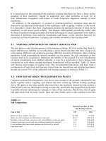
FIGURE 17.1 Motor–gear–blower drive system.
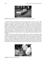
FIGURE 17.2 Motor–fluid drive–pump drive system.
Piotrowski / Shaft Alignment Handbook, Third Edition DK4322_C017 Final Proof page 564 26.9.2006 8:41pm
564 Shaft Alignment Handbook, Third Edition