Handbook of Corrosion Engineering Episode 2 Part 8 doc
Bạn đang xem bản rút gọn của tài liệu. Xem và tải ngay bản đầy đủ của tài liệu tại đây (276.79 KB, 25 trang )
833
Corrosion Inhibitors
10.1 Introduction 833
10.2 Classification of Inhibitors 834
10.2.1 Passivating (anodic) 836
10.2.2 Cathodic 837
10.2.3 Organic 837
10.2.4 Precipitation inhibitors 837
10.2.5 Volatile corrosion inhibitors 838
10.3 Corrosion Inhibition Mechanism 838
10.3.1 Inhibitors for acid solutions 839
10.3.2 Inhibitors in near-neutral solutions 845
10.3.3 Inhibitors for oil and gas systems 851
10.3.4 Atmospheric and gaseous corrosion 857
10.4 Selection of an Inhibitor System 860
References 861
10.1 Introduction
The use of chemical inhibitors to decrease the rate of corrosion
processes is quite varied. In the oil extraction and processing indus-
tries, inhibitors have always been considered to be the first line of
defense against corrosion. A great number of scientific studies have
been devoted to the subject of corrosion inhibitors. However, most of
what is known has grown from trial and error experiments, both in the
laboratories and in the field. Rules, equations, and theories to guide
inhibitor development or use are very limited.
By definition, a corrosion inhibitor is a chemical substance that, when
added in small concentration to an environment, effectively decreases
the corrosion rate. The efficiency of an inhibitor can be expressed by a
measure of this improvement:
Chapter
10
0765162_Ch10_Roberge 9/1/99 6:15 Page 833
Corrosion Inhibitors 835
TABLE 10.1 Some Corrosive Systems and the Inhibitors Used to Protect Them
System Inhibitor Metals Concentration
Acids
HCl Ethylaniline Fe 0.5%
MBT
*
1%
Pyridine ϩ phenylhydrazine 0.5% ϩ 0.5%
Rosin amine ϩ ethylene oxide 0.2%
H
2
SO
4
Phenylacridine 0.5%
H
3
PO
4
NaI 200 ppm
Others Thiourea 1%
Sulfonated castor oil 0.5–1.0%
As
2
O
3
0.5%
Na
3
AsO
4
0.5%
Water
Potable Ca(HCO
3
)
2
Steel, cast iron 10 ppm
Polyphosphate Fe, Zn, Cu, Al 5–10 ppm
Ca(OH)
2
Fe, Zn, Cu 10 ppm
Na
2
SiO
3
10–20 ppm
Cooling Ca(HCO
3
)
2
Steel, cast iron 10 ppm
Na
2
CrO
4
Fe, Zn, Cu 0.1%
NaNO
2
Fe 0.05%
NaH
2
PO
4
1%
Morpholine 0.2%
Boilers NaH
2
PO
4
Fe, Zn, Cu 10 ppm
Polyphosphate 10 ppm
Morpholine Fe Variable
Hydrazine O
2
scavenger
Ammonia Neutralizer
Octadecylamine Variable
Engine coolants Na
2
CrO
4
Fe, Pb, Cu, Zn 0.1–1%
NaNO
2
Fe 0.1–1%
Borax 1%
Glycol/water Borax ϩ MBT
*
All 1% ϩ 0.1%
Oil field brines Na
2
SiO
3
Fe 0.01%
Quaternaries 10–25 ppm
Imidazoline 10–25 ppm
Seawater Na
2
SiO
3
Zn 10 ppm
NaNO
2
Fe 0.5%
Ca(HCO
3
)
2
All pH dependent
NaH
2
PO
4
ϩ NaNO
2
Fe 10 ppm ϩ 0.5%
*MBT ϭ mercaptobenzotriazole.
0765162_Ch10_Roberge 9/1/99 6:15 Page 835
indicates that inhibitor adsorption on metals is influenced by the fol-
lowing main features.
Surface charge on the metal. Adsorption may be due to electrostatic
attractive forces between ionic charges or dipoles on the adsorbed
species and the electric charge on the metal at the metal-solution
interface. In solution, the charge on a metal can be expressed by its
potential with respect to the zero-charge potential. This potential rel-
ative to the zero-charge potential, often referred to as the (-potential,
is more important with respect to adsorption than the potential on the
hydrogen scale, and indeed the signs of these two potentials may be
different. As the potential of a metallic surface becomes more positive,
the adsorption of anions is favored, and as the -potential becomes
more negative, the adsorption of cations is favored.
The functional group and structure of the inhibitor. Inhibitors can also bond
to metal surfaces by electron transfer to the metal to form a coordinate
type of link. This process is favored by the presence in the metal of
vacant electron orbitals of low energy, such as occurs in the transition
metals. Electron transfer from the adsorbed species is favored by the
presence of relatively loosely bound electrons, such as may be found in
anions, and neutral organic molecules containing lone pair electrons or
-electron systems associated with multiple, especially triple, bonds or
aromatic rings. The electron density at the functional group increases
as the inhibitive efficiency increases in a series of related compounds.
This is consistent with increasing strength of coordinate bonding due
to easier electron transfer and hence greater adsorption.
Interaction of the inhibitor with water molecules. Adsorption of inhibitor
molecules is often a displacement reaction involving removal of
adsorbed water molecules from the surface. During adsorption of a
molecule, the change in interaction energy with water molecules in
passing from the dissolved to the adsorbed state forms an important
part of the free energy change on adsorption. This has been shown to
increase with the energy of solvation of the adsorbing species, which in
turn increases with increasing size of the hydrocarbon portion of an
organic molecule. Thus increasing size leads to decreasing solubility
and increasing adsorbability. This is consistent with the increasing
inhibitive efficiency observed at constant concentrations with increas-
ing molecular size in a series of related compounds.
Interaction of adsorbed inhibitor species. Lateral interactions between
adsorbed inhibitor species may become significant as the surface cov-
erage, and hence the proximity, of the adsorbed species increases.
These lateral interactions may be either attractive or repulsive.
Attractive interactions occur between molecules containing large
840 Chapter Ten
0765162_Ch10_Roberge 9/1/99 6:15 Page 840
hydrocarbon components (e.g., n-alkyl chains). As the chain length
increases, the increasing Van der Waals attractive force between adja-
cent molecules leads to stronger adsorption at high coverage.
Repulsive interactions occur between ions or molecules containing
dipoles and lead to weaker adsorption at high coverage.
In the case of ions, the repulsive interaction can be altered to an
attractive interaction if an ion of opposite charge is simultaneously
adsorbed. In a solution containing inhibitive anions and cations the
adsorption of both ions may be enhanced and the inhibitive efficiency
greatly increased compared to solutions of the individual ions. Thus,
synergistic inhibitive effects occur in such mixtures of anionic and
cationic inhibitors.
Reaction of adsorbed inhibitors. In some cases, the adsorbed corrosion
inhibitor may react, usually by electrochemical reduction, to form a
product that may also be inhibitive. Inhibition due to the added sub-
stance has been termed primary inhibition and that due to the reac-
tion product, secondary inhibition. In such cases, the inhibitive
efficiency may increase or decrease with time according to whether the
secondary inhibition is more or less effective than the primary inhibi-
tion. Sulfoxides, for example, can be reduced to sulfides, which are
more efficient inhibitors.
Effects of inhibitors on corrosion processes. In acid solutions the anodic
process of corrosion is the passage of metal ions from the oxide-free
metal surface into the solution, and the principal cathodic process is the
discharge of hydrogen ions to produce hydrogen gas. In air-saturated
acid solutions, cathodic reduction of dissolved oxygen also occurs, but for
iron the rate does not become significant compared to the rate of hydro-
gen ion discharge until the pH exceeds a value of 3. An inhibitor may
decrease the rate of the anodic process, the cathodic process, or both
processes. The change in the corrosion potential on addition of the
inhibitor is often a useful indication of which process is retarded.
Displacement of the corrosion potential in the positive direction indi-
cates mainly retardation of the anodic process (anodic control), whereas
displacement in the negative direction indicates mainly retardation of
the cathodic process (cathodic control). Little change in the corrosion
potential suggests that both anodic and cathodic processes are retarded.
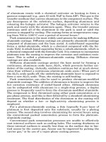
The following discussion illustrates the usage of anodic and cathodic
inhibitors for acid cleaning of industrial equipment. The combined
action of film growth and deposition from solution results in fouling
that has to be removed to restore the efficiency of heat exchangers,
boilers, and steam generators. E-pH diagrams indicate that the foul-
ing of iron-based boiler tubes, by Fe
3
O
4
and Fe
2
O
3
, can be dissolved in
Corrosion Inhibitors 841
0765162_Ch10_Roberge 9/1/99 6:15 Page 841
either the acidic or alkaline corrosion regions. In practice, inhibited
hydrochloric acid has been repeatedly proven to be the most efficient
method to remove fouling. Four equations are basically needed to
explain the chemistry involved in fouling removal. Three of those
equations represent cathodic processes [Eqs. (10.2) and (10.3); A, A′
and A" in Figs. 10.1 and 10.2; and Eq. (10.4); B in Figs. 10.1 and 10.2]
and one anodic process [i.e., the dissolution of tubular material [Eq.
(10.5); C in Figs. 10.1 and 10.2]:
3
Fe
2
O
3
ϩ 4 Cl
Ϫ
ϩ 6 H
ϩ
ϩ 2 e
Ϫ
→ 2 FeCl
2(aq)
ϩ 3 H
2
O (10.2)
Fe
3
O
4
ϩ 6 Cl
Ϫ
ϩ 8 H
ϩ
ϩ 2 e
Ϫ
→ 3 FeCl
2(aq)
ϩ 4 H
2
O (10.3)
2 H
ϩ
ϩ2 e
Ϫ
→ H
2
(10.4)
Fe ϩ 2 Cl
Ϫ
→ FeCl
2(aq)
ϩ 2 e
Ϫ
(10.5)
These equations indicate that the base iron functions as a reducer to
accelerate the dissolution of iron oxides. Because it is difficult to deter-
mine the endpoint for the dissolution of fouling oxides, an inhibitor is
generally added for safety purpose. Both anodic and cathodic inhibitors
could be added to retard the corrosion of the bare metal after dissolution
of the fouling oxides. Figures 10.1 and 10.2 illustrate the action that
could be played by either an anodic inhibitor (Fig. 10.1) or a cathodic
inhibitor (Fig. 10.2). It can be seen that although the anodic inhibitor
retards the anodic dissolution of iron at the endpoint, it concurrently
decreases the rate of oxide dissolution permitted by the chemical system.
On the other hand, the cathodic inhibitor retards both the reduction
of protons into hydrogen and the dissolution of the base, whereas the
reduction of the fouling oxides is left unaffected. The E-pH diagrams
also indicate that the dissolution of the fouling oxides is also possible in
alkaline solutions. But the kinetics of anodic and cathodic reactions
in high pH environments are much slower, and therefore these reac-
tions are less useful.
Electrochemical studies have shown that inhibitors in acid solutions
may affect the corrosion reactions of metals in the following main ways.
Formation of a diffusion barrier. The absorbed inhibitor may form a sur-
face film that acts as a physical barrier to restrict the diffusion of ions
or molecules to or from the metal surface and so retard the rate of cor-
rosion reactions. This effect occurs particularly when the inhibitor
species are large molecules (e.g., proteins, such as gelatin or agar agar,
polysaccharides, such as dextrin, or compounds containing long hydro-
carbon chains). Surface films of these types of inhibitors give rise to
resistance polarization and also concentration polarization affecting
both anodic and cathodic reactions.
842 Chapter Ten
0765162_Ch10_Roberge 9/1/99 6:15 Page 842
Blocking of reaction sites. The simple blocking decreases the number of
surface metal atoms at which corrosion reactions can occur. The mech-
anisms of the reactions are not affected, and the Tafel slopes of the
polarization curves remain unchanged. It should be noted that the
anodic and cathodic processes may be inhibited to different extents.
The anodic dissolution process of metal ions is considered to occur at
steps or emergent dislocations in the metal surface, where metal
atoms are less firmly held to their neighbors than in the plane surface.
These favored sites occupy a relatively small proportion of the metal
surface. The cathodic process of hydrogen evolution is thought to occur
on the plane crystal faces that form most of the metal surface area.
Adsorption of inhibitors at low surface coverage tends to occur prefer-
entially at anodic sites, causing retardation of the anodic reaction. At
higher surface coverage, adsorption occurs on both anodic and cathodic
sites, and both reactions are inhibited.
Participation in the electrode reactions. Corrosion reactions often
involve the formation of adsorbed intermediate species with surface
metal atoms [e.g., adsorbed hydrogen atoms in the hydrogen evolu-
tion reaction and adsorbed (FeOH) in the anodic dissolution of iron].
Corrosion Inhibitors 843
Log current
Potential
A'
without inhibitor
A (start point)
B
C
E
M
E
MO
E
2
with inhibitor
E
H
E
1
A''
(end point)
Figure 10.1 The effect of an anodic inhibitor on the dissolution rate of iron and iron oxide.
3
0765162_Ch10_Roberge 9/1/99 6:15 Page 843
The presence of adsorbed inhibitors will interfere with the formation
of these adsorbed intermediates, but the electrode processes may
then proceed by alternative paths through intermediates containing
the inhibitor. In these processes the inhibitor species act in a cat-
alytic manner and remain unchanged. Such participation by the
inhibitor is generally characterized by an increase in the Tafel slope
of the anodic dissolution of the metal.
Inhibitors may also retard the rate of hydrogen evolution on metals
by affecting the mechanism of the reaction, as indicated by increases in
the Tafel slopes of cathodic polarization curves. This effect has been
observed on iron in the presence of inhibitors such as phenyl-thiourea,
acetylenic hydrocarbons, aniline derivatives, benzaldehyde derivatives.
and pyrilium salts.
Alteration of the electrical double layer. The adsorption of ions or species
that can form ions on metal surfaces will change the electrical double
layer at the metal-solution interface, and this in turn will affect the
rates of the electrochemical reactions. The adsorption of cations, such as
quaternary ammonium ions and protonated amines, makes the poten-
tial more positive in the plane of the closest approach to the metal of
844 Chapter Ten
Log current
Potential
A'
without inhibitor
A (start point)
B
C
E
M
E
MO
E
H
A'' (end point)
E
2
E
1
with
inhibitor
Figure 10.2 The effect of a cathodic inhibitor on the dissolution rate of iron and iron oxide.
3
0765162_Ch10_Roberge 9/1/99 6:15 Page 844
846 Chapter Ten
-405
-800 -600 -400 -200 0 200 400
-400
-395
-390
-385
-380
-375
-370
-365
-360
-355
Current density (µA cm
-2
)
E (mV vs. SHE)
Figure 10.3 Corrosion of AISI 1018 carbon steel in 6 M HCl containing 250 ppm trans-cinnamaldehyde.
-410
-150 -100 -50 0 50 100 150
-405
-400
-395
-390
-385
-380
-375
-370
-365
-360
Current density (µA cm
-2
)
E (mV vs. SHE)
Figure 10.4 Corrosion of AISI 1018 carbon steel in 6 M HCl containing 500 ppm trans-cinnamaldehyde.
0765162_Ch10_Roberge 9/1/99 6:15 Page 846
cathodic reaction in neutral solutions is the reduction of dissolved oxy-
gen, whereas in acid solution it is hydrogen evolution. Corroding metal
surfaces in acid solution are oxide-free, whereas in neutral solutions
metal surfaces are covered with films of oxides, hydroxides, or salts,
owing to the reduced solubility of these species. Because of these differ-
ences, substances that inhibit corrosion in acid solution by adsorption on
oxide-free surfaces do not generally inhibit corrosion in neutral solution.
Typical inhibitors for near-neutral solutions are the anions of weak
acids, some of the most important in practice being chromate, nitrite,
benzoate, silicate, phosphate, and borate. Passivating oxide films on
metals offer high resistance to the diffusion of metal ions, and the
anodic reaction of metal dissolution is inhibited. These inhibitive
anions are often referred to as anodic inhibitors, and they are more
Corrosion Inhibitors 847
-415
-100 -80 -60 -40 -20 0 20 40 60 80 100 120
-410
-405
-400
-395
-390
-385
-380
-375
-370
-365
Current density (µA cm
-2
)
E (mV vs. SHE)
Figure 10.5 Corrosion of AISI 1018 carbon steel in 6 M HCl containing 1000 ppm trans-cinnamaldehyde.
TABLE 10.2 Inhibitor Efficiency of Trans-Cinnamaldehyde (TCA) to the
Corrosion of Carbon Steel Exposed to a 6 M HCl Solution
Corrosion current, Corrosion rate,
TCA, ppm R
p
, ⍀иcm
2
mAиcm
Ϫ2
mmиy
Ϫ1
Efficiency, %
0 14 1.55 18.0 0
250 35 0.62 7.2 60
1000 143 0.152 1.76 90
5000 223 0.097 1.13 94
0765162_Ch10_Roberge 9/1/99 6:15 Page 847
generally used than cathodic inhibitors to inhibit the corrosion of iron,
zinc, aluminum, copper, and their alloys in near-neutral solutions. The
action of inhibitive anions on the corrosion of metals in near-neutral
solution involves the following important functions:
1. Reduction of the dissolution rate of the passivating oxide film
2. Repair of the oxide film by promotion of the reformation of oxide
3. Repair of the oxide film by plugging pores with insoluble com-
pounds
4. Prevention of the adsorption of aggressive anions
Of these functions, the most important appears to be the stabilization
of the passivating oxide film by decreasing its dissolution rate (func-
tion 1). Inhibitive anions probably form a surface complex with the
metal ion of the oxide (i.e., Fe
3ϩ
, Zn
2ϩ
, Al
3ϩ
), such that the stability of
this complex is higher than that of the analogous complexes with
water, hydroxyl ions, or aggressive anions.
Stabilization of the oxide films by repassivation is also important
(function 2). The plugging of pores by formation of insoluble com-
pounds (function 3) does not appear to be an essential function but is
valuable in extending the range of conditions under which inhibition
can be achieved. The suppression of the adsorption of aggressive
anions (function 4) by participation in a dynamic reversible competi-
tive adsorption equilibrium at the metal surface appears to be related
to the general adsorption behavior of anions rather than to a specific
property of inhibitive anions.
Inhibition in neutral solutions can also be due to the precipitation of
compounds, on a metallic surface, that can form or stabilize protective
films. The inhibitor may form a surface film of an insoluble salt by pre-
cipitation or reaction. Inhibitors forming films of this type include
■
Salts of metals such as zinc, magnesium, manganese, and nickel, which
form insoluble hydroxides, especially at cathodic areas, which are more
alkaline due to the hydroxyl ions produced by reduction of oxygen
■
Soluble calcium salts, which can precipitate as calcium carbonate in
waters containing carbon dioxide, again at cathodic areas where the
high pH permits a sufficiently high concentration of carbonate ions
■
Polyphosphates in the presence of zinc or calcium, which produce a
thin amorphous salt film
These salt films, which are often quite thick and may even be visible,
restrict diffusion, particularly of dissolved oxygen to the metal surface.
They are poor electronic conductors, and so oxygen reduction does not
848 Chapter Ten
0765162_Ch10_Roberge 9/1/99 6:15 Page 848
occur on the film surface. These inhibitors are referred to as cathodic
inhibitors.
The following sections discuss the mechanism of action of inhibitive
anions on iron, zinc, aluminum, and copper.
Iron. Corrosion of iron (or steel) can be inhibited by the anions of most
weak acids under suitable conditions. However, other anions, particu-
larly those of strong acids, tend to prevent the action of inhibitive
anions and stimulate breakdown of the protective oxide film. Examples
of such aggressive anions include the halides, sulfate, and nitrate. The
balance between the inhibitive and aggressive properties of a specific
anion depends on the following main factors (which are themselves
interdependent):
■
Concentration. Inhibition of iron corrosion in distilled water occurs
only when the anion concentration exceeds a critical value. At con-
centrations below the critical value, inhibitive anions may act
aggressively and stimulate breakdown of the oxide films. Effective
inhibitive anions have low critical concentrations for inhibition. A
number of anions have been classified in order of their inhibitive
power toward steel, judged from their critical inhibitive concentra-
tions. The order of decreasing inhibitive efficiency is azide, ferri-
cyanide, nitrite, chromate, benzoate, ferrocyanide, phosphate,
tellurate, hydroxide, carbonate, chlorate, o-chlorbenzoate, bicarbon-
ates fluoride, nitrate, and formate.
■
pH. Inhibitive anions are effective in preventing iron corrosion
only at pH values more alkaline than a critical value. This critical
pH depends on the anion.
■
Dissolved oxygen concentration and supply. Inhibition of the corro-
sion of iron by anions requires a critical minimum degree of oxidiz-
ing power in the solution. This is normally supplied by the dissolved
oxygen present in air-saturated solutions.
■
Aggressive anion concentration. When aggressive anions are pre-
sent in the solution, the critical concentrations of inhibitive anions
required for protection of iron are increased. It has been shown that
the relationship between the maximum concentration of aggressive
anion C
agg
permitting full protection by a given concentration of
inhibitive anion C
inh
is of the form
log C
inh
ϭ n log C
agg
ϩ K
where K is a constant dependent on the nature of the inhibitive and
aggressive anions, and n is an exponent that is approximately the
Corrosion Inhibitors 849
0765162_Ch10_Roberge 9/1/99 6:15 Page 849
ratio of the valency of the inhibitive anion to the valency of the
aggressive anion
■
Nature of the metal surface. The critical concentration of an anion
required to inhibit the corrosion of iron may increase with increas-
ing surface roughness.
■
Temperature. In general, the critical concentrations of anions (e.g.,
benzoate, chromate, and nitrite) required for the protection of steel
increase as the temperature increases.
Zinc. The effects of inhibitive and aggressive anions on the corrosion
of zinc are broadly similar to the effects observed with iron. Thus with
increasing concentration, anions tend to promote corrosion but may
give inhibition above a critical concentration. Inhibition of zinc corro-
sion is somewhat more difficult than that of iron (e.g., nitrite and ben-
zoate are not efficient inhibitors for zinc). However, inhibition of zinc
corrosion is observed in the presence of anions such as chromates,
borate, and nitrocinnamate, which are also good inhibitors for the cor-
rosion of iron. Anions such as sulfate, chloride, and nitrate are aggres-
sive toward zinc and prevent protection by inhibitive anions. The
presence of dissolved oxygen in the solution is essential for protection
by inhibitive anions. As in the case of iron, pressures of oxygen greater
than atmospheric or an increase in oxygen supply by rapid stirring can
lead to the protection of zinc in distilled water. Inhibition of zinc cor-
rosion occurs most readily in the pH range of 9 to 12, which corre-
sponds approximately to the region of minimum solubility of zinc
hydroxide.
The ways in which inhibitive anions affect the corrosion of zinc are
mainly similar to those described above for iron. In inhibition by chro-
mate, localized uptake of chromium has been shown to occur at low
chromate concentrations and in the presence of chloride ions.
Inhibitive anions also promote the passivation of zinc (e.g., passivation
is much easier in solutions of the inhibitive anion, borate, than in solu-
tions of the noninhibitive anions, carbonate and bicarbonate). A criti-
cal inhibition potential, analogous to that on iron, has been observed
for zinc in borate solutions. Thus inhibitive anions promote repair of
the oxide film on zinc by repassivation with zinc oxide.
Aluminum. When aluminum is immersed in water, the air-formed
oxide film of amorphous ␥-alumina initially thickens (at a faster rate
than in air) and then an outer layer of crystalline hydrated alumina
forms, which eventually tends to stifle the reaction. In near-neutral air-
saturated solutions, the corrosion of aluminum is generally inhibited
by anions that are inhibitive for iron (e.g., chromate, benzoate, phos-
850 Chapter Ten
0765162_Ch10_Roberge 9/1/99 6:15 Page 850
50 ppm, based on total liquid production. A much wider variety of
inhibitor chemistry is available today for combating oil-field corrosion
than existed only a decade ago. In recent years, organic molecules con-
taining sulfur, phosphorus, and nitrogen in various combinations have
been developed. These inhibitor types have extended the performance
of oil-field inhibitors, particularly in the directions of being tolerant of
oxygen contamination and of controlling corrosion associated with
high CO
2
, low H
2
S conditions.
7
Most of the inhibitors currently used in producing wells are organic
nitrogenous compounds. The basic types have long-chain hydrocar-
bons (usually C
18
) as a part of the structure. Most inhibitors in suc-
cessful use today are either based on the long-chain aliphatic diamine,
or on long carbon chain imidazolines. Various modifications of these
structures have been made to change the physical properties of the
material (e.g., ethylene oxide is commonly reacted with these com-
pounds in various molecular percentages to give polyoxy-ethylene
derivatives that have varying degrees of brine dispersibility). Many
carboxylic acids are used to make salts of these amines or imidazo-
lines. Inhibitors in general petroleum production can be classified as
follows:
8
■
Amides/imidazolines
■
Salts of nitrogenous molecules with carboxylic acids
■
Nitrogen quaternaries
■
Polyoxyalkylated amines, amides, and imidazolines
■
Nitrogen heterocyclics and compounds containing P, S, O
There are several hypotheses and theories concerning the inhibitive
action of the long-chain nitrogenous compounds. One of the classical
concepts is the so-called sandwich theory in which the bottom part of
the sandwich is the bond between the polar end of the molecule and
the metal surface. The strength of the protective action depends on
this bond. The center portion of the sandwich is the nonpolar end of
the molecule and its contribution toward protection is the degree to
which this portion of the molecule can cover or wet the surface. The top
portion of the protective sandwich is the hydrophobic layer of oil
attached to the long carbon tail of the inhibitor. This oil layer serves as
the external protective film, covering the inhibitor film and creating a
barrier to both outward diffusion of ferrous ion and inward diffusion of
corrosive species.
Water or water solutions of salts alone will not cause damaging cor-
rosion unless they contain specific corrodents, such as CO
2
, H
2
S, and
their products of dissolution. Oil and gas wells are either sweet or sour.
852 Chapter Ten
0765162_Ch10_Roberge 9/1/99 6:15 Page 852
Sweet wells do not contain hydrogen sulfide, whereas sour wells do.
The source of CO
2
can be mineral dissolution or a by-product of the
petroleum-forming process. The source of H
2
S can be dissolution of
mineral deposits in the rocks, a by-product of the petroleum-forming
process, or bacterial action at any time in the history of the petroleum
deposit. Oxygen always originates from air and can only come in con-
tact with petroleum fluids after the recovery process begins. It does
not exist in the undisturbed hydrocarbon deposit.
The dissolution products of H
2
S in oil-field waters will be dissolved
hydrogen sulfide molecules (H
2
S) and bisulfide ions (HS
Ϫ
), and the dis-
solution products of CO
2
will be dissolved CO
2
molecules (some
hydrate to form H
2
CO
3
) and bicarbonate (HCO
3
Ϫ
) ions. The pH of these
waters is not basic enough to produce appreciable amounts of sulfide
or carbonate ions. However, damaging corrosion in the oil field nearly
always takes localized forms, often pitting. Corrosion pits in oil-field
steels typically penetrate at 10 to 100 times the rate of uniform corro-
sion. Pit growth in steels exposed to brine, an active corrosion system,
occurs because of a galvanic couple between filmed metal and rela-
tively bare metal.
Sweet corrosion. Corrosion in CO
2
gas wells can be divided into three
temperature regimes. Below 60°C, the corrosion product is nonprotec-
tive and high corrosion rates will occur. Above approximately 150°C,
magnetite is formed, and the wells are not corrosive except in the pres-
ence of high brine levels. In the middle temperature regime, in which
most gas well conditions lie, the iron carbonate corrosion product layer
is protective but is affected adversely by chlorides and fluid velocity.
7
One of the important physical properties of oil-field inhibitors is
their volubility or dispersibility characteristic in the oil and the brine
being produced. An inhibitor, properly chosen on the basis of the cor-
rosion mechanism, will not be effective if it does not have access to the
corroding metal. When it comes to treating oil and gas wells, there are
also some important differences. The distinction between an oil well
and a gas well is not clear cut. Often the distinction is made on the
basis of economics or workload balance within a producing company.
The facts that many oil wells produce a considerable volume of gas and
many gas wells produce a considerable volume of liquid, plus the fact
that wells often experience a shift in production during their lifetime,
make a technical distinction difficult. However, there are more impor-
tant differences. Typical gas wells are much hotter than oil wells, and
the hydrocarbon liquids are much lighter. Gas wells are normally
much deeper and usually produce lower total dissolved solids (TDS)
brines. Oxygen is not a factor to consider in gas well corrosion but can
cause major problems in artificial lift oil wells.
Corrosion Inhibitors 853
0765162_Ch10_Roberge 9/1/99 6:15 Page 853
Due to the large temperature gradient in many gas wells, corrosion
mechanisms can change, resulting in different types of corrosion in the
same well, whereas oil wells do not exhibit this behavior. Normally, oil
wells produce more liquid than gas wells, resulting in a shorter treat-
ment life when batch treated. Because corrosion in oil wells is electro-
chemical in nature, an electrolyte must be present for corrosion to
occur. In oil wells, the source of the water is nearly always the pro-
ducing formation, and the water will contain dissolved salts in con-
centrations ranging from traces to saturation. Water associated with
corrosion may be in a thin layer, in droplets, or even the major phase.
Results of the study of corrosion control by inhibitors in producing oil
wells in carbon dioxide flooded fields
8
showed imidazolines are success-
ful in protection in CO
2
brines. The inhibitor was found to be incorpo-
rated in the carbonate corrosion product layer but was still more
effective if the surface film contained sulfide. Also, better results were
obtained with inhibitors, such as nitrogen-phosphorus compounds or
compounds with sulfur in the organic molecules.
Sour corrosion. In sour wells, hydrogen sulfide is the primary corro-
sive agent, and frequently carbon dioxide is present as well. The pres-
ence of various iron sulfides in the corrosion products at different
concentrations of hydrogen sulfide has been identified. Based on this
evidence the net corrosion reaction due to hydrogen sulfide can be
written as follows:
Fe ϩ H
2
S → FeS ϩ 2 H
ϩ
ϩ 2 e
Ϫ
(10.6)
The most probable mechanism to explain the accelerating effect of
hydrogen sulfide involves the formation of a molecular surface com-
plex that can yield hydrogen atoms according to Eqs. (10.7) to (10.9).
Some of the hydrogen produced in the process [Eq. (10.9)] may recom-
bine to form molecular gaseous hydrogen, whereas some can diffuse in
the metal and eventually cause blistering or hydrogen induced crack-
ing.
9
Fe ϩ HS
Ϫ
→ Fe (HS
Ϫ
)
ads
(10.7)
Fe (HS
Ϫ
)
ads
ϩ H
ϩ
→ Fe (H-S-H)
ads
(10.8)
Fe (H-S-H)
ads
ϩ e
Ϫ
→ Fe (HS
Ϫ
)
ads
ϩ H
ads
(10.9)
Corrosion inhibitors used in the past to combat corrosion in sour
wells include aldehydes, cyanamide thiourea, and urea derivatives.
The most widely used inhibitors are organic amines. Although organic
amines are known to be less effective inhibitors in acid solution, inhi-
bition by amines in the presence of hydrogen sulfide is greatly
854 Chapter Ten
0765162_Ch10_Roberge 9/1/99 6:15 Page 854
enhanced.
9
Oil-field inhibitors function by incorporating into a thin
layer of corrosion product on the metal surface. This surface film may
be a sulfide or a carbonate and may be anaerobic or partially oxidized.
Some types of inhibitor molecules incorporate better in one type of film
than others. For example, amine inhibitors are not effective when oxy-
gen is present. Inhibitor molecules containing nitrogen (e.g., imidazo-
lines) will incorporate into either sulfide or carbonate films but are
more effective when the film contains some sulfide.
Acidizing. An important procedure for stimulation of oil and gas well
production is acidizing. Because of the very low permeability of certain
formations containing hydrocarbons, these are not able to flow readily
into the well. Formations composed of limestone or dolomite may be
treated with HCl or, if the rock is sandstone, a mixture containing HF.
In the acidizing treatment, the acid (e.g., HCl, at a concentration of 7
to 28%) is pumped down the tubing into the well where it enters the
perforations and contacts the formation; the acid etches channels that
provide a way for oil and gas to enter the well.
8
Many inhibitors are
used for well acidizing operations, mainly high molecular weight
nitrogenous compounds such as those used in primary production or
the reaction products of these compounds with unsaturated alcohols.
Many of those commercial inhibitors contain alkyl or alkylaryl nitro-
gen compounds and acetylenic alcohols, such as 1-octyn-3-ol. These
products present serious handling problems because they are very tox-
ic; this can determine which product is actually used by an operator.
Furthermore, their effectiveness is limited both in efficiency and time.
Acid soaks normally last between 12 and 24 h, after which time
inhibitor efficiency can start to fall off alarmingly.
Oxygen-containing inhibitors that are successful in concentrated
HCl include cinnamaldehyde and the alkynols containing unsaturated
groups conjugated with the oxygen function described as alpha-
alkenylphenones.
8
They provide, especially when mixed with small
amounts of surfactants, protection similar to that obtained with
acetylenic alcohols.
Oxygen-influenced corrosion. Oil-producing formations originally con-
tain no oxygen. During the process of bringing oil to the surface, oxy-
gen from air contamination may dissolve into produced fluids. This
oxygen has three consequences:
1. Oxygen can readily accept electrons, so it increases the rate of
corrosion.
2. The nature of the surface corrosion product changes, so the chemi-
cal properties required for effective inhibitor incorporation change.
Corrosion Inhibitors 855
0765162_Ch10_Roberge 9/1/99 6:15 Page 855
3. Oxidation of certain ions in solution leads to increased precipitation
of solid phases.
Air may be pulled into the annuli of wells having little gas pressure
as a consequence of the artificial lift process or of negative-pressure gas
gathering systems. In some cases, in situ combustion stimulation can
introduce oxygen into the formation itself. On the surface, small
amounts of oxygen can be introduced into production liquids by leaking
pump packing or direct contact during storage.
10
In water flooding, the same types of inhibitors as described for pri-
mary production are currently used. The most effective and most fre-
quently used are the quaternary ions of the fatty or the imidazoline
types. They are also good bactericides and dispersive agents.
Combination of amino-methylene phosphonate and zinc salts have been
used successfully in circulating water systems and have provided more
effective protection than the inorganic phosphate-zinc salts. Organic
sulfonates have recently been introduced into practice.
Oxygen is practically always present in drilling muds. The most
effective control of oxygen corrosion would be to keep it out of the sys-
tem, but this is difficult because the drilling fluid is exposed to the
atmosphere as it circulates through the pit. The attack is almost
always in the form of pitting, which in a short time can produce irre-
versible damage to drilling equipment. Oxygen activity in drilling
muds is determined by the interplay of a number of factors. For exam-
ple, phosphorus compounds such as sodium hexametaphosphate,
phosphate esters of organic alcohol, and organic phosphonates may act
as anodic inhibitors, but a precaution is required in their use because
they have a strong tendency to thin nondispersed muds. Tannins and
lignins are thinners for high-solid muds, and they also have a certain
inhibitive influence.
Application methods. The selection of an inhibitor is of prime impor-
tance, but the proper application of an inhibitor is even more
important. If an inhibitor does not reach the corrosive areas, it cannot
be effective. Maximum corrosion protection can be achieved by con-
tinuous injection of inhibitor through a dual tubing string (kill
string), a capillary tubing, a side mandrel valve, or even perforated
tubing. Any of these methods will supply a continuous residual of
inhibitor to maintain corrosion protection. Treating rates or inhibitor
concentrations are best based on the volume of fluid produced and can
range from near 50 ppm to over 1000 ppm, depending on the severity
of the conditions.
7
Many gas wells are not equipped with facilities for continuous treat-
ment and must be treated by some type of batch or slug treatment. The
856 Chapter Ten
0765162_Ch10_Roberge 9/1/99 6:15 Page 856
inhibitors by electrochemically changing the kinetics of electrode reac-
tions should be classified as VCIs. Neutralizing amines have an appre-
ciable vapor pressure and are effective inhibitors for ferrous metals,
but their mechanism is based on adjusting the pH value of the elec-
trolyte, thus creating conditions that are inhospitable for rust forma-
tion. Hence, they should not necessarily be classified as volatile
corrosion inhibitors .
Volatile compounds reach the protective vapor concentration rapidly,
but in the case of enclosures that are not airtight, the consumption of
inhibitor is excessive and the effective protective period is short. Low
vapor pressure inhibitors are not rapidly exhausted and can ensure
more durable protection. However, more time is required to achieve a
protective vapor concentration. Furthermore, there is a possibility of
corrosion occurring during the initial period of saturation, and if the
space is not hermetically sealed, an effective inhibitor concentration
may never be obtained. Therefore, the chemical compound used as a
volatile inhibitor must not have too high or too low a vapor pressure,
but some optimum vapor pressure.
12
The comparison between the vapor pressure of a compound and its
molecular heat of sublimation shows a marked decrease in vapor pres-
sure values with an increase in heat of sublimation. A plausible expla-
nation is that a decrease in vapor pressure is caused by steric
intermolecular actions between functional groups and by an increase
in molecular weight of the compound (Table 10.3).
12
It is significant that the most effective volatile corrosion inhibitors
are the products of the reaction of a weak volatile base with a weak
volatile acid. Such substances, although ionized in aqueous solutions,
undergo substantial hydrolysis, the extent of which is almost indepen-
858 Chapter Ten
TABLE 10.3 Saturated Vapor Pressures of Common VCIs
Temperature, Vapor pressure, Melting
Substance °C mmиHg point, °C
Morpholine 20 8.0
Benzylamine 29 1.0
Cyclohexylamine carbonate 25.3 0.397
Diisopropylamine nitrite 21 4.84 ϫ 10
Ϫ3
139
Morpholine nitrite 21 3 ϫ 10
Ϫ3
Dicyclohexylamine nitrite 21 1.3 ϫ 10
Ϫ4
179
Cyclohexylamine benzoate 21 8 ϫ 10
Ϫ5
Dicyclohexylamine caprylate 21 5.5 ϫ 10
Ϫ4
Guanadine chromate 21 1 ϫ 10
Ϫ5
Hexamethyleneimine benzoate 41 8 ϫ 10
Ϫ4
64
Hexamethyleneamine nitrobenzoate 41 1 ϫ 10
Ϫ6
136
Dicyclohexylamine benzoate 41 1.2 ϫ 10
Ϫ6
210
0765162_Ch10_Roberge 9/1/99 6:15 Page 858
dent of concentration. In the case of the amine nitrites and amine car-
boxylates, the net result of those reactions may be expressed as
H
2
O ϩ R
2
NH
2
NO
2
→ (R
2
NH
2
)
ϩ
:OH
Ϫ
ϩ H
ϩ
:(NO
2
Ϫ
) (10.10)
The nature of the adsorbed film formed at the steel-water interface
is an important factor controlling the efficiency of VCIs. Metal sur-
faces exposed to vapors from VCIs in closed containers give evidence
of having been covered by a hydrophobic-adsorbed layer. The contact
angle of distilled water on such surfaces increases with time of expo-
sure. Experimental studies on the adsorption of volatile inhibitors
from the gas phase confirm the assumption that the VCIs react with
the metal surface, thus providing corrosion protection. When a steel
electrode is exposed to vapors of a VCI, the steady-state electrode
potential shifts considerably into the region of positive values. The
higher the vapor pressure, the stronger the shift of the electrode
potential in the positive direction. Inhibitor adsorption is not a
momentary process and requires much time for completion. This indi-
cates that the adsorption is chemical and not physical in nature,
resulting in a chemisorbed layer on the metal surface. In proper con-
ditions, the inhibitor molecule will become dissociated or undissociated
from the vapor phase and will dissolve into the water layer, with sev-
eral possible effects (i.e., on the pH, surface wetting, and electro-
chemical processes at the metal/aqueous film interface).
It is well known, and shown in potential-pH diagrams, that an alka-
lization of the corrosive medium has a beneficial effect on the corrosion
resistance of some metals, notably ferrous metals. Cyclohexylamine
and dicyclohexylamine are moderately strong bases (pK
a
ϭ 10.66 and
11.25, respectively). The pH of the solutions of their salts with weak
acids will depend on the pK
a
of the acid. For example, cyclohexylamine
carbonate will have a rather alkaline pH (pK
a
for carbonic acid: 6.37),
whereas dicyclohexyl ammonium nitrite will have a neutral pH (pK
a
ϭ
3.37 for nitrous acid). Guanidine is a strong base (pK
a
ϭ 13.54) and is
mainly used as an additive in VCI formulations to adjust the alkalin-
ity. Buffers (sodium tetraborate, etc.) may have to be used to maintain
the pH of a VCI formulation at a convenient level.
The effect of a volatile inhibitor on the electrochemical processes at
the metal surface is first evidenced by the shift in the steady-state elec-
trode potential when an electrode is exposed to vapors of the volatile
inhibitor.
11
The positive shift generally observed with most of the VCIs
on ferrous metals is indicative of a preferentially anodic effect of the
inhibitors. This anodic effect may be related either to a simple blocking
effect of the anodic sites by the amine part of the inhibitors or to the
contribution of the anionic component (i.e., the weak acid component).
Corrosion Inhibitors 859
0765162_Ch10_Roberge 9/1/99 6:15 Page 859
7. French, E. C., Martin, R. L., and Dougherty, J. A., Corrosion and Its Inhibition in Oil
and Gas Wells, in Raman, A., and Labine, P. (eds.), Reviews on Corrosion Inhibitor
Science and Technology, Houston, Tex., NACE International, 1993, pp. II-1-1–II-1-25.
8. Lahodny-Sarc, O., Corrosion Inhibition in Oil and Gas Drilling and Production
Operations, in A Working Party Report on Corrosion Inhibitors, London, U.K., The
Institute of Materials, 1994, pp. 104–120.
9. Sastri, V. S., Roberge, P. R., and Perumareddi, J. R., Selection of Inhibitors Based on
Theoretical Considerations, in Roberge, P. R., Szklarz, K., and Sastri, S. (eds.),
Material Performance: Sulphur and Energy, Montreal, Canada, Canadian Institute
of Mining, Metallurgy and Petroleum, 1992, pp. 45–54.
10. Thomas, J. G. N., The Mechanism of Corrosion, in Shreir, L. L., Jarman, R. A., and
Burstein, G. T. (eds.), Corrosion Control, Oxford, UK, Butterworths Heinemann,
1994, pp. 17:40–17:65.
11. Fiaud, C., Theory and Practice of Vapour Phase Inhibitors, in A Working Party
Report on Corrosion Inhibitors, London, U.K., The Institute of Materials, 1994, pp.
1–11.
12. Miksic, B. A., Use of Vapor Phase Inhibitors for Corrosion Protection of Metal
Products, in Raman, A., and Labine, P. (eds.), Reviews on Corrosion Inhibitor Science
and Technology, Houston, Tex., NACE International, 1993, pp. II-16-1–II-16-13.
13. Mercer, A. D., Corrosion Inhibition: Principles and Practice, in Shreir, L. L., Jarman,
R. A., and Burstein, G.T. (eds.), Corrosion Control, Oxford, UK, Butterworths
Heinemann, 1994, pp. 17:11–17:39.
862 Chapter Ten
0765162_Ch10_Roberge 9/1/99 6:15 Page 862
Cathodic Protection
11.1 Introduction 863
11.1.1 Theoretical basis 864
11.1.2 Protection criteria 866
11.1.3 Measuring potentials for protection criteria 867
11.2 Sacrificial Anode CP Systems 871
11.2.1 Anode requirements 872
11.2.2 Anode materials and performance characteristics 873
11.2.3 System design and installation 874
11.3 Impressed Current Systems 878
11.3.1 Impressed current anodes 880
11.3.2 Impressed current anodes for buried applications 881
11.3.3 Ground beds for buried structures 884
11.3.4 System design 885
11.4 Current Distribution and Interference Issues 886
11.4.1 Corrosion damage under disbonded coatings 886
11.4.2 General current distribution and attenuation 888
11.4.3 Stray currents 892
11.5 Monitoring the Performance of CP Systems for
Buried Pipelines 904
11.5.1 CP system hardware performance monitoring 904
11.5.2 Structure condition monitoring 905
References 919
11.1 Introduction
The basic principle of cathodic protection (CP) is a simple one.
Through the application of a cathodic current onto a protected struc-
ture, anodic dissolution is minimized. Cathodic protection is often
applied to coated structures, with the coating providing the primary
form of corrosion protection. The CP current requirements tend to be
excessive for uncoated systems. The first application of CP dates back
Chapter
11
863
0765162_Ch11_Roberge 9/1/99 6:37 Page 863
An Evans diagram can provide the theoretical basis of CP. Such a
diagram is shown schematically in Fig. 11.2, with the anodic metal
dissolution reaction under activation control and the cathodic reac-
tion diffusion limited at higher density. As the applied cathodic cur-
rent density is stepped up, the potential of the metal decreases, and
the anodic dissolution rate is reduced accordingly. Considering the
logarithmic current scale, for each increment that the potential of
the metal is reduced, the current requirements tend to increase
exponentially.
In anaerobic, acidic environments the hydrogen evolution reaction
tends to occur at the cathodically protected structure, whereas oxy-
gen reduction is a likely cathodic reaction in aerated, near-neutral
environments:
2H
ϩ
ϩ 2e
Ϫ
→ H
2
(anaerobic, acidic environments)
O
2
ϩ 2H
2
O ϩ 4e
Ϫ
→ 4OH
Ϫ
(near-neutral environments)
Cathodic Protection 865
Potential
Log Current
Density
Potential of
structure
without CP
Potential of
structure
with CP
Corrosion current
density with CP
Corrosion current
density without CP
Increasing CP current
requirements as
potential of
structure is
lowered
Anodic reaction
under activation control
Cathodic reaction
under diffusion control
Current density required
in application of CP
Figure 11.2 Evans diagram illustrating the increasing CP current requirements as the
potential of the structure is lowered to reduce the anodic dissolution rate.
0765162_Ch11_Roberge 9/1/99 6:37 Page 865
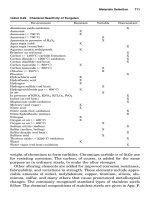
TABLE 11.2 Selected Cathodic Protection Criteria for Different Materials
Material CP criteria Standard/reference
Buried steel and cast iron Ϫ850 mV vs. Cu/CuSO
4
NACE Standard RP0169-83
(not applicable to
applications in concrete)
Minimum negative 300-mV shift under application of CP NACE Standard RP0169-83
Minimum positive 100-mV shift when depolarizing (after CP current
switched off) NACE Standard RP0169-83
Ϫ850 mV vs. Cu/CuSO
4
in aerobic environment British Standard CP 1021:1973
Ϫ950 mV vs. Cu/CuSO
4
in anaerobic environment British Standard CP 1021:1973
Steel (offshore pipelines) Ϫ850 mV vs. Cu/CuSO
4
NACE Standard RP0675-75
Minimum negative 300-mV shift under application of CP NACE Standard RP0675-75
Minimum positive 100-mV shift when depolarizing (after CP current
switched off) NACE Standard RP0675-75
Aluminum Minimum negative potential shift of 150 mV under application of CP NACE Standard RP0169-83
Positive 100-mV shift when depolarizing (after CP current switched off) NACE Standard RP0169-83
Positive limit of Ϫ950 mV vs. Cu/CuSO
4
British Standard CP 1021:1973
Negative limit of Ϫ1200 mV vs. Cu/CuSO
4
Negative limit of Ϫ1200 mV vs. Cu/CuSO
4
NACE Standard RP0169-83
Copper Positive 100-mV shift when depolarizing (after CP current switched off) NACE Standard RP0169-83
Lead Ϫ650 mV vs. Cu/CuSO
4
British Standard CP 1021:1973
Dissimilar metals Protection potential of most reactive (anodic) material should be reached NACE Standard RP0169-83
868
0765162_Ch11_Roberge 9/1/99 6:37 Page 868
Cathodic Protection 869
Reference Electrode
at Surface
Voltmeter
E
measured
=E
I
+ E
IR
Buried Pipeline Wall
Soil
E
IR
E
I
Pipe-Soil
Interface
Figure 11.3 Schematic illustration of the IR drop error introduced during pipeline potential
measurements at ground level. (E
IR
ϭ IR drop potential and E
I
ϭ pipe-to-soil potential.)
0765162_Ch11_Roberge 9/1/99 6:37 Page 869
current is flowing through the soil and that the soil between the
pipeline and the reference electrode has a certain electrical resistance.
Unfortunately, when a surface potential reading is made, the IR drop
error will tend to give a false sense of security. In the presence of the IR
drop, the pipeline potential will actually appear to be more negative
than the true pipe-to-soil potential. It is thus hardly surprising that
regulatory authorities are increasingly demanding that corrections for
the IR drop error be made in assessments of buried structures.
To minimize this fundamental error, it has become customary to con-
duct so-called instant OFF potential readings, mainly in the case of
impressed current cathodic protection systems. On the practical level, in
systems involving numerous buried sacrificial anodes such readings are
usually not possible. In this approach, the impressed CP current is
interrupted briefly to theoretically provide a “true” pipe-to-soil potential
reading. This momentary interruption of current theoretically produces
a reading free from undesirable IR drop effects. The theoretical basis for
this methodology is illustrated in Fig. 11.4. In practice, a so-called wave-
form analysis has to be performed to establish a suitable time interval
following the current interruption for defining the OFF potential. As
shown in Fig. 11.4, transient potential spikes tend to occur in the tran-
sition from the ON to the OFF potential, which should be avoided in estab-
lishing the OFF potential. There is thus no incentive to determine the OFF
potential as soon as possible after interrupting the current; rather time
870 Chapter Eleven
Potential
Time
More negative values
“On” value
Switch rectifier off
“Off” value
Anodic spike(s)
from switching
Figure 11.4 Measurement of instant-OFF potentials, by interrupting the CP current sup-
ply (schematic).
0765162_Ch11_Roberge 9/1/99 6:37 Page 870