Hệ thống nhúng - Chương 2 ppt
Bạn đang xem bản rút gọn của tài liệu. Xem và tải ngay bản đầy đủ của tài liệu tại đây (350.88 KB, 22 trang )
1
Hệ thống nhúng
Thạc sĩ Lê Mạnh Hải
Embedded Systems
2
Lesson 2 : A loop in the pattern
Flight plan:
•
Embedded-control programs need a
framework, similar to the pilots’
pattern, so that the flow of code can be
managed.
•
Loops syntax in C
•
The 16-bit Timer1.
•
Two new MPLAB® SIM
–
“Animate”
–
“Logic Analyzer.”
3
Preflight checklist
•
MPLAB IDE, Integrated Development
Environment
•
MPLAB SIM, software simulator
•
MPLAB C30 compiler (Student Version)
4
The flight
1. Select “Project→Project Wizard”, to start creating a new project.
2. Select the PIC24FJ128GA010 device, and click Next.
3. Select the MPLAB C30 compiler suite and click Next.
4. Create a new folder and name it “Loop.” name the project “A Loop in the
Pattern,” and clickNext.
5. There is no need to copy any source fi les from the previous lessons; click
Next once more.
6. Click Finish to complete the Wizard set-up.
7. Open a new editor window.
Type the main program header:
//
// A loop in the pattern
//
1. Select “Project→AddNewFiletoProject”, to save the fi le as: “loop.c” and
have it automatically
2. added to the project source fi les list.
3. Save the project.
5
The flight
“What happens when all the code in the main() function has
been executed?”
The device will reset, and the entire program will execute
again…and again.
In fact, the compiler puts a special software reset instruction
right after the end of the main() function code
How to keep the system alive?
While loops
In C there are at least three ways to code a loop; here is the fi
rst—the while loop:
while ( x)
{
// your code here
}
6
Operators
( a || b) is true,
( a && b) is true
( !a) is false
There are, then, a number of operators that compare numbers
(integers of any kind and fl oating-point values, too) and
return logic values.
== the “equal-to” operator; notice it is composed of two equal
signs to distinguish it from the “assignment” operator we
used in the previous lesson,
!= the “NOT-equal to” operator,
> the “greater-than” operator,
>= the “greater-or-equal to” operator,
< the “less-than” operator,
<= the “less-than-or-equal to” operator.
7
While pattern
1. while ( 1)
2. {
3. // your code here
4. }
8
Real program
1. #include <p24fj128ga010.h>
2. main()
3. {
4. // init the control registers
5. TRISA = 0xff00; // PORTA pin 0 7 as output
6. // application main loop
7. while( 1)
8. {
9. PORTA = 0xff; // turn pin 0-7 on
10.PORTA = 0; // turn all pin off
11.}
12.}
Please guess how can we know the system is working or
not?
9
An animated simulation
•
To test the code in this example with the simulator, I
recommend you use the “Animate” mode
(Debugger→Animate). In this mode, the simulator
executes one C program line at a time, pausing for ½
second after each one to give us the time to observe the
immediate results. If you add the PORTA special-function
register to the Watch window, you should be able to see its
value alternating rhythmicallybetween 0xff and 0x00.
•
In practice, if our example code was to be executed on an
Explorer16 demonstration board (where the PIC24 is
running at 32 MHz), the LEDs connected to the PORTA
output pins would blink too fast for our eyes to notice. In
fact, each LED would be turned on and off several million
times each second!
10
Problem!
•
How to slow things down to a point where
the LEDs would blink nicely just a couple
of times per second?
The solutions are:
•
Function delay() – software solution
•
Timer – hardware solution
11
Software solution
1. #include <p24fj128ga010.h>
2. main()
3. {
4. // init the control registers
5. TRISA = 0xff00; // PORTA pin 0 7 as output
6. // application main loop
7. while( 1)
8. {
9. PORTA = 0xff; // turn pin 0-7 on
10. Delay();
11. PORTA = 0; // turn all pin off
12. }
13. }
Delay()
{
//Code for delay
}
What is code for delay 1/2s, system frequency is 32Mhz
Guess the system’s respond to these code? Software problem?
12
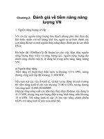
Hardware solution- Timer
13
Timer1 registers
•
TMR1, which contains the 16-bit counter value.
•
T1CON, which controls activation and the operating mode of the
timer.
•
PR1, which can be used to produce a periodic reset of the timer
•
(not required here).
•
We can clear the TMR1 register to start counting from zero.
•
TMR1 = 0;
•
Then we can initialize T1CON so that the timer will operate in a
simple confi guration where:
•
Timer1 is activated: TON = 1
•
The main MCU clock serves as the source (Fosc/2): TCS = 0
•
The prescaler is set to the maximum value (1:256): TCKPS = 11
•
The input gating and synchronization functions are not required,
since we use the MCU internal clock directly as the timer clock:
TGATE = 0, TSYNC = 0
•
We do not worry about the behavior in IDLE mode: TSIDL = 0
(default)
14
1. #include <p24fj128ga010.h>
2. #define DELAY 16000
3. main()
4. {
5. // init the control registers
6. TRISA = 0xff00; // PORTA pin 0 7 as output
7. T1CON = 0x8030; // TMR1 on, prescaler 1:256 Tclk/2
8. while( 1) // main application loop
9. {
10. PORTA = 0xff; // turn pin 0-7 on and wait for ¼ second
11. TMR1 = 0; // restart the count
12. while ( TMR1 < DELAY)
13. {
14. // just wait
15. }
16. PORTA = 0x00; // turn all pin off and wait for ¼ second
17. TMR1 = 0; // restart the count
18. while ( TMR1 < DELAY)
19. {
20. // just wait
21. }
22. } // main loop
23. } // main
15
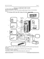
Logic Analyzer
•
The logic analyzer gives you a graphical and
extremely effective view of the recorded values
for any number of the device output pins, but it
requires a little care in the initial set-up.
•
Before anything else, you should make sure that
the Tracing function of the simulator is turned
on.
1. Select the “Debug→Settings” dialog box and
then choose the Osc/Trace tab.
2. In the Tracing options section, check the Trace
All box.
3. Now you can open the Analyzer window, from
the “View→Simulator” Logic Analyzer menu.
16
17
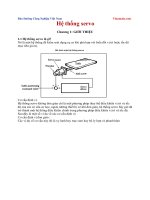
4. Then click on the channel button, to bring
up the channel-selection dialog box.
18
5. From here, you can select the device output
pins you would like to visualize.
In our case, select RA0 and click “Add =>”.
6. Click on OK to close the channel-selection
dialog box.
19
20
Post-flight briefing
•
MPLAB C30 compiler deals with program termination.
•
For the first time, we gave our little project a bit of
structure—separating the main() function in an
initialization section and an infinite loop. To do so, we
learned about the while loop statements and we took the
opportunity to touch briefly on the subject of logical
expressions evaluation.
•
We closed the lesson with a final example, where we used
a timer module for the first time and we played with the
Logic Analyzer window to plot the RA0 pin output.
21
Exercises
1. Output a counter on the PORTA pins
instead of the alternating on and off
patterns.
2. Use a rotating pattern instead of
alternating on and off.
3. Readding at home CHAPTER 3: More
pattern work, more loops: Do loop, for
loop, variable, array (pg 29-40)
22
What is next?
•
CHAPTER 4: NUMBERS
–
List all number types?
•
CHAPTER 5: Interrupts (pg 53 - pg68)
–
What is it? (what for?)
–
How does it work?
–
Benefits? Problems?