Hệ thống nhúng - Chương 3 doc
Bạn đang xem bản rút gọn của tài liệu. Xem và tải ngay bản đầy đủ của tài liệu tại đây (254.5 KB, 21 trang )
1
Hệ thống nhúng
Thạc sĩ Lê Mạnh Hải
Embedded Systems
2
Lesson 3 : NUMBERS
Flight plan:
•
In this lesson we will review all the numerical data
types offered by the MPLAB® C30 compiler.
•
We will learn how much memory the compiler
allocates for the numerical variables and we will
investigate the relative efficiency of the routines
used to perform arithmetic operations by using the
MPLAB
•
SIM Stopwatch as a basic profiling tool. This
experience will help you choose the “right”
numbers for your embedded-control application,
understanding when and how to balance
performance and memory resources, real-time
constraints and complexity.
3
Preflight checklist
•
MPLAB IDE, Integrated Development
Environment
•
MPLAB SIM, software simulator
•
MPLAB C30 compiler (Student Version)
4
The flight
1.MPLAB C30 User Guide
5
The flight
unsigned long i,j,k;
main ()
{
i = 0x1234; // assign an initial value to i
j = 0x5678; // assign an initial value to j
k = i * j; // perform the product and store the result in k
}
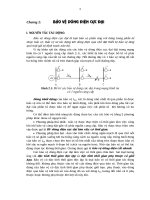
6
Assembly code
7
On optimization (or lack thereof)
•
In fact, the compiler does not see things this clearly—its
role is to create “safe” code, avoiding (at least initially)
any assumption and using standard sequences of
instructions.
•
Later on, if the proper optimization options are enabled,
a second pass (or more) is performed to remove the
redundant code.
•
During the development and debugging phases of a
project, though, it is always good practice to disable all
optimizations as they might modify the structure of the
code being analyzed and render single-stepping and
breakpoint placement problematic.
8
Testing
•
Set the cursor on the first line containing the initialization of the first
variable, and perform a Run To Cursor command to let the program
initialize and stop the execution just before the first instruction we
want to observe.
•
Open the Watch window (“View→Watch”) and select WREG0 in the
SFR selection box, then click on the “Add SFR” button.
•
Repeat the operation for WREG1.
•
Select “i” in the symbol selection box, and click on the “Add Symbol”
button.
•
Repeat the operation for j and k.
•
Use the “Step Over” function to execute the next few program lines,
observing the effects on the registers and variables in the Watch
window. As we noted before, when the value of a variable in the
Watch window changes, it is conveniently highlighted in red.
9
Post-flight briefing
•
In this lesson, we have learned not only what data types are
available and how much memory is allocated to them, but
also how they affect the resulting compiled program—
code size and the execution speed.
•
We used the MPLAB SIM simulator Stopwatch function to
measure the number of instruction cycles (and therefore
time) required for the execution of a series of code
segments.
•
Some of the information gathered will, hopefully, be useful
to guide our actions in the future when balancing our needs
for precision and performance in embedded-control
applications.
10
Interrupts
•
What is Interrupts?
•
Why does ES need more and more
Interrupts?
•
How does Interrupts work?
•
How can we control Interrupts?
11
Flight plan
•
How the MPLAB® C30 compiler allows us to
easily manage the interrupt mechanisms offered
by the PIC24 microcontroller architecture.
•
After a brief review of some of the C language
extensions and some practical considerations, we
will present a short example of how to use the
secondary (low-frequency) oscillator to maintain a
real-time clock.
12
Preflight checklist
•
MPLAB IDE,
•
MPLAB C30 compiler and the MPLAB SIM
simulator.
•
Use the “New Project Set-up” checklist to
create a new project called “Interrupts” and
a new source file similarly called
“interrupts.c”.
13
The flight
•
The PIC24 architecture provides a rich interrupt system that
can manage as many as 118 distinct sources of interrupts.
•
Each interrupt source can have a unique piece of code, called
the Interrupt Service Routine (ISR) directly associated via a
pointer, also called a “vector,”
•
Interrupts can be completely asynchronous with the execution
fl ow of the main program. They can be triggered at any point
in time and in an unpredictable order. Therefore, the goal is to
minimize the interrupt latency, defined as the time between the
triggering event and the execution of the fi rst instruction of
the Interrupt Service Routine (ISR).
•
In the PIC24 architecture, the latency is not only very short
but it is also fixed for each given interrupt source—only three
instruction cycles for internal events and four instruction
cycles for external events.
14
PIC24F Interrupt
• Up to 8 processor exceptions and software traps
• 7 user-selectable priority levels
• Interrupt Vector Table (IVT) with up to 118
vectors
• A unique vector for each interrupt or exception
source
• Fixed priority within a specified user priority level
• Alternate Interrupt Vector Table (AIVT) for debug
support
• Fixed interrupt entry and return latencies
15
Interrupt Vector Table (IVT)
MPLAB C30 compiler can automatically associate
interrupt vectors with “special” user-defined C
functions as long as a few limitations are kept in
consideration, such as:
•
They are not supposed to return any value (use
type void).
•
No parameter can be passed to the function (use
parameter void).
•
They cannot be called directly by other functions.
•
Ideally, they should not call any other function.
16
Interrupt service
1. void __attribute__ (( interrupt)) _T1Interrupt ( void)
2. {
3. // interrupt service routine code here
4. } // _InterruptVector
17
Interrupt service
1. void _ISR _T1Interrupt (void)
2. {
3. // interrupt service routine code here
4. } // _InterruptVector
18
external sources
•
5 × External pins with level trigger detection
•
22 × External pins connected to the Change Notifi
cation module
•
5 × Input Capture modules
•
5 × Output Compare modules
•
2 × Serial port interfaces (UARTs)
•
4 × Synchronous serial interfaces (SPI and I2C™)
•
Parallel Master Port
19
internal sources
•
5 × 16-bit Timers
•
1 × Analog-to-Digital Converter
•
1 × Analog Comparators module
•
1 × Real-time Clock and Calendar
•
1 × CRC generator
20
Exercises
1. Write a program that uses Timer2 as a stopwatch for
real-time performance measurements. If the width of
Timer 2 is not sufficient: use the prescaler (and lose
some of the lsb), or use Timer2 and Timer3 joined in the
new 32-bit timer mode.
2. Test the relative performance of the division for the
various data types.
3. Test the performance of the trigonometric functions
relative to standard arithmetic operations.
4. Test the relative performance of the multiplication for
complex data types.
21
What is next?
•
CHAPTER 5: Interrupts (pg 53 - pg68)
–
Nesting of interrupts?
–
A template and an example for Timer1 interrupt
–
A real example with Timer1
–
Testing the Timer1 interrupt
–
The secondary oscillator
–
The real-time clock calendar (RTCC)
–
Managing multiple interrupts
•
PIC24F family manuals. Section 8. Interrupts
•
How to get them?
/>IdcService=SS_GET_PAGE&nodeId=2575