BÀI GIẢNG: HỆ THỐNG PHANH pdf
Bạn đang xem bản rút gọn của tài liệu. Xem và tải ngay bản đầy đủ của tài liệu tại đây (1.01 MB, 59 trang )
Diagnosis Technician >> Brake >> Brake System
TRƯỜNG ĐẠI HỌC SƯ PHẠM KỸ THUẬT TP.HCM
KHOA CƠ KHÍ ĐỘNG LỰC
HỆ THỐNG PHANH
BRAKE SYSTEM
Diagnosis Technician >> Brake >> Brake System
CÔNG DỤNG
Tạo ra lực cản ở bánh xe để:
- Giảm tốc độ xe
- Dừng xe
- Hoặc đậu xe
Diagnosis Technician >> Brake >> Brake System
PHÂN LOẠI
@ Theo chức năng:
- Phanh chính
- Phanh đậu xe
@ Theo dẫn động phanh:
- Phanh cơ khí
- Phanh thủy lực
- Phanh khí nén
- Phanh thủy khí
Diagnosis Technician >> Brake >> Brake System
PHÂN LOẠI
@ Theo cơ cấu phanh:
- Phanh trống (guốc)
- Phanh đĩa
- Phanh đai
@ Theo trợ lực phanh:
- Trợ lực bằng chân không
- Trợ lực bằng thủy lực
- Trợ lực bằng khí nén
Ngoài ra, còn có:
- Phanh bằng động cơ
- Phanh khí xả
Diagnosis Technician >> Brake >> Brake System
YÊU CẦU
- Lực phanh lớn và tác dụng nhanh (nhạy), có khả năng dừng xe
gấp với thời gian và quãng đường phanh ngắn nhất
- Hoạt động êm dịu, tính ổn định chuyển động của xe khi phanh cao
- Lực phanh phân phối ở các bánh xe theo qui luật phân bố tải
trọng
- Lực tác dụng lên bàn đạp phanh nhẹ nhưng có khả năng tạo ra
lực phanh lớn ở các cơ cấu phanh
- Lực phanh ở các cơ cấu phanh phải tỉ lệ với lực tác dụng lên bàn
đạp phanh
- Thoát nhiệt tốt, có khả năng hoạt động liên tục trong khoảng thời
gian dài
- Dễ kiểm tra, sửa chữa
Diagnosis Technician >> Brake >> Brake System
HỆ THỐNG PHANH THỦY LỰC
@ Các bộ phận chính:
- Bàn đạp phanh
- Bộ trợ lực phanh
- Xy lanh chính
- Đường ống dẫn động dầu
- Các van phân phối và điều chỉnh lực
phanh
- Cơ cấu phanh (trống, đĩa)
Diagnosis Technician >> Brake >> Brake System
HỆ THỐNG PHANH THỦY LỰC
@ Bố trí mạch dầu phanh:
- Mạch thường (kiểu xe FR)
- Mạch chéo (kiểu xe FF)
-
Diagnosis Technician >> Brake >> Brake System
XY LANH CHÍNH
@ Theo chức năng:
- Phanh chính
- Phanh đậu xe
@ Theo dẫn động phanh:
- Phanh cơ khí
- Phanh thủy lực
- Phanh khí nén
- Phanh thủy khí
Diagnosis Technician >> Brake >> Brake System
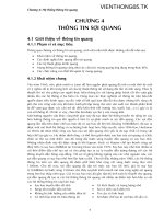
Brake System
(1/1)
6. Parking brake
5. Disc brake
1. Brake pedal
2. Brake booster
3. Master cylinder
4. Proportioning valve
(1) Disc brake
(2) Disc brake
Diagnosis Technician >> Brake >> Brake System
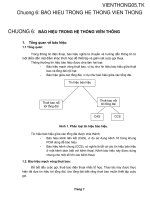
Master Cylinder
General & Construction
(1/3)
1.General/2.Construction
Minimum
(5)
Rubber piston
cups
(7) Fluid level sensor
(6) Reservoir tank
(1) No.1 piston
(2) No.1 return spring
(3) No.2 piston
(4) No.2 return spring
Diagnosis Technician >> Brake >> Brake System
Master Cylinder
General & Construction
(2/3)
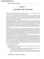
3. Principles
Fulcrum
Principle of the lever
Wheel cylinder
The principle of the lever is applied by the brake pedal as follows.
A
B
F1 A = F2 B F2 = F1
F1: Pedal force
F2: Push rod output force
A1: Distance from center of brake pedal to
fulcrum
B: Distance from push rod to fulcrum
Operating force:
Push rod
b
F2
A
B
F1
a
Pascal’s law
Master cylinder
5 cm
2
10 cm
2
2000 N
8 cm
40 cm
400 N
Same pressure
(2000 kPa)
4000 N
2000 N
1000 N
10 cm
2
20 cm
2
b B A B
a A B A
a: Amount of movement of pedal edge
b: Amount of movement of push rod
Amount of movement:
= a = b b = a
Diagnosis Technician >> Brake >> Brake System
Master Cylinder
General & Construction
(3/3)
4.Types of brake lines
Front
FR vehicle
FF vehicle
Front
Diagnosis Technician >> Brake >> Brake System
Master Cylinder
Operation
(1/4)
1.Normal operation
No.2 return spring
FF vehicle
to front side
No.1 return
spring
to Rear side
No.2 piston
Compensating port
Inlet port
No.1 piston
No.1 piston cup
Stopper bolt
No.2 piston cup
Diagnosis Technician >> Brake >> Brake System
Master Cylinder
Operation
(2/4)
Brake pedal depressed (1)
to Front side
to Rear side
No.2 piston
Compensating port
Piston cup
No.1 piston
Brake pedal depressed (2)
Diagnosis Technician >> Brake >> Brake System
Master Cylinder
Operation
(3/4)
Brake pedal released (1)
to Front side
to Rear side
Inlet port
Piston cup
Compensating port
Orifices
Brake pedal released (2)
Diagnosis Technician >> Brake >> Brake System
Master Cylinder
Operation
(4/4)
to Front side to Rear side
No.1 piston
Contact
No.2 piston
Diagnosis Technician >> Brake >> Brake System
Master Cylinder
Operation
(4/4)
to Front side to Rear side
No.1 piston
Piston contacts wall
No.2 piston
Diagnosis Technician >> Brake >> Brake System
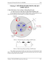
Brake Booster
General & Construction
(1/1)
(12) Constant pressure chamber
(5) Diaphragm
(3) Booster piston
(7) Valve body
(8) Reaction disc
1.General/
2.Construction
(13) Check valveVacuum
Brake master cylinder
(10) Body seal
(2) Push rod
(4) Booster body
(6) Diaphragm spring
(11) Variable pressure chamber
Air
(1) Valve operating
rod
(9) Air cleaner
(10) Body seal
HINT: Tandem brake booster
Diagnosis Technician >> Brake >> Brake System
Brake Booster
Operation
(1/1)
Booster piston
Control valve
Diaphragm
spring
Vacuum valve (opened)
Piston
1.Brakes not applied
Valve operating rod
Variable pressure
chamber
Constant pressure
chamber
Air valve
(closed)
Variable pressure
chamber
Passage B
Air valve return
spring
Air cleaner
element
Control valve
Control valve spring
Valve operating
Constant pressure
chamber
Valve body
Passage A
Diagnosis Technician >> Brake >> Brake System
Brake Booster
Operation
(1/1)
Booster piston
Control valve
Piston
2.Brakes applied
Valve operating rod
Variable pressure
chamber
Constant
pressure
chamber
Air valve
(opened)
Variable pressure
chamber
Control valve spring
Air cleaner
element
Control valve
Control valve
spring
Valve operating
rod
Constant pressure
chamber
Control valve
Passage A
Vacuum valve (closed)
Passage B
Air valve
(closed)
Air
Passage B
Booster push
rod
Diaphragm spring
Diagnosis Technician >> Brake >> Brake System
Brake Booster
Operation
(1/1)
Booster piston
Control valve
Piston
3.Holding state
Valve operating rod
Variable pressure
chamber
Constant pressure
chamber
Variable pressure
chamber
Control valve spring
Valve operating
rod
Constant pressure
chamber
Control valve
Diaphragm spring
Vacuum valve
Air valve
(closed)
Stopped
Diagnosis Technician >> Brake >> Brake System
Brake Booster
Operation
(1/1)
Booster piston
Control valve
Piston
4.Maximum boost
Valve operating rod
Variable pressure
chamber
Constant
pressure chamber
Variable pressure
chamber
Control valve spring
Valve operating
rod
Constant pressure
chamber
Control valve
Diaphragm spring
Vacuum valve
Air valve
(opened)
Booster
push rod
Air
Diagnosis Technician >> Brake >> Brake System
Brake Booster
Operation
(1/1)
Booster piston
Control valve
Piston
5.Non-vacuum
condition
Valve operating rod
Variable pressure
chamber
Constant
pressure chamber
Variable pressure
chamber
Valve body
Valve operating rod
Constant pressure
chamber
Control valve
Diaphragm spring
Vacuum valve
Air valve
Booster
push rod
Valve stopper key
Reaction disc
Diagnosis Technician >> Brake >> Brake System
Brake Booster
Reaction mechanism
(1/1)
Valve body
Air valve
1.General/2.Operation
Reaction disc
20 N
(to Air valve)
80 N
(to Valve body)
Booster
push rod
100 N
1cm
2
(20N)
4cm
2
(80N)
Diagnosis Technician >> Brake >> Brake System
Brake Booster
Gap Adjustment of Push Rod
(1/1)
Choke applied
SST
Thickness
gauge
BRAKE BOOSTER ADJUSTMENT
•Thickness Gauge(0.2mm or 0.008inch)
and Special Service Tool(SST 09737-
00010)are required to check and adjust
the push rod length.
• See Repair Manual for details.
Accessory tool
SST
STT 09737-00010