21st Century Manufacturing Episode 2 Part 8 pptx
Bạn đang xem bản rút gọn của tài liệu. Xem và tải ngay bản đầy đủ của tài liệu tại đây (498.37 KB, 20 trang )
334
Plastic-Products Manufacturing and Final Assembly Chap. 8
8.3 PROCESSING OF PLASTICS I: THE INJECTION MOLDING
METHOD
8.3.1
Overview
Injection molding is a key production method for the casings of consumer products.
It is cheap, reliable, and reduces the device's weight compared with metals. The ST
Microelectronics' 'IouclrCblpt'" (the case study in Chapter 2) and the InfoPad cas-
ings (the case study in Chapter 6) were made in this manner. A very wide array of
consumer products ranging from toys to telephones to automobile parts is also made
through this process.
In Figure 8.4,some general features of the mold are shown. A simple bucket or
cuplike component could be made in the gap between the core and the cavity shown
at the bottom right. In this case the paning plane, shown on the bottom left, could be
at the lip of the bucket. For other products the parting plane might be less conve-
niently located. Thus, a ridge is often visible around plastic toys and simple appli-
ances where the parting plane has been located Further finishing by hand might be
desirable for such parts.
Hand finishing might also be needed (a) for the injection's "gate marks" that
maybe visible as tiny "pimples" on the surface of a part and (b) for the "ejector-pin"
marks that for a relatively small object like a cellular phone casing are usually about
6 mm (about 0.25inch) in diameter. The reader might be interested in picking up any
familiar plastic consumer product and searching for these inevitable markings. How-
ever, these are often located in noncosmetic areas of the part, because of the cost
involved in finishing operations. Not surprisingly, they are often found on the bottom
or base of the object.
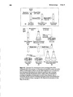
Injection molding is shown in Figure 8.5.Pellets of the desired thermoplastic
are loaded into the hopper on the right side and heated as they are pushed by a screw
1
Parting
direction
z
x~Yx
-y
·"2
Principal
directions
FJeure 8.4 &sic meld
description,
including slider for an
'Ullden:ui.
Cavity
direction
Und:n::Ul
Molding
Parting plane
Pull-out
Cavity
8.3 Processing of Plastics I: The Injection Molding Method
335
(,)
Hopper
Mo,,",
half
M~ld
Y
r
Clamp
I
I
Injection
Gate
(bl
(dl
Molded part
F1guJe 8.S Injection molding with reciprocating-screw machine.
through heating zones. This melted and mixed material is forced through a nozzle
into the mold by a hydraulic ram. The thermoplastic then cools, sets, and hardens in
the mold. Once the two halves of the mold have been separated, the ejector pins
facilitate "popping the part" out of the lower part of the mold. The process is now
reviewed in more detail.
Nozzle
injection
machine
Sprue bush
Filled
,Sprue half
Impression
Back-flow
atou valve
N?zzle
r
Hydraulic motor
'Sprue
'Sprue
bush
Gate land
-Ccld slug
"Runner
Branch runner
Sprue
Gate .
Parting·
surface
33.
Plastic-Products Manufacturing and Final Assembly Chap. 8
8.3.2 The Reciprocating-Screw Machine
The reciprocating-screw machine is the most used machine in industry. It is
shown in the open position in Figure 8.5a. Below the machine is a single-cavity
mold and a multiple-cavity mold. Note that the machine is horizontally constructed
and operated. Thus the mold is effectively laying on its side in comparison with
Figure 8.4.
In Figures 8.5b and 8.5e the cavity is on the right and the core is on the left.
Molten plastic is shot into the mold from the nozzle of the reciprocating-screw
machine and into the sprue of the mold. If there are multiple cavities (Figure 8.5d),
the sprue feeds the runners and gates.
The barrel of the machine is heated, and as the screw pushes the pellets tor-
ward, there is additional heating from the mechanical pulverizing effect. In fact the
machine is designed to operate in two distinct phases:
• Step 1,plasticizing the thermoplastic: the combined action of the heaters and
screw feed creates a metered volume of liquid polymer that arrives at area Y,
just behind the nozzle. Since the nozzle is small in diameter, it is sealed shut at
this point by a cold slug of plastic from the previous shot.
• Step 2,injection into the mold: the screw action stops, and the whole stationary
screw is now used as a ram to force the liquid out of the nozzle, through the
sprue, and into the mold. Immediately before the ram action, the mold has
been closed so that the liquid polymer fills the impressions shown as the dark
areas in Figures 8.5b and 8.5L:.
It should also be noted that a nonreturn valve just behind the Tamhead pre-
vents the liquid from moving backward into the screw channels. Following this two-
step process several things happen in unison. The part begins to cool down, and after
a sufficient waiting period, the mold can be opened to eject the part. To reduce the
cooling period, the mold isactively cooled by water lines. But during the cooldown,
the screw can begin to turn again to collect its next shot of polymer pellets and move
back to create space in position Y for the next shot.
8.3.3
Computer Aided Manufacturing
McCrum, Buckley, and Bucknall (1997) describe the research into equipment and
control design in recent years. The screw has the triple function of transporting the
pellets, compressing and melting them with help from the heater zones, and then,
during the ramming action, having enough strength to pump the melt through the
nozzle into the die.The clearance between the barrel and the flat lands of the screw
flights is only 10-
2
mm, demanding that the machine screw and the barrel be made
from hardened steel with wear resistant coatings. Internal pressures of 100 Mpa are
typical.
CNC controllers are used to monitor various sensors in the system and to
adjust the various parameters shown in Figure 8.6.The key features include:
•Thermocouples for the temperatures of the barrel, nozzle, and mold
• Pressure sensors on the screw/ram
8.3 Processing of Plastics I: The Injection Molding Method
MoldprasureooDtrol
Closed loop control of mold
pressure during packing
phase to ensure consistent
part density. Measured mold
pressure iscompared to
desired value and hydraulic
pressure is changed
accordingly.
CushionfshotJize
eontrol
Automatically maintains
a constant volume of
material in front of the
screw after the mold is
fiUed.This ensures that
the material in the mold
is subjected to the
proper pressure during
the packing phase and
a1sothat there is
sufficient material to
properly pack the parts.
337
Velodty to pressure oontrol
Transition from velocity program to
ram pressure control phase is
automatically activated using
measured machine or plastic
conditions. Transfer mode is
selectable from mold pressure,
hydraulic pressure, or ram position.
RampressureooDb:oI
Initiated after the
velocity phase to
provide dosed loop
control of hydraulic
pressure during pack
hold and screw recovery
phases. Maintains
controlled pressure
during these critical
phases despite changes
in oil temperature,
valve leaking, or
system Loading.
Proxnunmed injection
(velocity control)
Closed loop control of
ram speed as plastic is
being injected into the
mold. Separate
velocity steps can be
programmed to occur
anywhere within the
active ram stroke.
F1gufe
tl6
Control of injection molding (courtesy of Barber-Colman DYNA
Products)
•Pressure sensors monitoring the pressure in the mold
• A screw position sensor (potentiometer or LVDT), which also measures
velocity during the ramming step
The controller is used to optimize the cycle and to pack and hold the polymer in the
mold under the continuing pressure of the ram.
Two
methods for doing this are
described in Section 8.3.5.
8.3.4
Behavior of the Polymer inside the Mold during the
Filling Stage
When a polymer cools in the die cavity,
it
shrinks dramatically and grips the sides of
the core walls. During the milling operations (Chapter 7) to create the molds, these
-Moldpressuresensor
Position sensor
Hydraulic
sensor.?"
338
Plastic-Products Manufacturing and Final Assembly Chap, 8
walls must therefore be tapered to allow easier part ejection. The volume contrac-
tions of a polymer between its liquid temperature and room temperature are of the
order of 10% at normal atmospheric pressure. This presents another problem for the
manufacturing of plastics because voids and sink marks would occur
if
the polymer
were allowed to shrink this much without special controls. These voids can reduce
the mechanical properties and cause cosmetic imperfections.
Figure 8.7 from McCrum and colleagues (1997) shows how this volumetric
shrinking isaddressed. Lines a,
b,
and c in the diagram represent isobars of increasing
pressure, with line c being the highest. The details are explained inthe next paragraph.
The cycle is as follows:
• At the highest temperature and specific volume (V A) the liquid plastic is first
pressurized, in the mold, to a pressure of approximately P
=
10
3
atmospheres.
This leads to a volume decrease of about 10% (i.e.,A
taB
between lines
a
and
c).
In Equation 8.2 below,
K
is the bulk modulus, which is 1 GPa, typical of most
liquids:
6.V P
10
3
X 1.01 X 10
5
-y-
=
K
= ~ =
0.101 (8.2)
• In other words when the liquid polymer is rammed in at this pressure, and the
mold is 100% filled, it will contain 10% more polymer than if it were filled at
1 atmosphere.
• In the next phase, between Band C, the part in the mold cools under pressure
(value, C), and the ram keeps additional liquid flowing into the mold to com-
pensate for contractions.
• At point C, the gate freezes over, sealing the mold and preventing further
packing.
• Between C and D, the plastic cools at constant volume
(V
D)
under decreasing
pressure until atmospheric pressure returns again at position D.
v,·
,
,
,
I
Glassy
Room T
g
temperature
Increasing
pressure
Viscous
Temperature
Figure 8.7 Liquid polymer follows the path
A to B as a pressure of approximately io'
atmospheres is applied. The liquid is
"packed" between
B
and C.At point C, the
gate freezes over. Between C and D, the
plastic cools at constant volume
(V
D)
(adapted from McCrum, Buckley, and
BucknaU,l997).
Liquid
Packing
8.3 Processing of Plastics I: The Injection Molding Method
339
•From
D
to
E
the mold cools naturally and undergoes normal thermal contrac-
tion. If the polymer had been allowed to cool naturally, the free thermal
shrinkage would have been
=
(1 - V ElVA)
=
10% to 15%. However, because
of the pressurized cooling cycle,the contraction is
=
(1-
VEIVD)
=
1%.
The maximum available clamping force is one of the key specifications in
designing and costing equipment. Other main specifications include: (a) shot size,
which is expressed as a mass equivalent volume of polystyrene, and (b) ejection
stroke, which limits the maximum part depth that can be molded.
8.3.5 Controlling the Polymer Cool down
There are two main methods to control the pressurized cooldown in Figure 8.7.These
are summarized in the next two diagrams from the Barber-Colman Company. Actu-
ally,in both cases, Step 1,the mold filling with the ram, is similar:
• Step 1,for filling: a sequential velocity profile isprogrammed in, shown by the
steps on the left of Figure 8.8. The velocity is high at first to accelerate the
liquid polymer into the mold, but then it decreases as filling gets completed.
ven
Mold fiUingphase
+~Ram
pressure control phase
Under control of programmed I
I I
injection } Pack_Hold +k-Back
"
,
in
I Pressure
i
: :
IVel
s
TIm,
Position 2
, Fill
i
Pack
iHOld
~./"t'ss,
:1
~lire
Screw
rotate
Position)
Position 4
PositionS
Flame
U
Injection molding cycles.The upper figure
ill
ram pressure controlled,
and the lower figure is mold pressure controlled (courtesy of Barber-Colman
DYNA Products).
Velocity
Vel 4
340
Plastic-Products Manufacturing and Final Assembly Chap. 8
• Step 2, alternative 1 to packing, for the packing and holding phase (along A to
B
to
C
in Figure 8.7): the ram pressure is used to control the process. The pres-
sure sensor on the ram is used to monitor and control the highest pressure
during packing the mold to its desired mass. The system then transfers to the
lower holding pressure until the gate freezes. and then after a set time the
screw/ram rotates and moves back, shown on the extreme right of the figure.
•Step 2,alternative 2 to packing: amore direct method isto install a pressure sensor
in the mold cavity.Figure 8.8 shows that this allows a more graceful release of the
mold pressure and a direct measure of the processes inside the cooling mold.
8.3.6
Ejection and Resetting Stage
In the ejection and resetting stage, the cavity and core are separated as the mold is
opened, and the ejector pins "pop" the part away from the die surface. The schematic
of a "two-plate mold" shown in Figure 8.9 is from Glanvill and Denton (1965). It indi-
cates that real production molds are rather more substantial than might be suggested
by the earlier figures showing general nomenclature. In fact, even Figure 8.9 is a
more simplified view of a mold. Classical texts in this area, such as that by Pye (1983)
and by Glanvill and Denton (1965), show that many extra alignment pins and
backing plates are needed beyond those shown in the schematic. The extra bulk. sup-
port blocks, ejector plates, and damping plates reflect the facts that molding pres-
sures are high and production runs are long (e.g., 10,000 to 10,000,000 parts). Thus a
substantial device is needed so that the ejector pins and moving parts do not wear
out. The downside is that molds open relatively slowly with hydraulic or mechanical
actuators, and it takes care to lift the parts out of the cavity after the ejector pins have
pushed it off the core plate (center of Figure 8.9). As much ejection area as possible
is desirable to minimize part distortions and to minimize cycle time.
8.3.7 Positioning the Gate
Figure 8.10a shows some typical gate designs, and Figure
8.1De
indicates the pre-
ferred sprue/gate for a cup shape. The gate is a very small orifice, and as the liquid is
forced through, additional shearing causes a temperature rise of about 20°C,which
is beneficial in mold filling. At a later stage, the small orifice is beneficial again
because the polymer first freezes at the gate, thereby separating the molded part
from the material in the barrel. The correct gate design is also the key to efficient
mold filling, as shown on the right of Figure 8.10c.
Finally, the gate should be placed in a position that creates an acceptable part.
Key design issues include:
• Positioning the gate on a surface that is noncosmetic. For consumer electronics
this usually means
it
will be on the inside of the casing. In other situations it
should be inexpensive to remove or present no finishing problems.
•Avoiding placing the gate near a stress concentration point of the product.'
8.3 Processing of Plastics I: The Injection Molding Method 341
Sprue bushing
Clamping plate
Cavity plate
Core plate
Support plate
Spacer blocks
Ejector retainer plate
Ejector plate
Rear damping plate
F1pre 8.9 Two-plate mold based on G1anvill and Denton (1965)
Schematic courtesy of Boothroyd et al.(1994) .
•Positioning the gate where
it
will facilitate air expulsion as the injected liquid
cools down.
•Avoiding the formation weld lines at cosmetic or stress critical areas.
The reader might be wondering how the air escapes as the ram fills the mold.
In general, minute vents are installed on the parting plane, allowing the air to
escape. Air can also be made to escape around the ejector pins.The position ofthe
gate relative to these minute vents is important: there should be an easy flow of air
from the gate-location side of the mold to the vent positions. If the air is not prop-
erly vented, it will become superheated, because of the high pressures involved,
and scorch the part.
Locating ring-
Ejector pins
342
Plastic-Products Manufacturing and Final Assembly Chap. 8
~~~G
Ring gate Fan gate Diaphragm gate Sprue gate
:3=
O::u
a=
~~ ~~e ~~ ~~
(a)
Weld line
(b>
(0)
Figure 8.10 (a) Various gate designs in the top figure. The lower figure shows
(b) an inefficient gating method and (c) the preferred method (on the right) to fill
JI cup (lIdllpt"d fmm JrT Jlnd Pye)
8.3.8 Design Guides for the Part to Be Molded
The design of the mold requires great experience to account for the shrinkage' of the
thermoplastic during cooling, the draft angles that must be added to vertical walls so
that the part can be ejected, and the location of the parting plane.
Some other key design guides are shown in Figure 8.11. This figure is taken
from Magrab (1997) and is based on the guides by Bralla (1998) and
by
Niebel,
Draper, and Wysk (1989). The guides recommend:
• The avoidance of undercuts for simplification of ejection
• Uniform wall thickness for obtaining uniform shrinkage and avoiding warpage
• Dual diameters for deep holes to stiffen core pins under pressure and for
cooling
"Iypical shrinkages between the CAD geometry and the final part are 1% to 2%. A typical draft
angle of 1 to 5 degrees is needed on a CAD design for a part that will be injection molded. These values
will depend on the plastic and the texture used. Rather than quote values that may date quickly, for exten-
sjvelistings,thereaderisreferredto< __ ~>.
Runner
Sprue gate
Gate
Representative Design Guidelines for Injection Molding
8.3 Processing of Plastics I: The Injection Molding Method
BetterGuideline
343
Maintain uniform wall thickness and provide for
graduaJ changes in wall thickness
For a deep blind hole, use a stepped diameter
Maintain uniform wall thickness in thermoset parts.
A bead at the parting line facilitates removal of mold
flash,
Use decorative designs to conceal shrinkage.
Avoid undercuts and variation in wall thickness.
Deliberately offset side walls to hide defects caused
when mold halves do not line up properly.
Minimum spacing for holes and sidewalls.
Minimum distance between a hole and the edge of the
part.
AA
q
l
IT1
B B8
o
iiJ
U E]
E3 B
Jm
bit?
B
EJ
Fieme 8.11 Design guides for plastic injection molds. Reprinted with permission from
Integrated Product and Process Design and Development by E. B. Magrab. Copyright CRC
Press, Boca Raton, Florida.
•Minimum spacing distances from holes to holes and from holes to walls to
ensure that the mold fills correctly and uniformly in the spaces between features
• Cavity shapes that reduce "flash" at the parting line
•The use of decorations to divert the eye from difficult-to-mold areas (One
"trick," for example, is to scribe shallow circles around the gate position.After
fum
344
Plastic-Products Manufacturing and Final Assembly Chap. 8
Holes produced
by core rods
(h)
•
••
,
.
o
@
@.
F1Jure &12 Cantilever snap-fit assembly made possible in the injection molding process:
(a) the direction of the arrows shows where core rods would be puUed down after molding to
create the required undercuts; (b) the arrows show the direction of side pullouts. On the right
is a Digital Corporation mouse that was redesigned with the Boothroyd and associates DFA
methods-the snap fits are shown in the lower subassembly (both diagrams courtesy of
Boothroyd et al., 1994).
molding the user/consumer sees the kind of pattern seen around a stone
thrown in a pond. It seems a deliberate cosmetic design feature to the unsus-
pecting eye,but actually it camouflages the rougher gate nipple.)
•The use of textured molds to create a "fine-orange-peel-like" surface that
camouflages shrinkage and other blemishes
8.4 Processing of Plastics II: Polymer Extrusion
345
•Increasing offsets at parting lines rather than trying to make them line up per-
fectly (Thisisa well-knowntrick in carpentry-a bigger"setback" looksdelib-
erate, whereas a small one looks like a mistake.)
The relatively lowYoung'smodulus ofplasticscompared with metals also facil-
itates design with snap fits. In Section 8.7, the famous story of IBM's ProPrinter
redesign willbe mentioned. IBM carried out a full redesign of its standard printer,
reduced the "part count," and used snap fits as much as possible rather than screws.
This had a great impact on the part count, which was reduced from 152to 32. Con-
sequently the assembly time, also related greatly to the thermoplastic snap fits,was
reduced from 30 to 3 minutes (see Dewhurst and Boothroyd, 1987).Figure 8.12
showsmold designs that create such snap-fit cantilevers. In the upper diagram, core
rods in the mold are movable and leave the plastic projections freestanding and thus
able to exhibit flexure. In the lower diagram, side-pullout pieces of metal insert
create the undercuts beneath the plastic projections.
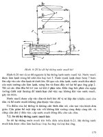
8.4 PROCESSING OF PLASTICS II: POLYMER EXTRUSiON
In the bulk manufacturing of plastic products simpleextrusion is the most common
process. The products include tubes, plastic pipes for plumbing, window frame
moldings, and insulated wire for electrical use. The polymer passes through the
barrel's heated zones and is also plasticized by the screwing action. At the die
mouth, liquid product is extruded through the preshaped die shown at the left of
Figure 8.13.
Note also that the internal diameter of the screw is less at the back end near
the hopper than at the front end. This is because compressed solid pellets pack
irregularly and have a larger volume than the same mass of liquid. However, since
the rate of mass flow must be constant at any plane in the screw mechanism, the
area of the screw channel must decrease asthe polymer transforms from solid pel-
lets to liquid.
Hopper
Figure8.13 Extrusion with the die on the left.
Perforated
breaker plate
Barrel heater
Screw
Control thermocouples Flighl
F~d
pocket.
Meterlna sectiort
Compression section Feed section
Barrel
Die
346
Plastic-Products Manufacturing and Final Assembly Chap.8
A
c
D
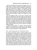
Figure 8.14 Blow molding of plastic bottles.
8.5 PROCESSING OF PLASTICS III: BLOW MOLDING
The blow-molding process produces the ubiquitous designer water bottle and sim-
ilar consumer products. Extrusion blow molding is shown in Figure 8.14, and similar
processes include injection blow molding and stretch blow molding.
The extruder first extrudes a heated dangling hollow tube, called a parison, into
the open mold. The mold closes and pinches off the upper tube end: this usually cor-
responds to the bottom of the bottle. The reader might glance at any plastic drinking
bottle and see the rough nipple that gets created. In some designs a crease may be
used. Either way, a new problem is created for the part designer! The rough projec-
tion on the bottom will make the bottle unstable as
it
sits un a user's desk. Another
glance at the bottom of any bottle will thus show a carefully designed convex hull or
some feetlike projections around the bottle's perimeter.
After the mold closes, the parison is inflated and blown out to adopt the shape
of the mold. Note that the extruded parison is already heated and the mold opening
is warmed so that the leathery polymer easily takes up its molded shape. Subse-
quently, the now formed bottle iscooled and removed from the mold. A new parison
is then extruded into the open mold.
8.6 PROCESSING OF PLASTICS IV: THERMOFORMING OF THIN
SHEETS
8.6.1
Introduction
The thermoforming (or blow-forming) process has many similarities in geometry to
the metal-forming operation described in Chapter 7. The difference is that plastic
blanks are heated and then deformed by air pressure rather than a die. The
expanding plastic dome can be unrestrained or blown against a sculptured die to
create adesired shape. Whether the dome isfree-formed or restrained, it isdesirable
to minimize the thinning, similar to sheet-metal forming. The next analysis considers
the necessary properties for the plastic sheet being formed.
Penson
Mold ~
OM
nozzle
Die,
\ Extruder
8.6 Processing of Plastics IV: Thermoforming of Thin Sheets 347
8.6.2
Analysis: Maintaining Unjform Sheet Thickness
The formed product-whether it is made from AB5, PMMA, HIPS, or polyeth-
ylene-invariably displays anonuniform thickness distribution in the sheet. In other
words, the strain experienced
by
the material at the pole of the free-formed dome is
much higher than that experienced at the clamped edge.
TIlls
should sound familiar: it was the same problem faced earlier when a mate-
rial with a high n value was needed in sheet-metal forming. The main difference now
is that plastics undergo time-dependent creep at the typical temperatures of ther-
moforming, and this is added into the equations below.
The stress-strain-time (t) relationship can be represented by the following
expression:
(8.3)
where
IT
=
stress
e
=
strain after time
t
m'
=
index of strain rate (time) sensitivity
n
=
index of strain-hardening sensitivity
k
=
a constant
The thermoforming behavior of different materials can be compared and
explained by the
m'
and
n
values in the stress-strain-time relationship. From work on
ABS, PMMA (polymethyl methacrylate), and HIPS (high-impact polystyrene), it
has been found that more uniform thickness distribution is found in situations where
the material has high
n
and low
m'
values.
From considering a unit width of the dome across any centerline, one obtains
the following relationship. Standard mechanical engineering textbooks on machine
design or stress analysis give such equations for pressurized pipes, cylinders, and
shells.
e
r
s
v Pr R
PR
(8.4)
where u
=
stress
P
=
thermoforming pressure
R
=
the inner radius of the dome
s
=
the thickness of the sheet as shown in Figure 8.15
Equating 8.3 and 8.4 yields
0'
348
Plastic-Products Manufacturing and Final Assembly Chap. 8
(radius of circular dome)
Figu~ 8.lS Dome section showing various parameters.
n'
10(e)
=
In(?) +In(R) - 10(s) -
(m'
oln(t» + Ink
Differentiating this expression gives the following:
n
~_E
= ~~
+ ~ _ ~ _
m'~
E
P R
s
t
where 0,
oF,
oR, and 85 are incremental changes with respect to time (ot).
Now for fully plastic flow,the balanced biaxial strain is
BS
de
=-
,
so that
Ss BP 8R 01
n . - - Oe
= -
+ - ~
m'-
e
P R
t
Therefore to obtain an even thickness distribution throughout the thermoformed
dome, the strain at any two points must be the same, that is,
(
Be)
1
[BP BR B']
,i- ~
+ m'
>0 (8.5)
e n-e
P R
t
This can be achieved by a high value of
n
and a low value of
m',
8.7 THE COMPUTER AS A COMMODITY: DESIGN FOR ASSEMBLY
AND MANUFACTURING
8.7.1 System Configuration and Packaging in the Injection
Molded Case
System assembly is the final step in the production of a finished computer, cellular
phone, or any modem consumer electronics device. In Figure 6.1, the motherboard
is a finished PCB containing the main microprocessor and eight additional memory
(average thickness)
(pressure)
Clamp
Clamp
8.7 The Computer as a Commodity: Design for Assembly and Manufacturing 349
boards. It is assembled into the computer casing as indicated on the right of Figure
6.1.The hard disc drive and other system components are put in place and connected
to power supply cables. The unit is then powered up for testing. Once the function-
ality has been verified, the test cables are removed and the injection molded casing
is enclosed. Similar steps were carried out for the ST Microelectronics' TouchChip
™
and the InfoPad (case studies in Chapters 2 and 6), even though these devices did not
have a hard drive.
8.7.2 Commercial Impact of DFA and DFM Techniques on
the Computer Industry since the Early 19905
A well-known (true) story.
Once upon a time a big computer company called IBM decided to redesign its
ProPrinter so that it could be assembledbyrobots.Because robotscouldnot pick
up littlescrewsor perform fineassemblytasks,the engineersdramaticallysimpli-
fied the printer's design.They used snap rivets,for example,and theymade sure
that as many of the assemblyoperations as possiblewere coaxialand helped by
gravity.By the timethe redesignwasdone,theassemblyprocesswasso sleekthat
the humans could assemble the ProPrinter faster and more cheaply than the
robots.So the robots were fired, and the people livedhappilyeverafter.
This story illustrates the potential impact of design for assembly and manufacturing
(DFA and DFM).Increasingly, the application of DFA and DFM has had a major
influence in the computer industry, in terms of both the basic machines and all the
important peripherals such as printers and scanners.
For example, Compaq" aggressively applied DFA and DFM starting in the
period around 1991 when new management took over the company. Furthermore, it
reduced net profit margins from above 40% to 20% to 25%.ln the period from 1992
to 1994 the cost of Compaq's basic 486DX2/50 machine was reduced from over
$3,000 to around $1,800. This "shook up" the other PC clone makers considerably
and was a clear step in the direction of turning the PC into a commodity item.
The following list delineates Compaq's strategies in the early 1990s, while
Figure 8.16illustrates its success:
• The use of DFA to reduce assembly time and the number of subcomponents.
On average, one-third fewer components were needed.
• The consequent reduction, by about one-third, in the space and rent needs of
Compaq's main factory.
•The use of just-in-time (JIT) manufacturing with all subcontractors located
within a 1S-mile radius of the main factory.
• Investment in new assembly machines.
•Reduced profit margins from40% to 20% to 25%-in the plan's initial years.
2At thelimeofthiswriting(spring
2())(J),
DellComputinghasinstalleda widelyadmiredsupply
chainmanagementsystemand providedconsumerswitha popularonlineorderingWebsitefor cus-
tomizedcomputers.IthasputDellmoreinthepubliceyethanCompaqandotherconsumer-relatedcom-
putercompaniesat present.However,thebookremainswiththeseweU-known,early
19905
eventsat
Compaq,nottoendorseitsproductsbuttoshowthepowerofDFAlDFM.
360
Plastic-Products Manufacturing and Final Assembly Chap. 8
1,4(){l
1,3{l{)
1,200
UOO
UlOO
900
·~800
!,700
~ 600
j;
500
400
'I()O
200
100
0
1986 1987 1988 1989 1990 199\ 1m 1993 1994 1995 1996 1997
FIpre 1.16 Compaq's application of DFA and JIT.It deliberately reduced profits
in 19911Wd 1992 bUlled to rapid growth fur Compaq. It also made dramatic changes
in the pricing structure of the standard PC throughout the world (data from
Compaq).
The effects of this strategy can be seen in the dip in the 1991figures. a tempo-
rary reduction that is more than balanced in subsequent years by dramatic increases
in sales and profits.
8.7.3
Overview of Design for Assembly IDFA) Procedures
Design for assembly involves two key common sense ideas:
•Individual subcomponent quality must be high, and the number of subcompo-
nents must be reduced as much as feasible .
•Assembly operations among subcomponents must be as simple as possible; for
example, by keeping factory layouts orderly, by simplifying the shape of indi-
vidual components, by altering certain design features that simplify the
assembly of one component with another (Figure 8.17), and by not 'fighting
gravity. (Anyone who has unscrewed a sump plug to change his or her oil will
appreciate thisl)
Compaq's Decade of Gnrwtb
Annualprofits
8.7 The Computer as a Commodity: Design for Assembly and Manufacturing
351
(a)
Insert peg and retainer
(g)
c,)
Provide temporary
support
G)
T
(I)
Crimp sheet metal
Remuvelemporary
support
Weld or solder
Ftpre8.17
Typical assembly operations.
8.7.4
Design Checklist for Individual Subcomponents
Reducing the number of subcomponents and improving their quality involve the fol-
lowing steps.
First. the general geometry should be considered:
• Are the designs of subcomponents standardized so that different subcontrac-
tors can supply identical products?
• Are subcomponents symmetrical? Make them so if possible so that people or
robots will not have to juggle them into a unique orientation.
Simple peg hole
Push and twist
Multiple peg hole
Screw
Force
fit
Flip part overRemove locating pin
352
Plastic-Products Manufacturing and Final Assembly Chap. 8
• If asymmetrical, can they at least he oriented in a repeatable way?
• Have screws been eliminated as much as possible?
• Can lead-in chamfers be used as shown in Figure 8.17a?
•Will
parts
tangle, nest, or interlock and cause problems when people or
machines try to pick them up?
• WlIl any parts "shingle" down onto each other and cause problems in picking
them up?
Second, tolerances and mechanical properties should be reviewed:
• Are critical dimensions and tolerances clearly defined?
• Are tolerances as wide as possible?
• Have sharp corners been eliminated?
• Are burrs and flash eliminated?
• Are parts rigid enough to withstand buckling during push assembly as shown
in Figures 8.17c, 8.17d, and 8.17f?
• Has weight been minimized?
Third, the design for manufacturability of the subcomponents should be analyzed:
•Have tooling requirements been minimized and standardized?
• Can the present shop equipment cope with all the assembly needs?
• Are subcontractors supplying parts according to 6 sigma quality?
8.7.5
Design Checklist for the Assembly Operation Itself
The early pioneers of industrial engineering such as Talyor and Gilbreth paved the
way for efficient assembly work with their early time-and-motion studies. These
studies involved a lot of common sense.They emphasized an orderly workplace with
an ergonomic layout and well-designed delivery systems for subcomponents. Ideally,
a person or a machine does not have to stretch too far to retrieve the components.
Keeping things orderly and close together can be related to Fitts's law. The
speed and accuracy of hitting apencil point into the windows in Figure 8.18 are given
by Fitts's index of difficulty
=
the logarithm of s1w.
This index emphasizes that subcomponents should arrive in a tightly
arranged workplace (small s), but that the actual assemblies should allow for mar-
gins of human or machine variability (large w). For example, the lead-in chamfer
in Figure 8.17a creates more window (w) for the alignment of a pin-in-hole type
assembly.
In summary, Fitts's overall recommendations are (a) to reduce the distance, s,
that subcomponents have to be moved and (b) to increase the "give" in the assembly
Figure8.18 Fitts's tapping task.
8.7 The Computer as a Commodity: Design for Assembly and Manufacturing 353
with as large a value of
w
as can be permitted without compromising the functioning
of the device.
8.7.6
Design Checklist for Electromechanical Devices
For the assembly of an electromechanical device, the following checklist arises:
• Is it possible to use a vertical stack and have gravity help the assembly?
Figure 8.19summarizes data from 10industrial products (labeled A through L),
showing that vertical assembly is the most common for these operations.
Note that component E was the most complex to assemble given the number
of direction 2 and 3 tasks.
• Does the design have a datum surface to aid referencing?
• Has unnecessary turning and handling been avoided?
• Have buried and inaccessible subparts been avoided?
• Is fixturing precise and helpful?
40
FIgure 8.19 Common sense requires that fasteners arrive from the top. Some
explanations for the figure include (a) letters A through L represent different
products that have been assembled; (b) if a letter does not appear in a "direction-
n'' group-e-for example, there is no B in direction 3-it means that no operations of
that type were done; (c) the summary columns show the percentage of tasks of the
screwinglpress-fitlalignment type-the columns do not add up to 100% because
other operations such as joining or gluing were done to make up the total of 100%
overall assembly steps.
llIIlIlD Direction 3
Direction3~
Direction 2
Direction 1
Direction 1 Direction 2 Direction 3 All other Summary
directions