Advanced Vehicle Technology Episode 2 Part 5 doc
Bạn đang xem bản rút gọn của tài liệu. Xem và tải ngay bản đầy đủ của tài liệu tại đây (316.79 KB, 20 trang )
8.1.2 Grip control
Factors influencing the ability of a tyre to grip the
road when being braked are:
a) the vehicle speed,
b) the amount of tyre wear,
c) the nature of the road surface,
d) the degree of surface wetness.
Vehicle speed (Fig. 8.4) Generally as the speed of
the vehicle rises, the time permitted for tread to
ground retardation is reduced so that the grip or
coefficient of adhesive friction declines (Fig. 8.4).
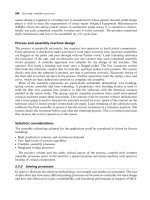
Tyre wear (Fig. 8.5) As the tyre depth is reduced,
the ability for the tread to drain off water being
swept in front of the tread is reduced. Therefore
with increased vehicle speed inadequate drainage
will reduce the tyre grip when braking (Fig. 8.5).
Road surface wetness (Fig. 8.6) The reduction in
tyre grip when braking from increased vehicle speed
drops off at a much greater rate as the rainfall
changes from light rain, producing a surface water
depth of 1 mm, to a heavy rainstorm flooding the
road to a water depth of about 2.5 mm (Fig. 8.6).
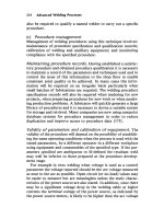
Road surface texture (Fig. 8.7) A new tyre braked
from various speeds will generate a higher peak
coefficient of adhesive friction with a smaller fall
off at the higher speeds on wet rough surfaces com-
pared to braking on wet smooth surfaces (Fig. 8.7).
The reduction in the coefficient of adhesive friction
when braking with worn tyres on both rough and
particularly smooth wet surfaces will be consider-
ably greater.
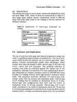
8.1.3 Road surface texture (Fig. 8.8)
A road surface finish may be classified by its texture
which may be broadly divided in macrotexture,
Fig. 8.5 Effect of speed on relative tyre grip with various
tread depth when braking on a wet road
Fig. 8.6 Effect of speed on relative tyre grip with various
road surface water depths
Fig. 8.7 Effect of speed on the coefficient of adhesive
friction with both wet rough and smooth surfaces
272
which represents the surface section peak to valley
ripple or roughness, and microtexture which is a
measure of the smoothness of the ripple contour
(Fig. 8.8). Further subdivisions may be made;
macrotexture may range from closed or fine going
onto open or coarse whereas microtexture may
range from smooth or polished extending to sharp
or harsh.
For good tyre grip under dry and wet conditions
the road must fulfil two requirements. Firstly, it
must have an open macrotexture to permit water
drainage. Secondly, it should have a microtexture
which is harsh; the asperities of the texture ripples
should consist of many sharp points that can pene-
trate any remaining film of water and so interact
with the tread elements. If these conditions are
fulfilled, a well designed tyre tread will provide
grip not only under dry conditions but also in wet
weather. A worn road surface may be caused by the
hard chippings becoming embedded below the soft
asphalt matrix or the microtexture of these chip-
pings may become polished. In the case of concrete
roads, the roughness of the brushed or mechanic-
ally ridged surface may become blunted and over
smooth. To obtain high frictional grip over a wide
speed range and during dry and wet conditions, it is
essential that the microtexture is harsh so that pure
rubber to road interaction takes place.
8.1.4 Braking characteristics on wet roads
(Fig. 8.9)
Maximum friction is developed between a rubber
tyre tread and the road surface under conditions of
slow movement or creep. A tyre's braking response
on a smooth wet road with the vehicle travelling at
a speed, say 100 km/h, will show the following
characteristics (Fig. 8.9).
When the brakes are in the first instance steadily
applied, the retardation rate measured as a fraction
of the gravitational acceleration (g m=s
2
)willrise
rapidly in a short time interval up to about 0.5 g.
This phase of braking is the normal mode of braking
when driving on motorways. In traffic, it enables the
Fig. 8.8 Terminology and road surface texture
Fig. 8.9 Possible retardation braking cycle on a wet road
273
driver to reduce the vehicle speed fairly rapidly with
good directional stability and no wheel lock taking
place. If an emergency braking application becomes
necessary, the driver can raise the foot brake effort
slightly to bring the vehicle retardation to its peak
value of just over 0.6 g, but then should immediately
release the brake, pause and repeat this on-off
sequence until the road situation is under control.
Failing to release the brake will lock the wheels so
that the tyre road grip changes from one of rolling to
sliding. As the wheels are prevented from rotating,
the braking grip generated between the contact
patches of the tyres drops drastically as shown in
the crash stop phase. If the wheels then remain
locked, the retardation rate will steady at a much
lower value of just over 0.2 g. The tyres will now
be in an entirely sliding mode, with no directional
stability and with a retardation at about one third
of the attainable peak value. With worn tyre treads
the braking characteristics of the tyres will be similar
but the braking retardation capacity is considerably
reduced.
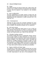
8.1.5 Rolling resistance (Figs 8.10 and 8.11)
When a loaded wheel and tyre is compelled to roll
in a given direction, the tyre carcass at the ground
interface will be deflected due to a combination of
the vertical load and the forward rolling effect on
the tyre carcass (Fig. 8.10). The vertical load tends
to flatten the tyre's circular profile at ground level,
whereas the forward rolling movement of the wheel
will compress and spread the leading contact edge
and wall in the region of the tread. At the same
time, the trailing edge will tend to reduce its contact
pressure and expand as it is progressively freed
from the ground reaction. The consequences of
the continuous distortion and recovery of the tyre
carcass at ground level means that energy is being
used in rolling the tyre over the ground and it is not
all returned as strain energy as the tyre takes up its
original shape. (Note that this has nothing to do
with a tractive force being applied to the wheel to
propel it forward.) Unfortunately when the carcass
is stressed, the strain produced is a function of the
stress. On releasing the stress, because the tyre
material is not perfectly elastic, the strain lags
behind so that the strain for a given value of stress
is greater when the stress is decreasing than when it
is increasing. Therefore, on removing the stress
completely, a residual strain remains. This is known
as hysteresis and it is the primary cause of the rolling
resistance of the tyre.
The secondary causes of rolling resistance are air
circulation inside the tyre, fan effect of the rotating
tyre by the air on the outside and the friction
between the tyre and road caused by tread slippage.
A typical analysis of tyre rolling resistance losses at
high speed can be taken as 90±95% due to internal
hysteresis, 2±10% due to friction between the tread
and ground, and 1.5±3.5% due to air resistance.
Rolling resistance is influenced by a number of
factors as follows:
a) cross-ply tyres have higher rolling resistance
than radial ply (Fig. 8.11),
b) the number of carcass plies and tread thickness
increase the rolling resistance due to increased
hysteresis,
c) natural rubber tyres tend to have lower rolling
resistance than those made from synthetic rubber,
Fig. 8.10 Illustration of side wall distortion at ground
level
Fig. 8.11 Effect of tyre construction on rolling resistance
274
d) hard smooth dry surfaces have lower rolling
resistances than rough or worn out surfaces,
e) the inflation pressure decreases the rolling resist-
ance on hard surfaces,
f) higher driving speed increases the rolling resist-
ance due to the increase in work being done in
deforming the tyre over a given time (Fig. 8.11),
g) increasing the wheel and tyre diameter reduces the
rolling resistance only slightly on hard surfaces but
it has a pronounced effect on soft ground,
h) increasing the tractive effort also raises the roll-
ing resistance due to the increased deformation
of the tyre carcass and the extra work needed to
be done.
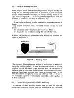
8.1.6 Tractive and braking effort (Figs 8.12,
8.13, 8.14, 8.15, 8.16 and 8.17)
A tractive effort at the tyre to ground interface is
produced when a driving torque is transmitted to
the wheel and tyre. The twisting of the tyre carcass
in the direction of the leading edge of the tread
contact patch is continuously opposed by the tyre
contact patch reaction on the ground. Before it
enters the contact patch region a portion of the
tread and casing will be deformed and compressed.
Hence the distance that the tyre tread travels when
subjected to a driving torque will be less than that
in free rolling (Fig. 8.12).
If a braking torque is now applied to the wheel
and tyre, the inertia on the vehicle will tend to pull
the wheel forward while the interaction between the
tyre contact patch and ground will oppose this
motion. Because of this action, the casing and tread
elements on the leading side of the tyre become
stretched just before they enter the contact patch
region in contrast with the compressive effect for
driving tyres (Fig. 8.13). As a result, when braking
torque is applied the distance the tyre moves will be
greater than when the tyre is subjected to free rolling
only. The loss or gain in the distance the tread
Fig. 8.12 Deformation of a tyre under the action of a driving torque
Fig. 8.13 Deformation of a tyre under the action of a braking torque
275
travels under tractive or braking conditions relative
to that in free rolling is known as deformation slip,
and it can be said that under steady state conditions
slip is a function of tractive or braking effort.
When a driving torque is applied to a wheel and
tyre there will be a steep initial rise in tractive force
matched proportionally with a degree of tyre slip,
due to the elastic deformation of the tyre tread. Even-
tually, when the tread elements have reached their
distortion limit, parts of the tread elements will begin
to slip so that a further rise in tractive force will
produce a much larger increase in tyre slip until the
peak or limiting tractive effort is developed. This
normally corresponds to on a hard road surface to
roughly 15±20% slip (Fig. 8.14). Beyond the peak
tractive effort a further increase in slip produces an
unstable condition with a considerable reduction in
tractive effort until pure wheel spin results (the tyre
just slides over the road surface). A tyre subjected to
a braking torque produces a very similar braking
effort response with respect to wheel slip, which is
now referred to as skid. It will be seen that the max-
imum braking effort developed is largely dependent
upon the nature of the road surface (Fig. 8.15) and
the normal wheel loads (Fig. 8.16), whereas wheel
speed has more influences on the unstable skid region
of a braking sequence (Fig. 8.17).
8.1.7 Tyre reaction due to concurrent
longitudinal and lateral forces (Fig. 8.18)
A loaded wheel and tyre rolling can generate only
a limited amount of tread to ground reaction to
resist the tyre slipping over the surface when the
tyre is subjected to longitudinal (tractive or braking)
forces and lateral (side) (cornering or crosswind)
forces simultaneously. Therefore the resultant com-
ponents of the longitudinal and lateral forces must
not exceed the tread to ground resultant reaction
force generated by all of the tread elements within
the contact area biting into the ground.
The relative relationship of the longitudinal and
lateral forces acting on the tyre can be shown by
Fig. 8.14 Effect of tyre slip on tractive effort
Fig. 8.15 Effect of ground surface on braking effort
Fig. 8.16 Effect of vertical load on braking effort
276
resolving both forces perpendicularly to each other
within the boundary of limiting reaction force
circle (Fig. 8.18(a and b)). This circle with its vector
forces shows that when longitudinal forces due to
traction or braking forces is large (Fig. 8.18(c and
d)), the tyre can only sustain a much smaller side
force. If the side force caused either by cornering or
a crosswind is large, the traction or braking effort
must be much reduced.
8.2 Tyre materials
8.2.1 The structure and properties of rubber
(Figs 8.19, 8.20 and 8.21)
The outside carcass and tread of a tyre is made from
a rubber compound that is a mix of several sub-
stances to produce a combination of properties
necessary for the tyre to function effectively. Most
metallic materials are derived from simple mole-
cules held together by electrostatic bonds which
sustain only a limited amount of stretch when sub-
jected to tension (Fig. 8.19). Because of this, the
material's elasticity may be restricted to something
like 2% of its original length. Rubber itself may be
either natural or synthetic in origin. In both cases
the material consists of many thousands of long
chain molecules all entangled together. When
stretched, the giant rubber molecules begin to
untangle themselves from their normal coiled state
and in the process of straightening out, provide a
considerable amount of extension which may be of
the order of 300% of the material's original length.
Thus it is not the electrostatic bonds being stretched
Fig. 8.17 Effect of vehicle speed on braking effort
Fig. 8.18(a±d) Limiting reaction force circle
277
but the uncoiling and aligning of the molecules in
the direction of the forces pulling the material apart
(Fig. 8.20). Consequently, when the tensile force is
removed the molecules revert to their free state
and thereby draw themselves into an entangled
network again. Hence it is not the bonds being
stretched but the uncoiling and aligning of the mole-
cules in the direction of the force pulling the material
apart.
Vulcanization To reduce the elasticity and to
increase the strength of the rubber, that is to restrict
the molecules sliding past each other when the sub-
stance is stretched, the rubber is mixed with a small
amount of sulphur and then heated, usually under
pressure. The chemical reaction produced is known
either as curing or more commonly as vulcanization
(named after Vulcan, the Roman god of fire). As a
result, the sulphur molecules form a network of
cross-links between some of the giant rubber mole-
cules (Fig. 8.21). The outcome of the cross-linking
between the entangled long chain molecules is that it
makes it more difficult for these molecules to slip
over each other so that the rubber becomes stronger
with a considerable reduction in flexibility.
Initiators and accelerator To start off and speed
up the vulcanization process, activators such as a
metallic zinc oxide are used to initiate the reaction
and an organic accelerator reduces the reaction
Fig. 8.19 Metal atomic lattice network
Fig. 8.20 Raw rubber network of long chain molecules
Fig. 8.21 Vulcanized rubber cross-linked network of long chain molecules
278
time and temperature needed for the sulphur to
produce a cross-link network.
Carbon black Vulcanized rubber does not have
sufficient abrasive resistance and therefore its rate
of wear as a tyre tread material would be very high.
To improve the rubber's resistance against wear
and tear about a quarter of a rubber compound
content is made up of a very fine carbon powder
known as carbon black. When it is heated to a
molten state the carbon combines chemically with
the rubber to produce a much harder and tougher
wear resistant material.
Oil extension To assist in producing an even
dispersion of the rubber compound ingredients
and to make processing of the tyre shape easier,
an emulsion of hydrocarbon oil is added (up to 8%)
to the rubber latex to dilute or extend the rubber.
This makes the rubber more plastic as opposed to
elastic with the result that it becomes tougher,
offers greater wear resistance and increases the
rubber's hysteresis characteristics thereby improv-
ing its wet grip properties.
Anti-oxidants and -ozonates Other ingredients such
as an anti-oxidant and anti-ozonate are added to
preserve the desirable properties of the rubber com-
pound over its service life. The addition of anti-
oxidants and -ozonates (1 or 2 parts per 100 parts
of rubber) prevents heat, light and particularly oxy-
gen ageing the rubber and making it hard and brittle.
8.2.2 Mechanical properties
To help the reader understand some of the terms
used to define the mechanical properties of rubber
the following brief definitions are given:
Material resilience This is the ability for a solid
substance to rebound or spring back to its original
dimensions after being distorted by a force. A
material which has a high resilience generally has
poor road grip as it tends to spring away from the
ground contact area as the wheel rolls forward.
Material plasticity This is the ability for a solid
material to deform without returning to its original
shape when the applied force is removed. A mater-
ial which has a large amount of plasticity promotes
good road grip as each layer of material tends to
cling to the road surface as the wheel rolls.
Material hysteresis This is the sluggish response of
a distorted material taking up its original form so
that some of the energy put into deforming the car-
cass, side walls and tread of a tyre at the contact
patch region will still not be released when the tyre
has completed one revolution and the next distortion
period commences. As the cycle of events continues,
more and more energy will be absorbed by the tyre,
causing its temperature to rise. If this heat is not
dissipated by the surrounding air, the inner tyre
fabric will eventually become fatigued and therefore
break away from the rubber encasing it, thus
destroying the tyre. For effective tyre grip a high
hysteresis material is necessary so that the distorted
rubber in contact with the ground does not immedi-
ately spring away from the surface but is inclined to
mould and cling to the contour of the road surface.
Material fatigue This is the ability of the tyre
structure to resist the effects of repeated flexing
without fracture, particularly with operating tem-
peratures which may reach something of the order
of 100
C for a heavy duty tyre although tempera-
tures of 80±85
C are more common.
8.2.3 Natural and synthetic rubbers
Synthetic materials which have been developed
as substitutes for natural rubber and have been
utilized for tyre construction are listed with natural
rubber as follows:
a) Natural rubber (NR)
b) Chloroprene (Neoprene) rubber (CR)
c) Styrene±butadiene rubber (SBR)
d) Polyisoprene rubber (IR)
e) Ethylene propylene rubber (EPR)
f) Polybutadiene rubber (BR)
g) Isobutene±isoprene (Butyl) rubber (IIR)
Natural rubber (NR) Natural rubber has good
wear resistance and excellent tear resistance. It
offers good road holding on dry roads but retains
only a moderately good grip on wet surfaces. One
further merit is its low heat build-up, but this is
contrasted by high gas permeability and its resist-
ance to ageing and ozone deterioration is only fair.
The side walls and treads have been made from
natural rubber but nowadays it is usually blended
with other synthetic rubbers to exploit their desir-
able properties and to minimize their shortcomings.
Chloroprene (Neoprene) rubber (CR) This syn-
thetic rubber is made from acetylene and hydro-
279
chloric acid. Wear and tear resistance for this rubber
compound, which was one of the earliest to com-
pete with natural rubber, is good with a reasonable
road surface grip. A major limitation is its inability
to bond with the carcass fabric so a natural rubber
film has to be interposed between the cords and the
Neoprene covering. Neoprene rubber has a moder-
ately low gas permeability and does not show signs
of weathering or ageing throughout a tyre's work-
ing life. When blended with natural rubber it is
particularly suitable for side wall covering.
Styrene±butadiene rubber (SBR) Compounds of
this material are made from styrene (a liquid) and
butadiene (a gas). It is probably the most widely
used synthetic rubber within the tyre industry.
Styrene±butadiene rubber (SBR) forms a very
strong bond to fabrics and it has a very good
resistance to wear, but suffers from poor tear resist-
ance compared to natural rubber. One outstanding
feature of this rubber is its high degree of energy
absorption or high hysteresis and low resilience. It
is these properties which give it exceptional grip,
especially on wet surfaces. Due to the high heat
build up, SBR is restricted to the tyre tread while
the side walls are normally made from low hyster-
esis compounds which provide greater rebound
response and run cooler. Blending SBR with NR
enables the best properties of both synthetic and
natural rubber to be utilized so that only one rub-
ber compound is necessary for some types of car
tyres. The high hysteresis obtained with SBR is
partially achieved by using an extra high styrene
content and by adding a large proportion of oil to
extend the compound, the effects being to increase
the rubber plastic properties and to lower its resili-
ence (i.e. reduce its rebound response).
Polyisoprene rubber (IR) This compound has very
similar characteristics to natural rubber but has
improved wear and particularly tear resistance with
a further advantage of an extremely low heat build up
with normal tyre flexing. These properties make this
material attractive when blended with natural rubber
and styrene±butadiene rubber to produce tyre treads
with very high abrasion resistance. For heavy duty
application such as track tyres where high tem-
peratures and driving on rough terrains are a pro-
blem, this material has proved to be successful.
Ethylene propylene rubber (EPR) The major
advantage of this rubber compound is its ability
to be mixed with large amounts of cheap carbon
black and oil without destroying its rubbery prop-
erties. It has excellent abrasive ageing and ozone
resistance with varying road holding qualities in
wet weather depending upon the compound com-
position. Skid resistance on ice has also been varied
from good to poor. A great disadvantage, however,
is that the rubber compound bonds poorly to cord
fabric. Generally, the higher the ethylene content
the higher the abrasive resistance, but at the
expense of a reduction in skid resistance on ice.
Rubber compounds containing EPR have not
proved to be successful up to the present time.
Polybutadiene rubber (BR) This rubbery material
has outstanding wear resistance properties and is
exceptionally stable with temperature changes. It
has a high resilience that is a low hysteresis level.
When blended with SBR in the correct proportions,
it reduces the wet road holding slightly and consider-
ably improves its ability to resist wear. Because of its
high resilience (large rebound response), if mixed in
large proportions, the road holding in wet weather
can be relatively poor. It is expensive to produce.
When it is used for tyres it is normally mixed with
SBR in the proportion of 15 to 50%.
Isobutene±isoprene (Butyl) rubber (IIR) Rubber of
this kind has exceptionally low permeability to gas.
In fact it retains air ten times longer than tubes
made from natural rubber, with the result that it
has been used extensively for tyre inner tubes and
for linings of tubeless tyres. Unfortunately it will
not blend with SBR and NR unless it is chlorinated,
but in this way it can be utilized as an inner tube
lining material for tubeless tyres. The resistance
to wear is good and it has a high hysteresis so
that it responds more like plastic than rubber to
distortion at ground level. Road grip is good for
both dry and wet conditions. When mixed with
carbon black its desirable properties are generally
improved. Due to its high hysteresis tyre treads
made from this material do not generate noise in
the form of squeal since it does not readily give out
energy to the surroundings.
8.2.4 Summary of the merits and limitations of
natural and synthetic rubber compounds
Some cross-ply tyres are made from one compound
from bead to bead, but the severity of the carcass
flexure with radial ply tyres encourages the
manufacturers of tyres to use different rubber
280
composition for various parts of the tyre structure
so that their properties match the duty require-
ments of each functional part of the tyre
(i.e. tread, side wall, inner lining, bead etc.).
Side walls are usually made from natural rubber
blended with polybutadiene rubber (BR) or styr-
ene±butadiene rubber (SBR) or to a lesser extent
Neoprene or Butyl rubber or even natural rubber
alone. The properties needed for side wall material
are a resistance against ozone and oxygen attack,
a high fatigue resistance to prevent flex cracking
and good compatibility with fabrics and other
rubber compounds when moulded together.
Tread wear fatigue life and road grip depends to
a great extent upon the surrounding temperatures,
weather conditions, be they dry, wet, snow or ice
bound, and the type of rubber compound being
used. A comparison will now be made with natural
rubber and possibly the most important synthetic
rubber, styrene±butadiene (SBR). At low tempera-
tures styrene±butadiene (SBR) tends to wear more
than natural rubber but at higher temperatures the
situation reverses and styrene±butadiene rubber
(SBR) shows less wear than natural rubber. As
the severity of the operating condition of the tyre
increases SBR tends to wear less relative to NR.
The fatigue life of all rubber compounds is reduced
as the degree of cyclic distortion increases. For
small tyre deflection SBR has a better fatigue life
but when deflections are large NR provides a
longer service life. Experience on ice and snow
shows that NR offers better skid resistance, but as
temperatures rise above freezing, SBR provides an
improved resistance to skidding. This cannot be
clearly defined since it depends to some extent on
the amount of oil extension (plasticizer) provided
in the blending in both NR and SBR compounds.
Oil extension when included in SBR and NR pro-
vides similarly improved skid resistance and in
both cases becomes inferior to compounds which
do not have oil extension.
Two examples of typical rubber compositions
suitable for tyre treads are:
a) High styrene butadiene rubber 31%
Oil extended butadiene rubber 31%
Carbon black 30%
Oil 6%
Sulphur 2%
b) Styrene butadiene rubber 45%
Natural rubber 15%
Carbon black 30%
Oil 8%
Sulphur 2%
8.3 Tyre tread design
8.3.1 Tyre construction
The construction of the tyre consists basically of
a carcass, inner beads, side walls, crown belt
(radials) and tread.
Carcass The carcass is made from layers of textile
core plies. Cross-ply tyres tend to still use nylon
whereas radial-ply tyres use either raylon or poly-
ester.
Beads The inside diameter of both tyre walls sup-
port the carcass and seat on the wheel rim. The
edges of the tyre contacting the wheel are known
as beads and moulded inside each bead is a
strengthening endless steel wire cord.
Side walls The outside of the tyre carcass, known
as the side walls, is covered with rubber compound.
Side walls need to be very flexible and capable of
protecting the carcass from external damage such
as cuts which can occur when the tyre is made to
climb up a kerb.
Bracing belt Between the carcass and tyre tread is
a crown reinforcement belt made from either syn-
thetic fabric cord such as raylon or for greater
strength steel cores. This circumferential endless
cord belt provides the rigidity to the tread rubber.
Tread The outside circumferential crown portion
of the tyre is known as the tread. It is made from
a hard wearing rubber compound whose function
is to grip the contour of the road.
8.3.2 Tyre tread considerations
The purpose of a pneumatic tyre is to support the
wheel load by a cushion of air trapped between the
well of the wheel rim and the toroid-shaped casing
known as the carcass. Wrapped around the outside
of the tyre carcass is a thick layer of rubber com-
pound known as the tread whose purpose is to pro-
tect the carcass from road damage due to tyre
impact with the irregular contour of the ground and
theabrasivewearwhichoccursasthetyrerollsalong
the road. While the wheel is rotating the tread pro-
vides driving, braking, cornering and steering grip
between the tyre and ground. Tyre grip must be
available under a variety of road conditions such as
smooth or rough hard roads, dry or wet surfaces,
muddly tracks, fresh snow or hard packed snow and
ice and sandy or soft soil terrain. Tread grip may be
defined as the ability of a rolling tyre to continuously
281
develop an interaction between the individual tread
elements and the ground so that any longitudinal
(driving) or lateral (side) forces imposed on the
wheelwillnotbeabletomakethetreadincontact
with the ground slide.
A tyre tread pattern has two main functions:
1 to provide a path for drainage of water which
might become trapped between the tyre contact
patch and the road,
2 to provide tread to ground bite when the wheel is
subjected to both longitudinal and lateral forces
under driving conditions.
8.3.3 Tread bite
Bite is obtained by selecting a pattern which divides
the tread into many separate elements and provid-
ing each element with a reasonably sharp well
defined edge. Thus as the wheel rotates these
tread edges engage with the ground to provide a
degree of mechanical tyre to ground interlock in
addition to the frictional forces generated when
transmitting tractive or braking forces.
The major features controlling the effectiveness
of the tread pattern in wet weather are:
1 drainage grooves or channels,
2 load carrying ribs,
3 load bearing blocks,
4 multiple microslits or sipes.
Tread drainage grooves (Fig. 8.22(a, b, c and d))
The removal of water films from the tyre to ground
interface is greatly facilitated by having a number of
circumferential grooves spaced out across the tread
width (Fig. 8.22(a)). These grooves enable the lead-
ing elements of the tread to push water through the
enclosed channels made by the road sealing the
underside of the grooves. Water therefore emerges
from the trailing side of the contact patch in the
form of jets. If these grooves are to be effective,
their total cross-sectional area should be adequate
to channel all the water immediately ahead of the
leading edge of the contact patch away. If it cannot
cope the water will become trapped between the
tread ribs or blocks so that these elements lift and
become separated from the ground, thus reducing
the effective area of the contact patch and the tyre's
ability to grip the ground.
To speed up the water removal process under the
contact patch, lateral grooves may be used to join
together the individual circumferential grooves and
to provide a direct side exit for the outer circumfer-
ential grooves. Normally many grooves are pre-
ferred to a few large ones as this provides a better
drainage distribution across the tread.
Tread ribs (Fig. 8.22(a and b)) Circumferential
ribs not only provide a supportive wearing surface
for the tyre but also become the walls for the drainage
grooves (Fig. 8.22(a and b)). Lateral (transverse)
ribs or bars provide the optimum bite for tractive
and braking forces but circumferential ribs are most
effective in controlling cornering and steering stabi-
lity. To satisfy both longitudinal and lateral direc-
tional requirements which may be acting concurrently
on the tyre, ribs may be arranged diagonally or in
the form of zig-zag circumferential ribs to improve
the wiping effect across the tread surface under wet
conditions. It is generally better to break the tread
pattern into many narrow ribs than a few wide ones,
as this prevents the formation of hydrodynamic
water wedges which may otherwise tend to develop
Fig. 8.22(a±d) Basic tyre tread patterns
282
with the consequent separation of the tread elements
from the road.
Tread blocks (Figs 8.22(c and d) and 8.23(a and b))
If longitudinal circumferential grooves in the mid-
dle of the tread are complemented by lateral (trans-
verse) grooves channelled to the tread shoulders,
then with some tread designs the drainage of water
can be more effective at speed. The consequences of
both longitudinal and lateral drainage channels is
that the grooves encircle portions of the tread so
that they become isolated island blocks (Fig. 8.22
(c and d)). These blocks can be put to good use as
they provide a sharp wiping and biting edge where
the interface of the tread and ground meet. To
improve their biting effectiveness for tractive and
braking forces as well as steering and cornering
forces, these forces may be resolved into diagonal
resultants so that the blocks are sometimes
arranged in an oblique formation. A limitation to
the block pattern concept is caused by inadequate
support around the blocks so that under severe
operating conditions, the bulky rubber blocks
tend to bend and distort. This can be partially
overcome by incorporating miniature buttresses
between the drainage grooves which lean between
blocks so that adjacent blocks support each other.
At the same time, drainage channels which burrow
below the high mounted buttresses are prevented
from closing. Tread blocks in the form of bars, if
arranged in a herringbone fashion, have proved to
be effective on rugged ground. Square or rhombus-
shaped blocks provide a tank track unrolling
action greatly reducing movement in the tread con-
tact area. This pattern helps to avoid the break-up
on the top layer of sand or soil and thus prevents
the tyre from digging into the ground. Because of
the inherent tendency of the individual blocks to
bend somewhat when they are subjected to ground
reaction forces, they suffer from toe to heel rolling
action which causes blunting of the leading edge
and trailing edge feathering. Generally tyres which
develop this type of wear provide a very good water
sweeping action when new, which permits the tread
elements to bite effectively into the ground, but
after the tyre has been on the road for a while, the
blunted leading edge allows water to enter under-
neath the tread elements. Consequently the slight-
est amount of water interaction between the block
elements and ground reduces the ability for the
tread to bite and in the extreme cases under locked
wheel braking conditions a hydrodynamic water
wedge action may result, causing a mild form of
aquaplaning to take place.
Fortreadblockelementstomaintaintheirwiping
action on wet surfaces, wear should be from toe to
heel (Fig. 8.23(a)). If, however, wear occurs in the
reverse order, that is from heel to toe (Fig. 8.23(b)),
the effectiveness of the tread pattern will be severely
reduced since the tread blocks then become the plat-
form for a hydrodynamic water wedge which at
speed tries to lift the tread blocks off the ground.
Tread slits or sipes (Figs 8.22(a, b, c and d) and
8.24(a, b and c)) Microslits, or sipes as they are
commonly called, are incisions made at the surface
of the tyre tread, going down to the full depth of
the tread grooves. They resemble a knife cut, except
that instead of being straight they are mostly of
a zig-zag nature (Fig. 8.22(a, b, c and d)). Normally
these sipes terminate within the tread elements, but
sometimes one end is permitted to intersect the side
wall of a drainage groove. In some tread patterns
the sipes are all set at a similar angle to each other,
the zig-zag shape providing a large number of edges
which point in various directions. Other designs
have sets of sipes formed at different angles to
each other so that these sipes are effective which-
ever way the wheel points and whatever the direc-
tion the ground reaction forces operate.
Sipes or slits in their free state are almost closed,
but as they move into the contact patch zone the
ribs or blocks distort and open up (Fig. 8.24(a)).
Because of this, the sipe lips scoop up small quan-
tities of water which still exist underneath the tread.
This wiping action enables some biting edge reac-
tion with the ground. Generally, the smaller the
sipes are and more numerous they are the greater
will be their effective contribution to road grip. The
Fig. 8.23(a and b) Effect of irregular tread block wear
283
normal spacing of sipes (microslits) on a tyre tread
makes them ineffective on a pebbled road surface
because there will be several pebbles between the
pitch of the sipes (Fig. 8.24(b)), and water will lie
between these rounded stones, therefore only a few
of the stones will be subjected to the wiping edge
action of the opened lips. An alternative method to
improve the wiping process would be to have many
more wiping slits (Fig. 8.24(c)), but this is very
difficult to implement with the present manufactur-
ing techniques. The advantages to be gained by
multislits are greatest under conditions of low fric-
tion associated with thin water films on smooth
and polished road surfaces. This is because the
road surface asperities are not large and sharp
enough to penetrate the thin water film trapped
under plain ribs and blocks.
Selection of tread patterns (Fig. 8.25(a±1))
Normal car tyres (Fig. 8.25(a, b and c)) General
duty car tyres which are capable of operating effect-
ively at all speeds tend to have tread blocks situ-
ated in an oblique fashion with a network of
surrounding drainage grooves which provide both
circumferential and lateral water release.
Winter car tyres (Fig. 8.25(d, e and f)) Winter car
tyres are normally very similar to the general duty
car tyre but the tread grooves are usually wider to
permit easier water dispersion and to provide better
exposure of the tread blocks to snow and soft ice
without sacrificing too much tread as this would
severely reduce the tyre's life.
Truck tyres (Fig. 8.25(g and h)) Truck tyres
designed for steered axles usually have circumferen-
tial zig-zag ribs and grooves since they provide very
good lateral reaction when being steered on curved
tracks. Drive axle tyres, on the other hand, are
designed with tread blocks with adequate grooving
so that optimum traction grip is obtained under
both dry and wet conditions. Some of these tyres
also have provision for metal studs to be inserted for
severe winter hard packed snow and ice conditions.
Fig. 8.24(a±c) Effectiveness of microslits on wet road surfaces
284
Fig. 8.25(a±l) Survey of tyre tread patterns
285
Off/on road vehicles (Fig. 8.25(i)) Off/on road
vehicle tyres usually have a much simpler bold
block tread with a relatively large surrounding
groove. This enables each individual block to react
independently with the ground and in this manner
bite and exert traction on soil which may be hard on
the surface but soft underneath without break-up of
the top layer, thus preventing the tyre digging in.
The tread pattern blocks are also designed to be
small enough to operate on hard surfaced roads at
moderate speeds without excessive ride harshness.
Truck and tractor off road and cross-country tyres
(Fig. 8.25(j, k and l)) Truck or tractor tyres
designed for building sites or quarries generally
have slightly curved rectangular blocks separated
with wide grooves to provide a strong flexible cas-
ing and at the same time present a deliberately
penetrating grip. Cross-country tyres which tend
to operate on soft soil tend to prefer diagonal
bars either merging into a common central rib or
arranged with separate overlapping diagonal bars,
as this configuration tends to provide exceptionally
good traction on muddy soil, snow and soft ice.
8.3.4 The three zone concept of tyre to ground
contact on a wet surface (Fig. 8.26)
The interaction of a tyre with the ground when
rolling on a wet surface may be considered in
three phases (Fig. 8.26):
Leading zone of unbroken water film (1) The lead-
ing zone of the tread contacts the stagnant water
film covering the road surface and displaces the
majority of the water into the grooves between
the ribs and blocks of the tread pattern.
Intermediate region of partial breakdown of water
film (2) The middle zone of the tread traps and
reduces the thickness of the remaining water
Fig. 8.25 contd
Fig. 8.26 Tyre to ground zones of interaction
286
between the faces of the ribs or blocks and ground
so that some of the road surface asperities now
penetrate through the film of water and may actu-
ally touch the tread. It is this region which is respon-
sible for the final removal of water and is greatly
assisted by multiple sipes and grooved drainage
channels. If the ribs and blocks are insufficiently
relieved with sipes and grooves it is possible that
under certain conditions aquaplaning may occur in
this region.
The effectiveness of this phase is determined to
some extent by the texture of the road surface, as
this considerably influences the dryness and
potency of the third road grip phase.
Trailing zone of dry tyre to road contact (3)The
water film has more or less been completely
squeezed out at the beginning of this region so that
the faces of the ribs and blocks bearing down on the
ground are able to generate the bite which produces
the tractive, braking and cornering reaction forces.
8.3.5 Aquaplaning (hydroplaning) (Fig. 8.27)
The performance of a tyre rolling on wet or semi-
flooded surface will depend to some degree upon
the tyre profile tread pattern and wear. If a smooth
tread is braked over a very wet surface, the forward
rotation of the tyre will drag in the water immedi-
ately in front between the tread face and ground
and squeeze it so that a hydrodynamic pressure is
created. This hydrodynamic pressure acts between
the tyre and ground, its magnitude being propor-
tional to the square of the wheel speed. With the
wheel in motion, the water will form a converging
wedge between the tread face and ground and so
exert an upthrust on the underside of the tread. As
a result of the pressure generated, the tyre tread will
tend to separate itself from the ground. This con-
dition is known as aquaplaning or hydroplaning. If
the wheel speed is low only the front region of the
tread rides on the wedge of water, but if the speed is
rising the water wedge will progressively extend
backward well into the contact patch area (Fig.
8.27). Eventually the upthrust created by the pro-
duct of the hydrodynamic pressure and contact area
equals the vertical wheel load. At this point the tyre
is completely supported by a cushion of water and
therefore provides no traction or directional control.
If the tread has circumferential (longitudinal) and
transverse (lateral) grooves of adequate depth then
the water will drain through these passages at
ground level so that aquaplaning is minimized even
at high speeds. As the tyre tread wears the critical
speed at which aquaplaning occurs becomes much
lower. On very wet roads a bald tyre is certain to be
subjected to aquaplaning at speeds above 60 km/h
and therefore the vehicle when driven has no
directional stability. Low aspect ratio tyres may
find it difficult to channel the water away from
the centre of the tread at a sufficiently high
Fig. 8.27 Tyre aquaplaning
287
rate and therefore must rely more on the circumfer-
ential grooves than on transverse grooving.
8.3.6 Tyre profile and aspect ratio (Fig. 8.28)
The profile of a tyre carcass considerably influences
its rolling and handling behaviour. Because of the
importance of the tyre's cross-sectional configura-
tion in predicting its suitability and performance for
various applications, the aspect ratio was intro-
duced. This constant for a particular tyre may be
defined as the ratio of the tyre cross-sectional height
(the distance between the tip of the tread to the bead
seat) to that of the section width (the outermost
distance between the tyre walls) (Fig. 8.28).
i:e: Aspect ratio
Section height
Section width
 100
A tyre with a large aspect ratio is referred to as
a high aspect ratio profile tyre and a tyre with a small
aspect is known as a low aspect ratio profile. Until
about 1934 aspect ratios of 100% were used, but
with the better understanding of pneumatic tyre
properties and improvement in tyre construction
lower aspect ratio tyres became available. The avail-
ability of lower aspect ratio tyres over the years was
as follows; 1950s±95%, 1962±88% (this was the
standard for many years), 1965±80% and about
1968±70%. Since then for special applications even
lower aspect ratios of 65%,60%,55% and even 50%
have become available.
Lowering the aspect ratio has the following
effects:
1 The tyre side wall height is reduced which
increases the vertical and lateral stiffness of the
tyre.
2 A shorter and wider contact patch is established.
The overall effect is to raise the load carrying
capacity of the tyre.
3 The wider contact patch enables larger cornering
forces to be generated so that vehicles are able to
travel faster on bends.
4 The shorter and wider contact patch decreases
the pneumatic trail which correspondingly
reduces and makes more consistent the self-
aligning torque.
5 The shorter and broader contact patch will,
under certain driving conditions, reduce the slip
angles generated by the tyre when subjected to
side forces. Accordingly this reduces the tread
distortion and as a result scuffing and wear will
decrease.
6 With an increase in vertical stiffness and a reduc-
tion in tyre deflection with lower aspect ratio
tyres, less energy will be dissipated by the tyre
casing so that rolling resistance will be reduced.
This also results in the tyre being able to run
continuously at high speeds at lower tempera-
tures which tends to prolong the tyre's life.
7 The increased lateral stiffness of a low profile tyre
will increase the sensitivity to camber variations
and quicken the response to steering changes.
8 Wider tyre contact patches make it more difficult
for water drainage at speed particularly in the
mid tread region. Hence the tread pattern design
with low profile tyres becomes more critical on
wet roads, if their holding is to match that of
higher aspect ratio tyres.
9 The increased vertical stiffness of the tyre
reduces static deflection of the tyre under load,
so that more road vibrations are transmitted
through the tyre. This makes it a harsher ride
so that ride comfort is reduced unless the suspen-
sion design has been able to provide more isola-
tion for the body.
8.4 Cornering properties of tyres
8.4.1 Static load and standard wheel height
(Figs 8.29 and 8.30)
A vertical load acting on a wheel will radially
distort the tyre casing from a circular profile to
a short flat one in the region of the tread to ground
interface (Fig. 8.29). The area of the tyre contact
with the ground is known as the tyre contact patch
area; its plan view shape is roughly elliptical. The
consequence of this tyre deflection is to reduce the
Fig. 8.28 Tyre profiles with different aspect ratios
288
standard height of the wheel, that is the distance
between the wheel axis and the ground. Generally
tyre deflection will be proportional to the radial
load imposed on the wheel; increasing the tyre
inflation pressure reduces the tyre deflection for
a given vertical load (Fig. 8.30). Note that there is
an initial deflection (Fig. 8.30) due to the weight of
the wheel and tyre alone. The steepness of the load
deflection curve is useful in estimating the static
stiffness of the tyres which can be interpreted as
a measure of its vibration and ride qualities.
8.4.2 Tyre contact patch (Figs 8.29 and 8.31)
The downward radial load imposed on a road
wheel causes the circular profile of the tyre in con-
tact with the ground to flatten and spread towards
the front and rear of its natural rolling plane. When
the wheel is stationary, the interface area between
the tyre and ground known as the contact patch
will take up an elliptical shape (Fig. 8.29), but if the
wheel is now subjected to a side thrust the grip
between the tread and ground will distort the
patch into a semibanana configuration (Fig. 8.31
(a)). It is the ability of the tyre contact patch casing,
and elements of the tread to comply and change
shape due to the imposed reaction forces, which
gives tyres their steering properties. Generally,
radial ply tyres form longer and broader contact
patches than their counterpart cross-ply tyres,
hence their superior road holding.
8.4.3 Cornering force (Fig. 8.31(a and b))
Tyres are subjected not only to vertical forces but
also to side (lateral) forces when the wheels are in
motion due to road camber, side winds, weight
transfer and centrifugal force caused by travelling
round bends and steering the vehicle on turns. When
a side force, sometimes referred to as lateral force, is
imposed on a road wheel and tyre, a reaction
between the tyre tread contact patch and road sur-
face will oppose any sideway motion. This resisting
force generated at the tyre to road interface is
known as the cornering force (Fig. 8.31(a and b)),
its magnitude being equal to the lateral force
but it acts in the opposite sense. The amount of
Fig. 8.29 Illustration of static tyre deflection
Fig. 8.30 Effect of tyre vertical load on static deflection
289
cornering force developed increases roughly in pro-
portion with the rise in lateral force until the grip
between the tyre tread and ground diminishes.
Beyond this point the cornering force cannot
match further increases in lateral force with the
result that tyre breakaway is likely to occur. Note
that the greater the cornering force generated
between tyre and ground, the greater the tyre's grip
on the road.
The influencing factors which determine the
amount of cornering force developed between the
tyre and road are as follows:
Slip angle Initially the cornering force increases
linearly with increased slip angle, but beyond about
four degrees slip angle the rise in cornering force is
non-linear and increases at a much reduced rate (Fig.
8.32), depending to a greater extent on tyre design.
Vertical tyre load As the vertical or radial load on
the tyre is increased for a given slip angle, the
cornering force rises very modestly for small slip
angles but at a far greater rate with larger slip angles
(Fig. 8.33).
Tyre inflation pressure Raising the tyre inflation
pressure linearly increases the cornering force for a
given slip angle (Fig. 8.34). These graphs also show
that increasing the tyre slip angle considerably
raises the cornering forces generated.
8.4.4 Slip angle (Fig. 8.31(a))
Any lateral force applied to a road wheel will tend to
push the supple tyre walls sideways, but the oppos-
ing tyre to ground reaction causes the tyre contact
patch to take up a curved distorted shape. As a
result, the rigid wheel will point and roll in the
direction it is steered, whereas the tyre region in
contact with the ground will follow the track con-
tinuously laid down by the deformed tread path of
the contact patch (Fig. 8.31(a)). The angle made
between the direction of the wheel plane and that
which it travels is known as the slip angle. Provided
the slip angle is small, the compliance of the tyre
construction will allow each element of tread to
remain in contact with the ground without slippage.
8.4.5 Cornering stiffness (cornering power)
(Fig. 8.32)
When a vehicle travels on a curved path, the centri-
fugal force (lateral force) tends to push sideways
each wheel against the opposing tyre contact patch
to ground reaction. As a result, the tyre casing and
tread in the region of the contact patch very slightly
deform into a semicircle so that the path followed by
the tyre at ground level will not be quite the same as
the direction of the wheel points. The resistance
offered by the tyre crown or belted tread region by
the casing preventing it from deforming and gener-
ating a slip angle is a measure of the tyre's corner-
ing power. The cornering power, nowadays more
Fig. 8.31 Tyre tread contact patch distortion when subjected to a side force
290
usually termed cornering stiffness, may be defined as
the cornering force required to be developed for
every degree of slip angle generated.
i.e.
Cornering stiffness
Cornering force
Slip angle
(kN=deg)
In other words, the cornering stiffness of a tyre is
the steepness of the cornering force to slip angle
curve normally along its linear region (Fig. 8.32).
The larger the cornering force needed to be gener-
ated for one degree of slip angle the greater the
cornering stiffness of the tyre will be and the
smaller the steering angle correction will be to sus-
tain the intended path the vehicle is to follow. Note
that the supple flexing of a radial ply side wall
should not be confused with the actual stiffness of
the tread portion of the tyre casing.
8.4.6 Centre of pressure (Fig. 8.35)
When a wheel standing stationary is loaded, the
contact patch will be distributed about the geo-
metric centre of the tyre at ground level, but as the
wheel rolls forward the casing supporting the tread
is deformed and pushed slightly to the rear (Fig.
8.35). Thus in effect the majority of the cornering
force generated between the ground and each
element of tread moves from the static centre of
pressure to some dynamic centre of pressure behind
the vertical centre of the tyre, the amount of
displacement corresponding to the wheel construc-
tion, load, speed and traction. The larger area of
tread to ground reaction will be concentrated behind
the static centre of the wheel and the actual distribu-
tion of cornering force from front to rear of the
contact patch is shown by the shaded area between
the centre line of the tyre and the cornering force
plotted line. The total cornering force is therefore
roughly proportional to this shaded area and its
resultant dynamic position is known as the centre
of pressure (Fig. 8.35).
8.4.7 Pneumatic trail (Fig. 8.35)
The cornering force generated at any one time will
be approximately proportional to the shaded area
between the tyre centre line and the cornering force
plotted line so that the resultant cornering force
(centre of pressure) will act behind the static centre
of contact. The distance between the static and
dynamic centres of pressure is known as the pneu-
matic trail (Fig. 8.35), its magnitude being depen-
dent upon the degree of creep between tyre and
ground, the vertical wheel load, inflation pressure,
speed and tyre constriction. Generally with the
longer contact patch, radial ply tyres have a greater
pneumatic trail than those of the cross-ply
construction.
8.4.8 Self-aligning torque (Fig. 8.35)
When a moving vehicle has its steering wheels
turned to negotiate a bend in the road, the lateral
(side) force generates an equal and opposite
Fig. 8.32 Effect of slip angle on cornering force
Fig. 8.33 Effect of tyre vertical load on cornering force
291