Advanced Vehicle Technology Episode 2 Part 10 pdf
Bạn đang xem bản rút gọn của tài liệu. Xem và tải ngay bản đầy đủ của tài liệu tại đây (286.12 KB, 20 trang )
times tending to align themselves with the wheels
rolling when the steering has been turned to one
lock. As a result the trailing or leading offset x
produces a self-righting effect to the steered wheels.
The greater the angle the wheels have been steered,
the larger the pivot centre to contact patch centre
offset x and the greater the castor self-centring
action will be. The self-righting action which
tends to straighten out the steering after it has
been turned from the straight position, increases
with both wheel traction and vehicle speed.
10.1.5 Swivel joint positive and negative offset
(Figs 10.10±10.15)
When one of the front wheels slips during a brake
application, the inertia of the moving mass will
tend to swing the vehicle about the effective wheel
which is bringing about the retardation because
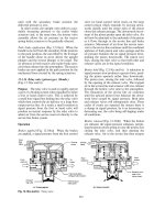
Fig. 10.8 Castor angle steering geometry
(a) Rear wheel drive castor
angle self-righting torque effect
(b) Front wheel drive castor
angle self-righting torque effect
Castor angle
self-righting
torque (M)
Castor angle
self-righting
torque (M)
F
R
F
R
F
D
Fig. 10.9 (a and b) Illustration of steered wheel castor self-straightening tendency
372
there is very little opposing resistance from the
wheel on the opposite side (Fig. 10.12).
If the offset of the swivel ball joints is on the
inside of the tyre contact patch the swivel inclin-
ation is known as positive offset (Fig. 10.10). When
the wheels are braked the positive offset distance
and the inertia force of the vehicle produce a turn-
ing movement which makes the wheels pivot about
the contact patch centre in an outward direction at
the front (Fig. 10.10). If the off side (right) wheel
moves onto a slippery patch, the vehicle will not
only veer to the left, due to the retarding effect of
the good braked wheel preventing the vehicle mov-
ing forward, but the near side (left) wheel will also
turn and steer to the left (Fig. 10.13). Therefore the
positive offset compounds the natural tendency for
the vehicle to swerve towards the left if the right
hand wheel skids instead of continuing on a stable
straight ahead path.
Arranging for the swivel ball joint inclination
centre line to intersect the ground on the outside of
the contact patch centre produces what is known as
negative offset (Fig. 10.11). With negative offset the
Fig. 10.10 Swivel pin inclination positive offset
Fig. 10.11 Swivel pin inclination negative offset
Fig. 10.12 Directional stability when one wheel skids
whilst being braked
373
momentum of the vehicle will produce a turning
moment that makes the wheels swivel inwards at
the front about the contact patch centre (Fig. 10.11)
because the swivel ball joints and stub axle assembly
are being pulled forwards and around the patch
centre caused by the negative offset distance. The
consequence of negative offset is that the effective
braked wheel twists in the opposite direction to that
to which the vehicle tends to veer (Fig. 10.14) and so
counteracts the swerving tendency, enabling the
vehicle to remain in a stable straight ahead direction.
In both positive and negative offset layouts, the
skidding wheel turns in the same direction as the
initial swerving tendency, but since it is not con-
tributing greatly to the tyre to ground grip, its
influence on directional stability is small.
The effect of negative offset is ideal for a split
line braking system where if one brake line should
fail, the front brake on the opposite side will still
operate as normal (Fig. 10.14). The tendency for
the car to veer to the side of the braked wheel is
partially corrected by the wheel being turned due to
the negative offset in the opposite direction
(inwards), away from the direction in which the
car wants to swerve.
When cornering, the sideways distortion of the
tyre walls will misalign the wheel centre to that of
the tread centre so that the swivel ball joint inclin-
ation offset will alter. The outer front wheel
which supports the increase in weight due to
body roll reduces positive offset (Fig. 10.15(a)),
while negative offset becomes larger (Fig.
10.15(b)) and therefore makes it easier for the
car to be steered when negotiating a bend in the
road.
10.1.6 MacPherson strut friction and spring
offset (Figs 10.16 and 10.17)
The MacPherson strut suffers from stickiness
in the sliding motion of the strut, particularly
under light load with an extended strut since
the cylinder rod bearing and the damper piston
will be closer together. Because the alignment
of the strut depends upon these two sliding
members, extending and reducing their dis-
tance will increase the side loading under these
conditions.
The problem of reducing friction between the
inner and outer sliding members is largely over-
come in two ways:
Fig. 10.13 Directional stability with positive offset when
one wheel skids whilst being braked
Fig. 10.14 Directional stability with negative offset when
one wheel skids whilst being braked
374
(a) By reducing the friction, particularly with any
initial movement, using a condition which is
known as stiction. This is achieved by facing
the bearing surfaces with impregnated poly-
tetra-fluorethytene (PTFE) which gives the
rubbing pairs an exceptionally low coefficient
of friction.
(b) By eliminating the bending moment on the
strut under normal straight ahead driving
although there will be a bending moment
under cornering conditions.
The tendency for the strut to bend arises because
the wheel is offset sideways from the strut, causing
the stub axle to act as a cantilever from the base of
the strut to the wheel it supports, with the result the
strut bends in a curve when extended or under
heavy loads (Fig. 10.16).
A simple solution which is commonly applied to
reduce the bending moment on the strut is to angle
the axis of the coil spring relative to the swivel joint
axis causing the spring to apply a bending moment
in the opposite sense to the vehicle load bending
moment (Fig. 10.17). Under normal conditions this
coil spring axis tilt is sufficient to neutralize the
bending moment caused by the inclined strut and
the stub axle offset, but the forces involved while
cornering produce much larger bending moments
which are absorbed by the rigidity of the strut alone.
10.2 Suspension roll centres
Roll centres (Fig. 10.29) The roll centre of a sus-
pension system refers to that centre relative to the
ground about which the body will instantaneously
Fig. 10.15 (a and b) Swivel pin inclination offset change
when cornering
Fig. 10.16 Concentric coil spring and swivel pin axes
permit bending moment reaction
Fig. 10.17 Coil spring to swivel pin axis offset
counteracts bending moment
375
rotate. The actual position of the roll centre varies
with the geometry of the suspension and the angle
of roll.
Roll axis (Fig. 10.29) The roll axis is the line join-
ing the roll centres of the front and the rear suspen-
sion. Roll centre height for the front and rear
suspension will be quite different; usually the front
suspension has a lower roll centre than that at the
rear, causing the roll axis to slope down towards the
front of the vehicle. The factors which determine
the inclination of the roll axis will depend mainly
on the centre of gravity height and weight distribu-
tion between front and rear axles of the vehicle.
10.2.1 Determination of roll centre height
(Fig. 10.18)
The determination of the roll centre height can be
best explained using the three instantaneous centre
method applied to the swing axle suspension, which
is the basic design used for the development of
almost any suspension geometry (Fig. 10.18).
A vehicle's suspension system involves three
principal items; the suspended body B, the support-
ing wheels W and the ground G which provides the
reaction to the downward load of the vehicle.
If a body which is suspended between two pairs
of wheels is to be capable of rolling relative to the
ground, then there must be three instantaneous
centres as follows:
1I
BG
the instantaneous centre of the body relative
to the ground which is more commonly known
as the body roll centre,
2I
WB
the instantaneous centre of the wheel relative
to the body which is the swing arm point of pivot,
3I
WG
the instantaneous centre of the wheel rela-
tive to the ground which is the contact centre
between the tyre and ground. It therefore forms
a pivot permitting the top of the wheel to tilt
laterally inwards or outwards.
10.2.2 Short swing arm suspension
(Fig. 10.18)
When cornering, an overturning moment is gener-
ated which makes the body roll outwards from the
centre of turn. The immediate response is that the
inner and outer swing arm rise and dip respectively
at their pivoted ends so that the inner and outer
wheels are compelled to tilt on their instantaneous
tyre to ground centres, I
WG
1
and I
WG
2
, in the oppos-
ite direction to the body roll.
For effective body roll to take place there
must be two movements within the suspension
geometry:
1 The swing arm pivot instantaneous centres I
WB
1
and I
WB
2
rotate about their instantaneous centres
I
WG
1
and I
WG
2
in proportion to the amount of
body roll.
2 The swing arm pivot instantaneous centres I
WB
1
and I
WB
2
move on a circular path which has a
centre derived by the intersecting projection lines
drawn through the tyre to ground instantaneous
centres I
WG
1
and I
WG
2
.
The tilting, and therefore rotation, of both
swing arms about the tyre to ground instant-
aneous centres I
WG
1
and I
WG
2
will thus produce
an arc which is tangential to the circle on which
the swing arm pivot instantaneous centres I
WB
1
and I
WB
2
touch. Therefore, the intersecting point
I
BG
, where the projection lines which are drawn
through the wheel to ground contact points and
the swing arm pivots meet, is the instantaneous
centre of rotation for the body relative to the
ground. This point is usually referred to as the
body roll centre.
Thus the body roll centre may be found by draw-
ing a straight line between the tyre contact centre
and swing arm pivot centre of each half suspension
and projecting these lines until they intersect some-
where near the middle of the vehicle. The point of
intersection becomes the body roll centre.
The roll centre height may be derived for a short
swing arm suspension by consideration of similar
triangles:
h
t=2
r
l
where h = Roll centre height
t = Track width
r = Wheel radius
l = Swing arm length
Hence h
tr
2l
Fig. 10.18 Short swing axle
376
10.2.3 Long swing arm suspension (Fig. 10.19)
The long swing arm suspension is very similar to
the short swing arm arrangement previously
described, but the arms extend to the opposite
side of the body relative to its wheel it supports
and therefore both arms overlap with each other
(Fig. 10.19).
The roll centre is determined by joining the tyre
contact centre and the swing arm pivot centre by a
straight line for each half suspension. The point
where these lines meet is the body roll centre and
its distance above or below the ground is known as
the roll centre height. Because the long swing arm
suspension has a much longer arm than used on the
short swing arm layout, the slope of the lines join-
ing the tyre contact centre and swing arm pivot is
not so steep. Therefore the crossover point which
determines the body roll centre height is lower for
the long swing arm than for the short swing arm
suspension.
The inherent disadvantage of the short swing
arm suspension is that there is too much camber
change with body roll and there is a tendency for
the axle arms to jack the body up when cornering.
Whereas the long swing arm suspension would
meet most of the requirements for a good quality
ride, it is impractical for a front suspension layout
as it would not permit the engine to be situated
relatively low between the two front wheels.
10.2.4 Transverse double wishbone suspension
(Figs 10.20, 10.21 and 10.22)
If lines are drawn through the upper and lower
wishbone arms and extended until they meet either
inwards (Fig. 10.20) or outwards (Fig. 10.21), their
intersection point becomes a virtual instantaneous
centre for an imaginary (virtual) triangular swing
arm suspension. The arc scribed by the wishbone
arms pivoting relative to the body is almost iden-
tical to that of the imaginary or virtual arm which
swings about the instantaneous virtual centres I
BW
1
and I
BW
2
for small movements of the suspension.
Therefore, the body roll centre for a transverse
double wishbone suspension can be derived simi-
larly to a long swing arm suspension.
For inwardly converging transverse upper and
lower wishbone arm suspension (Fig. 10.20) the
body roll centre can be derived in two stages.
Firstly, extend straight lines through the wishbone
arms until they meet somewhere on the opposite
side of the body at their virtual instantaneous
centres I
WB
1
and I
WB
2
. Secondly, draw straight lines
between the tyre contact centres I
WG
1
and I
WG
2
and
the virtual centres I
BW
1
and I
BW
2
for each half
suspension. The point where these inclined lines
intersect is therefore the body roll centre I
BG
.
For outward converging transverse upper and
lower wishbone arm suspension (Fig. 10.21) the
body roll centre is found again by drawing two
Fig. 10.19 Long swing axle
Fig. 10.20 Inward converging transverse double
wishbone
Fig. 10.21 Outward converging transverse double
wishbone
Fig. 10.22 Parallel transverse double wishbone
377
sets of lines. Firstly project straight lines through
the wishbone arms for each side of the vehicle until
they meet somewhere on the outside of each wheel
at their virtual instantaneous centres I
WB
1
and I
WB
2
.
Next draw straight lines between the tyre contact
centres I
WG
1
and I
WG
2
and the virtual centres I
WB
1
and I
WB
2
for each half suspension, and at the same
time extend these lines until they intersect near the
middle of the vehicle. This point therefore becomes
the body roll centre I
BG
. It can be seen that inclin-
ing the wishbone arms so that they either converge
inward or outward produces a corresponding high
and low roll centre height.
With parallel transverse upper and lower wish-
bone arms suspension (Fig. 10.22) lines drawn
through the double wishbone arms would be par-
allel. They would never meet and so the virtual
instantaneous centres I
WB
1
and I
WB
2
would tend
to infinity I. Under these circumstances, lines
normally drawn between the tyre contact centres
I
WG
1
and I
WG
2
and the virtual instantaneous
centres I
WB
1
and I
WB
2
would slope similarly to
the wishbone extended lines. Consequently, the
downwardly inclined parallel wishbone suspension
predicts the tyre contact centre to virtual centre
extended lines which meet at the roll centre would
meet just above ground level. Therefore if the par-
allel wishbone arms were horizontally instead of
downwardly inclined to the ground then the body
roll centre would be at ground level.
10.2.5 Parallel trailing double arm and vertical
pillar strut suspension (Figs 10.23 and 10.24)
In both examples of parallel double trailing arm
(Fig. 10.23) and vertical pillar strut (Fig. 10.24)
suspensions their construction geometry becomes
similar to the parallel transverse double wishbone
layout, due to both vertical stub axle members mov-
ing parallel to the body as they deflect up and down.
Hence looking at the suspension from the front,
neither the double trailing arms (Fig. 10.23) nor
the sliding pillar (Fig. 10.24) layout has any trans-
verse swing tendency about some imaginary pivot.
Lines drawn through the two trailing arm pivot axes
or sliding pillar stub axle, which represent the prin-
ciple construction points for determining the virtual
swing arm centres, project to infinity. The tyre con-
tact centre to virtual instantaneous centre joining
lines projected towards the middle of the vehicle
will therefore meet at ground level, thus setting the
body roll centre position. Inclining the trailing arm
pivot axes or the vertical sliding pillar axis enables
the roll centre height to be varied proportionally.
10.2.6 MacPherson strut suspension (Fig. 10.25)
To establish the body roll centre height of any
suspension, two of the three instantaneous centres,
the tyre contact centre and the swing arm virtual
centre must first be found. If straight lines are
drawn between, and in some cases projected
beyond, these instantaneous centres the third
instantaneous centre which is the body roll centre
becomes the point where both lines intersect.
The tyre contact centres (instantaneous centres
I
WG
1
and I
WG
2
) where the wheels pivot relative to
the ground are easily identified as the centres of the
tyre where they touch the ground, but the second
instantaneous virtual centre can only be found
once the virtual or imaginary equivalent swing
arm geometry has been identified.
For the MacPherson strut suspension (Fig.
10.25) the vertical swing arm and pivot centres
I
BW
1
and I
BW
2
are obtained for each half suspension
by projecting a line perpendicular to the direction
Fig. 10.23 Parallel trailing double arm
Fig. 10.24 Vertical pillar strut
Fig. 10.25 MacPherson strut
378
of strut slide at the upper pivot. A second line is
then drawn through and beyond the lower control
arm until it intersects the first line. This point is the
instantaneous virtual centre about which the vir-
tual swing arm pivots.
Straight lines are then drawn for each half sus-
pension between the tyre contact centre and the
virtual swing arm centre. The point of intersection
of these two lines will then be the third instant-
aneous centre I
BG
, commonly referred to as the
body roll centre.
10.2.7 Semi-trailing arm rear suspension
(Fig. 10.26)
A semi-trailing arm suspension has the rear wheel
hubs supported by a wishbone arm pivoted on an
inclined axis across the body (Fig. 10.26(a)).
If lines are projected through the wishbone arm
pivot axis and the wheel hub axis they will intersect
at the virtual instantaneous centres I
BW
1
and I
BW
2
(Fig. 10.26(a and b)). The distance between these
centres and the wheel hub is the transverse equivalent
(virtual) swing arm length a. Projecting a third line
perpendicular to the wheel hub axis so that it inter-
sects the skewered wishbone arm axis produces the
equivalent fore and aft (trailing) swing arm length b
for the equivalent (virtual) semi-trailing triangular
arm (Fig. 10.26(c)). The movement of this virtual
swing arm changes the wheel camber and moves
the wheel hub axis forward as the wheel deflects in
bump or bounce from the horizontal position.
The body roll centre can now be determined by
drawing a rear view of both virtual swing arms
(Fig. 10.26(b)) and then drawing lines between
each half swing arm instantaneous pivot centres
I
WB
1
and I
WB
2
and the tyre contact centres I
WG
1
and I
WG
2
. The point where these two sloping lines
cross over can then be defined as the body roll
centre I
BG.
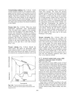
10.2.8 High load beam axle leaf spring sprung
body roll stability (Fig. 10.27)
The factors which influence the resistance to body
roll (Fig. 10.27) are as follows:
a) The centrifugal force acting through the centre
of gravity of the body load.
b) The arm length from the centre of load to the
effective roll centre h
1
or h
2
.
c) The spring stiffness in Newtons/metre of verti-
cal spring deflection.
d) The distance between the centres of both
springs known as the spring stability base t
s
.
e) The distance between road wheel centres known
as the tyre stability base t
w
.
Considering the same side force acting through
the centre of gravity of the body load and similar
spring stiffness for both under- and over-slung
springs (Fig. 10.27), two fundamental observations
can be made.
Firstly it can be seen (Fig. 10.27) that with over-
slung springs the body roll centre RC
1
is much
higher than that for underslung springs RC
2
and
therefore the overslung springs provide a smaller
overturning arm length h
1
as opposed to h
2
for the
underslung springs. As a result, the high roll centre
with the small overturning arm length offers
a greater resistance to body roll than a low roll
centre with a long overturning arm.
Secondly it can be seen (Fig. 10.27) that the
triangular projection lines produced from the centre
of gravity through the centres of the springs to
Fig. 10.26 Semi-trailing arm
Fig. 10.27 Effects of under- and over-slung springs on
the roll centre height
379
the ground provide a much wider spring stability
base for the high mounted springs compared to
the low mounted underslung springs. In fact the
overslung spring centre projection lines nearly
approach the tyre stability base width t
w
which
is the widest possible for such an arrangement
without resorting to outboard spring seats.
10.2.9 Rigid axle beam suspension
(Fig. 10.28(a±d))
An axle beam suspension is so arranged that both
wheel stub axles are rigidly supported by a com-
mon transverse axle beam member which may be a
steered front solid axle beam, a live rear axle hollow
circular sectioned casing or a DeDion tubular axle
beam.
With a rigid axle beam suspension there cannot
be any independent movement of the two stub axles
as is the case with a split swing axle layout. There-
fore any body roll relative to the ground must take
place between the axle beam and the body itself.
Body roll can only take place about a mechanical
pivot axis or about some imaginary axis some-
where near mid-spring height level.
Methods used to locate and control the axle
movement are considered as follows:
Longitudinally located semi-elliptic springs
(Fig. 10.28(a)) When semi-elliptic leaf springs
support the body, the pivoting point or body roll
centre will be roughly at spring-eye level but this
will become lower as the spring camber (leaves
bow) changes from positive upward bowed leaves
when unloaded to negative downward bowed
leaves with increased payload.
Transverse located Panhard rod (Fig. 10.28(b)) The
use of coil springs to support the body requires
some form of lateral body to axle restraint if a
torque tube type axle is to be utilized. This may
be provided by a diagonally positioned Panhard
rod attached at its ends to both the axle and
body. When the body tilts it tends to move side-
ways and either lifts or dips depending which way
the side force is applied. Simultaneously the body
will roll about the mid-position of the Panhard rod.
Diagonally located tie rods (Fig. 10.28(c)) To pro-
vide both driving thrust and lateral support for
Fig. 10.28 (a±d) Body roll centres for rigid beam axle suspensions
380
a helical coil spring live axle layout, a trailing four
link suspension may be adopted which has a pair of
long lower trailing arms which absorb both the
driving and braking torque reactions and a pair of
short upper diagonally located tie rods to control
any lateral movement. Any disturbing side forces
which attempt to make the body tilt sideways will
cause it to roll about a centre roughly in line with
the upper tie rod height.
Transverse Watt linkage (Fig. 10.28(d)) An alter-
native arrangement for controlling the sideways
movement for a coil spring suspension when used
in conjunction with either a live axle or a DeDion
tube is the Watt linkage. Suspension linkages of
this type consist of a pair of horizontal tie rods
which have their outer ends anchored to the body
and their inner ends coupled to a central balance
lever which has its pivot attachment to the axle
beam. If the body is subjected to an overturning
moment it will result in a body roll about the Watt
linkage balance lever pivot point. This instant-
aneous centre is therefore the body roll centre.
10.3 Body roll stability analysis
When a vehicle turns a corner the centrifugal force
produced acts outwards through the centre of grav-
ity of the sprung mass, but it is opposed by the tyre
to ground reaction so that the vehicle will tend to
overturn. An overturning moment is therefore gen-
erated which tends to transfer weight from the
inner wheels to the outside wheels. At the same
time due to the flexibility and softness of the sus-
pension, the body rolls so that in effect it overhangs
and imposes an additional load to the outer wheels.
The opposition to any body roll will be shared
out between the front and rear suspension accord-
ing to their roll resistance. Thus if the front suspen-
sion roll stiffness with an anti-roll bar is twice that
of the rear, then the front wheels will sustain two
thirds of the roll couple while the rear ones only
carry one third.
10.3.1 Body roll couple (Fig. 10.29)
The body roll couple (moment) M consists of two
components:
Centrifugal moment about the roll centre
Fa Nm
Transverse displacement moment wa tan Â
°Wa (Nm)
where1 F = centrifugal side force
a = distance between the centre of
gravity and roll centre
w = unsprung weight
 = angle of body roll
Hence
Total roll movement or couple M Fa WaÂ
(F WÂ) a (Nm)
Fig. 10.29 Body roll centres and roll axis
381
The sum of these couples are resisted by the
springs in proportion to their torsional stiffness at
the front and rear.
Body roll stiffness (Fig. 10.29) The body roll stiff-
ness is defined as the roll couple produced per
degree of body roll.
i:e: Roll stiffness
Roll couple
Roll angle
(Nm=deg)
hence S
M
Â
(Nm=deg)
where S = roll stiffness (Nm/deg)
M = roll couple (Nm)
 = angle of roll (deg)
The fraction of torsional stiffness for the front
and rear suspensions will therefore be:
S
F
S
F
S
F
S
R
Nm=deg
Nm=deg
S
R
S
R
S
R
S
F
where S
F
= fraction of front torsional stiffness
S
R
= fraction of rear torsional stiffness
10.3.2 Body overturning couple (Fig. 10.30)
The centrifugal force F created when a vehicle is
travelling on a circular track acts through the
body's centre of gravity CG at some height h and
is opposed by the four tyre to ground reaction
forces F
1
, F
2
, F
3
and F
4
.
Consequently an overturning couple Fh is pro-
duced which transfers weight W from the inside
wheels to the outer wheels which are spaced the
track width t apart. Thus the overturning couple
will also be equivalent to Wt, that is, Wt Fh.
i:e: Weight transferred W
Fh
t
(N)
It should be noted that the centre of gravity
height h is made up from two measurements; the
distance between the ground and the body roll
centre b and the distance between the roll centre
and the centre gravity a.
Therefore
Total body roll couple Fh F(a b) (N)
M Fa Fb (N)
10.3.3 Body roll weight transfer (Fig. 10.31)
The product Fa is the overturning couple rotating
about the roll centre which causes the body to roll.
This couple is opposed by a reaction couple Rt
where R is the vertical reaction force due to the
weight transfer and t is the wheel track width.
Therefore Rt Fa
R
Fa
t
(N)
This shows that as the distance between the
ground and the body roll centre known as the
couple arm becomes smaller, the overturning couple
and therefore the body roll will also be reduced
in the same proportion. Thus if the couple arm a
is reduced to zero the reaction force R will likewise
approach zero. A small couple is desirable so that
the driver experiences a sense of body roll as
a warning for cornering stability. If both roll centre
and centre of gravity height coincided there would
be no indication to the driver that the lateral forces
acting on the body were reaching the limit of the
tyre to ground sideway grip. Consequently suspen-
sions in which the centre of gravity and the roll
centre are at the same height can cause without
warning a sudden tyre to ground breakaway when
cornering at speed.
10.3.4 Body direct weight transfer couple
(Fig. 10.32)
If the centrifugal force acted through the roll centre
axis instead of through the centre of gravity, a
Fig. 10.30 Overturning couple Fig. 10.31 Body roll weight transfer
382
moment F
b
about the ground would be produced
so that a direct transference of weight from the
inner to the outer wheels occurs. The reaction to
this weight transfer for a track width t is a resisting
moment R
t
which is equal but opposite in sense to
the moment F
b
.
Hence Rt Fb,
therefore R
Fb
t
(N)
If the fore and aft weight distribution is propor-
tional between the front and rear axle roll centres,
the centrifugal force F acting through the roll cen-
tre axis would be split into two forces F
F
and F
R
which act outwards from the front and rear roll
centres.
Thus R
F
F
F
b
F
t
(N)
R
R
F
R
b
R
t
(N)
where R, R
F
and R
R
Total, front and rear
vertical reaction forces
respectively
Thus lowering the body roll centre correspond-
ingly reduces the vertical reaction force R and by
having the roll centre at ground level the direct
weight transfer couple will be eliminated.
Therefore if the roll axis slopes from the ground
upwards from front to rear, all the direct weight
transfer couple will be concentrated on the rear
wheels.
10.3.5 Body roll couple distribution (Fig. 10.29)
The body roll couple on the front and rear tyres is
proportional to the front and rear suspension stiff-
ness fraction.
i.e. Roll couple on front tyres
M
F
S
F
S
F
S
R
(F WÂ)a F
F
h
F
(Nm)
Roll couple on rear tyres
M
R
S
R
S
R
S
F
(F WÂ)a F
R
h
R
(Nm)
Body roll angle The body roll angle may be
defined as the roll couple per unit of roll stiffness
i:e: Total roll angle
Roll couple
Roll stiffness
Nm
Nm=deg
M
S
F
S
R
(deg)
10.3.6 Body roll weight transfer (Fig. 10.29)
The body roll weight transferred may be defined as
the roll couple per unit width of track
i.e. Total roll weight transfer
Roll couple
Track width
Nm
m
hence W
M
t
(N)
:
Front suspension weight transfer
W
F
S
F
S
F
S
R
Â
M
t
(N)
Rear suspension weight transfer
W
R
S
R
S
R
S
F
Â
M
t
(N)
where W, W
F
and W
R
= Total, front and rear
weight transfer
respectively (N)
t = Wheel tract (m)
10.3.7 Lateral (side) force distribution
(Fig. 10.33)
The total lateral resisting forces generated at all
tyre to ground interfaces must equal the centrifugal
Fig. 10.32 Direct weight transfer
Fig. 10.33 Longitudinal weight distributions
383
force acting through the body's centre of gravity.
Thus the fore and aft position of the centre of
gravity determines the weight distribution between
the front and rear wheels and therefore the propor-
tion of cornering force necessary to be generated by
their respective tyres.
If F
F
and F
R
are the front and rear tyre to ground
cornering forces, then taking moments about F
R
F
F
l F
b
Therefore F
F
F
b
l
(N)
F
R
l F
a
Therefore F
R
F
a
l
(N)
Thus the amount of load and cornering force
carried by either the front or rear tyres is propor-
tional to the distance the centre of gravity is from
the one or the other axle. Normally there is slightly
more weight concentrated at the front half of the
vehicle so that greater cornering forces and slip
angles are generated at the front wheels compared
to the rear.
10.3.8 Comparison of rigid axle beam and
independent suspension body roll stiffness
(Fig. 10.24)
A comparison between roll stiffness of both rigid
axle beam and independent suspension can be
derived in the following manner:
Consider the independent suspension (Fig.
10.34(a)). Let the centrifugal force F act through
the centre of gravity CG at a height h above the roll
centre RC. The overturning couple Fh produced
must be equal and opposite to the reaction couple
Wt
w
created by a reduction in the inside wheel
reaction ÀW and a corresponding increase in the
outside wheel reaction W between the effective
spring span t
w
.
If the vertical spring stiffness is S N/m and the
vertical deflection at the extremes of the spring
span is x m then the angle of body roll Y degrees
can be derived as follows:
tan Â
x
t
w
=2
2x
t
w
(1)
Weight transfer W xS
Therefore Overturning couple Fh
and Reaction couple Wt Sxt
(since W Sx)
; Fh Sxt
w
or x
Fh
t
w
S
(2)
From (1) tan Â
2x
t
w
but x
Fh
St
w
so tan Â
2
t
Fh
St
w
When  is small, tan  ° Â
; Â
2Fh
St
w
2
(3)
This formula shows that the body roll angle is
proportional to both centrifugal force F and the
couple arm height h but it is inversely proportional
to both the spring stiffness k and the square of the
spring span t
w
2
, which in this case is the wheel
track.
i:e: Â G F, Â G h, Â G
1
S
and  G
1
t
w
2
Fig. 10.34 (a and b) Comparison of rigid and independent suspension body roll stiffness
384
A similar analysis can be made for the rigid axle
beam suspension (Fig. 10.34(b)), except the spring
span then becomes the spring base t
s
instead of t
w
.
Because the spring span for a rigid axle beam sus-
pension is much smaller than for an independent
suspension (t
w
2
) t
s
2
), the independent wide spring
span suspension offers considerably more roll resist-
ance than the narrow spring span rigid axle beam
suspension and is therefore preferred for cars.
10.4 Anti-roll bars and roll stiffness (Fig. 10.35)
10.4.1 Anti-roll bar function
A torsion anti-roll bar is incorporated into the
suspension of a vehicle to enable low rate soft
springs to be used which provides a more comfort-
able ride under normal driving conditions. The
torsion bar does not contribute to the suspension
spring stiffness (the suspension's resistance to ver-
tical deflection) as its unsprung weight is increased
or when the driven vehicle is subjected to dynamic
shock loads caused possibly by gaps or ridges
where concrete sections of the road are joined
together. However, the anti-roll bar does become
effective if one wheel is raised higher than the other
(Fig. 10.35) as the vehicle passes over a hump in the
road or the body commences to roll while corner-
ing. Under these conditions, the suspension spring
stiffness (total spring rate) increases in direct pro-
portion to the relative difference in deflection of
each pair of wheels when subjected to the bump
and rebound of individual wheels or body roll
when the vehicle is moving on a circular path.
10.4.2 Anti-roll bar construction (Fig. 10.36)
Generally the anti-roll bar is formed from a medium
carbon steel solid circular sectioned rod which is
positioned transversely and parallel to the track (Fig.
10.36) so that it nearly spans the distance between
the road wheels (Fig. 10.35). The bar is bent at both
ends in right angles to form cracked arms. These
arms can then be actuated by short link rods
attached to the unsprung portion of the suspension
such as the axle beam or transverse wishbone arms
for independent suspension. The main transverse
span of the rod is supported by rubber bearings
positioned on the inside of the cranked arms at
each end. These bush bearings are either mounted
directly onto the body structure when incorporated
Fig. 10.35 Transverse double wishbone coil spring independent suspension with anti-roll bar
Fig. 10.36 Transverse double wishbone torsion bar independent suspension with anti-roll bar
385
on cars (Fig. 10.35) or indirectly for commercial
vehicles (Fig. 10.39) on short vertical arms which
provide a swing attachment to the chassis.
10.4.3 Anti-roll bar operating principle
When a pair of road wheels supported on an axle
travel over a bumpy road one or other wheel will lift
and fall as they follow the contour of the road
surface. If the springs were relatively hard, that is
they have a high spring rate, then the upthrust
caused by the bumps would be transmitted to the
body which would then lift on the side being dis-
turbed. Thus the continuous vertical deflection of
either wheel when the vehicle moves forward would
tend to make the body sway from side to side pro-
ducing a very uncomfortable ride. On the other hand
if softer springs were used for the suspension, the
small road surface irregularities would be adequately
absorbed by the springs and dampers, but when
cornering there would be insufficient spring stiffness
to resist the overturning moment; this would there-
fore permit excessive body roll which could not be
tolerated. Incorporating an anti-roll bar with rela-
tively soft suspension springs mostly overcomes the
difficulties discussed and therefore greatly improves
the vehicle's ride. This is possible because the soft
springs improve the suspension's response on good
straight roadways (Fig. 10.37), with the benefits of
the anti-roll bar automatically increasing the suspen-
sion roll stiffness when the vehicle is cornering.
10.4.4 Anti-roll bar action caused by the body
rolling (Fig. 10.39(a and b))
When cornering, the centrifugal force acting
through the centre of gravity of the sprung body
produces an overturning moment created by its
offset to the body's roll centre which will therefore
tend to make the body roll (Fig. 10.39(a and b)).
The rolling body will tilt the transverse span of the
roll bar with it so that the cranked arms on the
outside wheel to the turn will be depressed down-
ward, whereas the cranked arm on the opposite end
near the inside wheel to the turn will tend to rise.
The consequence of this misalignment of the anti-
roll bar arms is that the two cranked arms will
rotate in opposite directions to each other and so
transmit a torque from the inside wheel which is
subjected to less load to the outside wheel which is
now more heavily loaded. The effect of the tor-
sional wind-up in the bar is that it tries to rotate
the outside wheel cranked arm and since the arm is
attached to the axle or indirectly to the wishbone
arm it cannot move. The alternative is for the roll
bar and the rubber bearing mount near the outside
wheel to lift in proportion to the degree of twisting
torque. It therefore counteracts some of the down-
ward push due to the increase in weight to the
outside wheel and as a result stiffens the roll resist-
ance of the springing on the outside wheel as a
whole. Consequently a larger slip angle is generated
on the front outside wheel relative to the rear
wheel, and as a result, the vehicle will develop a
small initial but progressive understeer tendency
approximately proportional to the amount the
body rolls (Fig. 10.38).
10.4.5 Anti-roll bar action caused by single wheel
lift (Fig. 10.39(c and d))
If one of a pair of axle wheels lifts as it climbs over a
bump (Fig. 10.39(c)) in the road, then the vertical
Fig. 10.37 Relationship of body roll and suspension
spring and anti-roll bar stiffness
Fig. 10.38 Relationship of body roll and the understeer
tendency with and without an anti-roll bar
386
deflection of the wheel and spring raises and rotates
the anti-roll bar's cranked arm on that side so that
the transverse span of the bar is twisted. The bar is
therefore subjected to a torque which is propor-
tional to its angle of rotation.
This twisting torque is transferred to the oppos-
ite cranked arm which then applies a downward
force onto the axle and wheel. However, because
the wheel cannot sink into the ground, the reaction
occurs on the rubber bearing mount arm which
therefore tends to lift up the side of the chassis on
the opposite side to the vertically deflected wheel.
As a result, both sides of the chassis (body) will
have been raised, thereby enabling the vehicle's
body to remain upright instead of tilting to one
side. Similarly, if the opposite wheel hits an
obstacle in the road (Fig. 10.39(d)), the torsional
wind-up of the bar transfers an upward thrust to the
other side, which again tends to lift the chassis on
the undisturbed wheel side and so maintains
the sprung chassis and body on an even keel
(Fig. 10.39(c)).
10.5 Rubber spring bump or limiting stops
10.5.1 Bump stop function
(Figs 10.40 and 10.42)
Suspension bump and body roll control depends
upon the stiffness of both the springs and anti-roll
bar over the normal operating conditions, but if the
suspension deflection approaches maximum bump
or roll the bump stop (Fig. 10.40(a, b, c and d))
becomes active and either suddenly or progres-
sively provides additional resistance to the full
deflection of the wheel and axle relative to the
body (Fig. 10.42). The bump stop considerably
stiffens the resisting spring rate near the limit of
its vertical movement to prevent shock impact and
damage to the suspension components. The stop
also isolates the sprung and unsprung members of
the suspension under full deflection conditions so
that none of the noise or vibrations are transmitted
through to the body structure. In essence the bump
stop enables an anti-roll bar to be used which has
a slightly lower spring rate, therefore permitting
Fig. 10.39 (a±d) Anti-roll bar action
387
a more cushioned ride for a moderate degree of
body roll.
10.5.2 Bump stop construction (Fig. 10.40(a±d))
Bump stops may be considered as limiting springs
as they have elastic properties in compression
similar to other kinds of spring materials. Solid
and hollow spring stops are moulded without
reinforcement from natural rubber compound
containing additives to increase the ozone resist-
ance. The deflection characteristics for a given
size of rubber stop spring are influenced by the
hardness of the rubber, this being controlled to
a large extent by the proportion of sulphur and
carbon black which is mixed into the rubber com-
pound. The most common rubber compound
hardness used for a rubber spring stop is quoted
as a shore hardness of 65; other hardness ranging
from 45 to 75 may be selected to match a par-
ticular operating requirement. A solid cylindrical
rubber block permits only 20% deflection when
loaded in compression, whereas hollow rubber
spring stops have a maximum deflection of 50±75%
of their free height. The actual amount of deflec-
tion for a given spring stop height and response
to load will depend upon a number of factors
such as the rubber spring stop size, outer profile,
wall thickness, shape of inner cavities, hardness of
rubber compound and the number of convolution
folds.
Bump rubber spring stops may be solid and
conical in shape or they may be hollow and cylin-
drical or rectangular shaped with a bellow profile
(Fig. 10.40(a, b, c and d)) having either a single,
double or triple fold (known as convolutions). The
actual profile of the rubber bump stop selected will
depend upon the following:
1 How early in the deflection or load operating
range of the suspension the rubber begins to
compress and become active.
2 Over what movement and weight change the
bump stop is expected to contribute to the sud-
den or progressive stiffening of the suspension so
that it responds to any excessive payload, impact
load and body roll.
10.5.3 Bump stop characteristics
(Figs 10.41 and 10.42)
The characteristics of single, double and triple con-
volution rubber spring stops, all using a similar
rubber hardness, are shown in Fig. 10.41. It can
be seen that the initial deflection for a given load is
large but towards maximum deflection there is very
little compression for a large increase in load. The
relation between load and deflection for bump is
not quite the same on the release rebound so that
the two curves form what is known as a hysteresis
loop. The area of this loop is a measure of the
energy absorbed and the internal damping within
Fig. 10.40 (a±d) Suspension bump stop limiter arrangements
388
the rubber in one cycle of compression and expan-
sion of the rubber spring stop. For hollow rubber
spring stops they always end in a point; this means
for any load change there will be some spring
deflection.
Fig. 10.42 shows how the bump spring stop
deviates from the main spring load-deflection
curve at about two-thirds maximum deflection
and that the resultant stiffness (steepness of curve)
of the steel spring, be it leaf, coil or torsion bar, and
that of the bump spring stops considerably
increases towards full load.
10.6 Axle location
10.6.1 Torque arms (Figs 10.28(c) and 10.44)
Torque arms, sometimes known as radius arms
or rods, are mounted longitudinally on a vehicle
between the chassis/body structure and axle or
unsprung suspension member. Its purpose is to
permit the axle to move up and down relative to
the sprung chassis/body and to maintain axle align-
ment as the torque arm pivots about its pin, ball
or conical rubber joint. Sometimes the upper
torque rods are inclined diagonally to the vehicle's
lengthwise axis to provide lateral axle stability
(Figs 10.28(c) and 10.44). These arms form the
link between the unsprung suspension members
and the sprung chassis/body frame and are there-
fore able to transmit both driving and braking
forces and to absorb the resulting torque reactions.
10.6.2 Panhard rod (Fig. 10.28(b))
Panhard rods, also known as transverse control
rods or arms, are positioned across and between
both rear wheels approximately parallel to the axle
(Fig. 10.28(b)). One end of the rod is anchored to
one side of the axle span while the other end is
anchored to the body structure; both attachments
use either pin or ball type rubber joints. A Panhard
rod restrains the body from moving sideways as the
vehicle is subjected to lateral forces caused by side-
winds, inclined roads and centrifugal forces when
cornering. When the body is lowered, raised or
tilted relative to the axle, the Panhard rod is able
to maintain an approximate transverse axle align-
ment (Fig. 10.28(b)) relative to the chassis/body
thus relieving the suspension springs from side
loads.
10.6.3 Transverse located Watt linkage
(Fig. 10.43(a, b and c))
A Watt linkage (Fig. 10.43) was the original
mechanism adopted by James Watt to drive his
beam steam engine. This linkage is comprised of
two link rods pivoting on the body structure at
their outer ends and joined together at their inner
ends by a coupler or equalizing arm which is
pivoted at its centre to the middle of the rear axle.
When in mid-position the link rods are parallel
whereas the equalizing arm is perpendicular to
both (Fig. 10.43(b)).
If vertical movement of the body occurs either
towards bump (Fig. 10.43(c)) or rebound (Fig.
10.43(a)) the end of the link rods will deviate an
equal amount away from the central pivot point of
the coupling arm. Thus the left hand upper link rod
Fig. 10.41 Characteristics of hollow rubber single,
double and triple convolute progressive bump stops
Fig. 10.42 Combined characteristics of suspension
spring and rubber bump stops
389
will tend to pull towards the left and the right hand
lower link rod will apply an equal pull towards the
right. The net result will be to force the equalizing
arm to rotate anticlockwise to accommodate the
inclination to the horizontal of both link rods. If
the left hand link rod were made the lower link and
the right hand rod the upper link, then the direction
of tilt for the equalizing arm would now become
clockwise.
For moderate changes in the inclination of the
link rods, the body will move in a vertical straight
line, thus maintaining a relatively accurate body to
axle lateral alignment. Excessive up and down
movement of the body will cause the pivot centre
to describe a curve resembling a rough figure eight,
a configuration of this description being known as
a lemniscoid (Fig. 10.43(b)).
Under body roll conditions when cornering,
the whole body relative to the axle and wheels will
be restrained to rotate about the equalizing
arm pivot centre at mid-axle height; this point
therefore becomes the roll centre for the rear end
of the body.
A similar Watt linkage arrangement can be
employed longitudinally on either side of the wheels
to locate the axle in the fore and aft direction.
10.7 Rear suspension arrangements
10.7.1 Live rigid axle rear suspension
Suspension geometry characteristics of a live axle
are as follows:
1 Wheel camber is zero irrespective if the vehicle is
stationary or moving round a bend in the road.
2 If one wheel moves over a hump or dip in the
road then the axle will tilt causing both wheels to
become cambered.
3 Because both wheels are rigidly joined together
the wheel track remains constant under all driv-
ing conditions.
4 Because the axle casing, half shafts and final
drive are directly supported by the wheels, the
unsprung weight of a live axle is very high.
5 With a live rigid axle, which is attached to the
body by either leaf or coil springs, the body will
tilt about some imaginary roll centre roughly
mid-way between the upper and lower spring
anchorage points.
6 Horizontal fore and aft or lateral body location
is achieved by using the leaf springs themselves
as restraining members or, in the case of coil
springs which can only support the vehicle's ver-
tical load and therefore cannot cope with driving
thrust and side loads, horizontally positioned
control rods.
Without accurate control of horizontal body
movement relative to the axle casing caused by
vertical deflection of the springs or longitudinal
and transverse forces, the body's weight distribu-
tion would be unpredictable which would result in
poor road holding and steering response.
Hotchkiss drive suspension (Fig. 10.84(a)) This is
the conventional semi-elliptic spring suspension
which has each spring positioned longitudinally
on each side of the axle and anchored at the front
end directly to a spring hanger attached to the body
structure and at the rear end indirectly via swing
shackle plates to the rear spring hangers, the axle
being clamped to the springs somewhere near their
mid-span position. Thus fore and aft driving and
braking forces are transmitted through the front
half of the springs and lateral forces are accommo-
dated by the rigidity of the spring leaves and spring
anchorage.
Four link coil spring live axle rear suspension
(Fig. 10.44) Substituting coil springs for semi-elliptic
springs requires a separate means of locating
and maintaining body and axle alignment when
Fig. 10.43 (a±c) Transversely located Watt linkage
390
subjected to longitudinal and transverse forces
caused by spring deflection, body roll or driving
and braking thrust loads.
The locating links are comprised of a pair of long
trailing lower arms and a pair of short diagonally
positioned upper torque arms (Fig. 10.44). Rubber
pin joints secure the forward ends of the arms to
the body structure but the lower rear ends are
attached underneath the axle tubes as far apart as
possible and the upper short torque arms attached
much closer together onto the final drive housing.
The coil springs are mounted between the upper
body structure and the lower pressed steel trailing
arms. These springs only provide vertical support
and cannot restrain any horizontal movement on
their own. Spring deflection due to a change in
laden weight causes both sets of arms to swivel
together, thereby preventing the axle assembly
rotating and possibly making the universal joints
operate with very large angles. Both driving and
braking thrust are transmitted through the lower
trailing arms which usually are of a length equal to
roughly half the wheel track so that when the arms
swing the change in wheelbase is small. The upper
arms are normally inclined at 45
to the car's centre
line axis so that they can absorb any axle reaction
torque tending to rotate the axle, and at the same
time prevent relative lateral movement between the
body and axle. Body roll or axle tilt are permitted
due to the compliance of the rubber pin joints.
A relatively high roll centre is obtained which
will be roughly at the upper torque arm height.
Torque tube rear wheel drive suspension (Fig. 10.45)
One of the major problems with the Hotchkiss
drive layout is that the axle torque reaction tends
to spin the axle casing when transmitting drive
torque in the opposite direction to the rotating
wheels and when braking to twist the axle casing
in the same direction as the revolving wheels. The
result is a considerably distorted semi-elliptic
spring and body to axle misalignment. To over-
come this difficulty, a rigid tube may be bolted to
the front of the final drive pinion housing
which extends to the universal joint at the rear of
the gearbox or a much shorter tube can be used
which is supported at its front end by a rubber pin
or ball joint attached to a reinforcing cross-member
Fig. 10.44 Four link coil spring live axle rear suspension
Fig. 10.45 Torque tube with trailing arm and transverse Watt linkage live axle rear suspension
391