Advanced Vehicle Technology Episode 3 Part 2 pdf
Bạn đang xem bản rút gọn của tài liệu. Xem và tải ngay bản đầy đủ của tài liệu tại đây (307.76 KB, 20 trang )
to its standard height. The ability for the spool
valve to respond quickly and close off the exhaust
valve is due to the right hand disc valve being open.
Thus fluid in the unrestricted passage is permitted
to push open the right hand disc valve, this allows
fluid to readily move through both the restricted
and unrestricted passages from the right to left
hand diaphragm chamber. Immediately the tor-
sional wind-up of the control rod due to the anti-
roll bar rotation causes the spool valve to shift to
the neutral cut-off position.
Manual height correction A manual control lever
is provided inside the car, the lever being connected
by actuating rods to the front and rear height cor-
rection units. Its purpose is to override the normal
operation of the spool valve and to allow the driver
to select five different positions:
Normal Ð this is the standard operating
position
High or low Ð two extreme positions
Two positions Ð intermediate between normal
and high
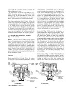
10.10.1 Hydropneumatic self-levelling spring unit
(Figs 10.73(a and b) and 10.74(a, b and c))
This constant height spring unit consists of two
sections;
1 a pneumatic spring and hydraulic damper
system,
2 a hydraulic constant level pump system.
An approximately constant frequency of vibration
for the sprung mass, irrespective of load, is obtained
by having two gas springs, a main gas spring, in
which the gas is contained behind a diaphragm,
and a correction gas reservoir spring (Fig. 10.73(a,
b and c)). The main spring is controlled by displacing
fluid from the upper piston chamber to the spring
diaphragm chamber and the correction gas spring is
operated by the lower piston chamber discharging
fluid into the reservoir gas spring chamber.
The whole spring unit resembles a telescopic
damper. The cylindrical housing is attached to the
sprung body structure whereas the piston and inte-
gral rod are anchored to either the unsprung sus-
pension arm or axle.
The housing unit comprises four coaxial
cylinders;
1 the central pump plunger cylinder with the lower
conical suction valve and an upper one way
pump outlet disc valve mounted on the piston,
2 the piston cylinder which controls the gas springs
and damper valves,
3 the inner gas spring and reservoir chamber cylin-
der,
4 the outer gas spring chamber cylinder which is
separated from hydraulic fluid by a flexible dia-
phragm.
The conical suction valve which is mounted in
the base of the plunger's cylinder is controlled by
a rod located in the hollow plunger. A radial bleed
port or slot position about one third of the way
down the plunger controls the height of the spring
unit when in service.
The damper's bump and rebound disc valves are
mounted in the top of the piston cylinder and an
emergency relief valve is positioned inside the hol-
low pump plunger at the top.
The inner gas spring is compressed by hydraulic
fluid pressure generated by the retraction of the
space beneath the piston.
The effective spring stiffness (rate) is the sum of
the stiffnesses of the two gas springs which are
interconnected by communication passages. There-
fore the stiffness increase of load against deflection
follows a steeper curve than for one spring alone.
Gas spring and damper valve action (Fig. 10.73
(a and b)) There are two inter-related cycles; one
is effected by the pressure generated above the
piston and the other relates to the pressure devel-
oped below the piston.
When, during bump travel (Fig. 10.73(a)), the
piston and its rod move upwards, hydraulic fluid
passes through the damper bump valve to the outer
annular main gas spring chamber and compresses
the gas spring. Simultaneously as the load beneath
the piston reduces, the inner gas spring and reser-
voir expand and fluid passes through the transfer
port in the wall to fill up the enlarging lower piston
chamber cylinder. Thus the deflection of the dia-
phragm against the gas produces the elastic resili-
ence and the fluid passing through the bump valve
slows down the transfer of fluid to the gas spring so
that the bump vibration frequency is reduced.
On rebound (Fig. 10.73(b)) fluid is displaced
from the outer spring chamber through the damper
rebound valve into the upper piston cylinder and at
the same time fluid beneath the piston is pushed
out of the lower piston chamber into the inner gas
spring chamber where it now compresses the inner
gas spring.
Likewise fluid which is being displaced from the
main gas spring to the upper piston chamber
412
experiences an increased resistance due to the
rebound valve passage restriction so that the fluid
transfer is achieved over a longer period of time.
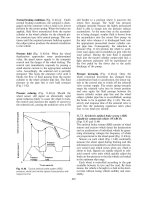
Pump self-levelling action (Figs 10.74(a, b and c)
and 10.73(a and b)) The movement of the piston
within its cylinder also causes the pump plunger to
be actuated. During bump travel (Figs 10.73(a) and
10.74(a)) the plunger chamber space is reduced,
causing fluid to be compressed and pushed out
from below to above the piston via the pump outlet
valve. On rebound (Fig. 10.74(c)), the volume
beneath the piston is replenished. However, this
action only takes place when the piston and rod
have moved up in the cylinder beyond the designed
operating height.
The conical suction valve, which is mounted in
the base of the plunger's cylinder and is controlled
Fig. 10.73 (a and b) Exaggerated diagrams illustrating the self-levelling action of a hydropneumatic suspension unit
413
by a rod located in the hollow plunger, and also a
radial bleed port or slot, positioned about one third
of the way down the plunger, control the height of
spring unit when in service.
The damper's bump and rebound disc valves are
mounted in the top of the piston cylinder and an
emergency relief valve is positioned inside the hol-
low pump plunger at the top.
The inner gas spring is compressed by hydraulic
fluid pressure generated by the retraction of the
space beneath the piston.
The pumping action is provided by the head of
the plunger's small cross-sectional area pushing
down onto the fluid in the pump chamber during
the bump travel (Fig. 10.74(a)). This compels the
fluid to transfer through the pump outlet valve into
the large chamber above the piston. The pressure of
the fluid above the piston and that acting against
the outer gas spring diaphragm is the pressure
necessary to support the vehicle's unsprung mass
which bears down on the spring unit. During
rebound travel (Fig. 10.74(c)), the fluid volume in
the pump chamber increases while the volume
beneath the piston decreases. Therefore some of
the fluid in the chamber underneath the piston
will be forced into the inner gas spring chamber
Fig. 10.74 (a±c) Self-levelling hydropneumatic suspension
414
against the trapped gas, whilst the remainder of the
excess fluid will be transferred from the lower pis-
ton chamber through a passage that leads into an
annular chamber that surrounds the pump chamber.
The pressurized fluid surrounding the pump chamber
will then force open the conical suction valve permit-
ting fluid to enter and fill up the pump chamber as it
is expanded during rebound (Fig. 10.74(c)). This
sequence of events continues until the piston has
moved far enough down the fixed pump plunger to
expose the bleed port (or slot) in the side above the
top of the piston (Figs 10.74(c) and 10.73(b)).
At this point the hollow plunger provides a con-
necting passage for the fluid so that it can flow
freely between the upper piston chamber and the
lower plunger chamber. Therefore, as the piston
rod contracts on bump, the high pressure fluid in
the plunger chamber will be discharged into the
upper piston chamber by not only the pump outlet
valve but also by the plunger bleed port (slot) (Fig.
10.74(a)). However, on the expansion stroke some
of the pressurized fluid in the upper piston chamber
can now return to the plunger chamber and thereby
prevents the conical suction valve opening against
the pressure generated in the lower piston chamber
as its volume decreases. The plunger pumping
action still continues while the spring unit height
contracts, but on extension of the spring unit (Fig.
10.74(c)) the fluid is replenished not from the lower
piston chamber as before but from the upper piston
chamber so that the height of the spring unit
cannot increase the design spring unit length.
When the spring unit is extended past the design
height the underside of the piston increases the
pressure on the fluid in the reservoir chamber and
at the same time permits fluid to bleed past the
conical suction valve into the plunger chamber. If
the spring unit becomes fully extended, the suction
valve is lifted off its seat, enabling the inner spring
chamber to be filled with fluid supplied from the
lower piston chamber and the plunger chamber.
10.11 Commercial vehicle axle beam location
An axle beam suspension must provide two degrees
of freedom relative to the chassis which are as
follows:
1 Vertical deflection of axle due to static load or
dynamic bump and rebound so that both wheels
can rise and fall together.
2 Transverse axle twist to permit one wheel to rise
while the other one falls at the same time as the
vehicle travels over uneven ground.
In addition, the suspension must be able to
restrain all other axle movements relative to the
chassis and the construction should be such that it
is capable of supporting the forces and moments
that are imposed between the axle and chassis.
Both vertical axle deflection and transverse axle
tilt involve some sort of rotational movement of the
restraining and supporting suspension members, be
they the springs themselves or separate arm mem-
bers they must be able to swing about some pivot
point.
The two basic methods of providing articulation
of suspension members is the pivot pin joint and
the ball and socket joint. These joints may either be
rigid metal, semi-rigid plastic or flexible rubber,
their selection and adoption being determined by
the vehicle's operating requirements.
To harness the axle so that it is able to transfer
accelerating effort from the wheels to the chassis
and vice versa, the suspension must have built-in
members which can absorb the following forces
and moments;
1 vertical forces caused by vehicle laden weight,
2 longitudinal forces caused by tractive and brak-
ing effort,
3 transverse forces caused by centrifugal force,
side slopes and lateral winds,
4 rotational torque reactions caused by driving
and braking efforts.
10.11.1 Multi-leaf spring eye support
(Fig. 10.75(a, b and c))
Axle location by multi-leaf springs relies on the
spring eyes having sufficient strength and support
to cope with the vehicle's laden weight driving and
braking thrust and lateral forces. Springs designed
Fig. 10.75 Spring eye protection
415
for cars and light vans generally need only a single
main leaf (Fig. 10.75(a)) wrapped around the bush
and shackle pin alone, but for heavy duty condi-
tions it is desirable to have the second leaf wrapped
around the main leaf to give it additional support.
If a second leaf were to be wrapped tightly
around the main leaf eye, then there could not be
any interleaf sliding which is essential for multi-leaf
spring flexing to take place. As a compromise for
medium duty applications, a partial or half-
wrapped second leaf may be used (Fig. 10.75(b))
to support the main leaf of the spring. This
arrangement permits a small amount of relative
lengthwise movement to occur when the spring
deflects between bump and rebound. For heavy
duty working conditions, the second leaf may be
wrapped loosely in an elongated form around the
main lead eye (Fig. 10.75(c)). This allows a degree
of relative movement to occur, but at the same time
it provides backup for the main leaf eye. If the main
leaf should fracture at some point, the second leaf
is able to substitute and provide adequate support;
it therefore prevents the axle becoming out of line
and possibly causing the vehicle to steer out of
control.
10.11.2 Transverse and longitudinal spring, axle
and chassis attachments (Figs 10.76±10.83)
For small amounts of transverse axle twist, rubber
bushes supporting the spring eye-pins and shackle
plates are adequate to absorb linkage misalign-
ment, and in extreme situations the spring leaves
themselves can be made to distort and accommo-
date axle transverse swivel relative to the chassis
frame. In certain situations where the vehicle is
expected to operate over rough ground additional
measures may have to be taken to cope with very
large degrees of axle vertical deflection and trans-
verse axle tilt.
The semi-elliptic spring may be attached to the
chassis and to the axle casing in a number of ways
to accommodate both longitudinal spring leaf cam-
ber (bow) change due to the vehicle's laden weight
and transverse axle tilt caused by one or other
wheel rising or falling as they follow the contour
of the ground.
Spring leaf end joint attachments may be of the
following kinds;
a) cross-pin anchorage (Fig. 10.76),
b) pin and fork swivel anchorage (Fig. 10.77),
c) bolt and fork swivel anchorage (Fig. 10.78),
d) pin and ball swivel anchorage (Fig. 10.79),
e) ball and cap swivel anchorage (Fig. 10.80).
Alternatively, the spring leaf attachment to the
axle casing in the mid-span region may not be a
direct clamping arrangement, but instead may be
through some sort of pivoting device to enable a
relatively large amount of transverse axle tilt to be
Fig. 10.76 (a and b) Main spring to chassis hinged
cross-pin anchorage
Fig. 10.77 Main spring to chassis pin and fork swivel
anchorage
Fig. 10.78 Main spring to chassis bolt and fork swivel
anchorage
416
accommodated. Thus transverse axle casing to
spring relative movement can be achieved by either
a pivot pin (Fig. 10.81) or a spherical axle saddle
joint (Fig. 10.82) arrangement. Likewise for reac-
tive balance beam shackle plate attachments the
joints may also be of the spherical ball and cap
type joint (Fig. 10.83).
10.12 Variable rate leaf suspension springs
The purpose of the suspension is to protect the
body from the shocks caused by the vehicle moving
over an uneven road surface. If the axle were bolted
directly to the chassis instead of through the media
of the springs, the vehicle chassis and body would
try to follow a similar road roughness contour and
would therefore lift and fall accordingly. With
increased speed the wheel passing over a bump
would bounce up and leave the road so that the
grip between the tyre and ground would be lost.
Effectively no tractive effort, braking retardation
or steering control could take place under these
conditions.
A suspension system is necessary to separate the
axleandwheelsfromthechassissothatwhenthe
wheels contact bumps in the road the vertical deflec-
tion is absorbed by the elasticity of the spring mater-
ial, the strain energy absorbed by the springs on
impact being given out on rebound but under
damped and controlled conditions. The deflection
of the springs enables the tyres to remain in contact
with the contour of the road under most operating
conditions. Consequently the spring insulates the
Fig. 10.79 (a±c) Main spring to chassis pin and
spherical swivel anchorage
Fig. 10.80 (a±c) Main spring to chassis spherical swivel
anchorage
Fig. 10.81(a and b) Axle to spring pivot pin seat mounting
Fig. 10.82 Axle to spring spherical seat mounting
Fig. 10.83 Tandem axle balance beam to shackle plate
spherical joint
417
body from shocks, protects the goods being trans-
ported and prevents excessively high stresses being
imposed on the chassis which would lead to fatigue
failure. It also ensures that the driver is cushioned
from road vibrations transmitted through the wheels
and axle, thereby improving the quality of the ride.
The use of springs permits the wheels to follow the
road contour and the chassis and body to maintain
a steady mean height as the vehicle is driven along
the road. This is achieved by the springs continuously
extending and contracting between the axle and
chassis, thereby dissipating the energy imparted to
the wheels and suspension assembly.
A vehicle suspension is designed to permit the
springs to deflect from an unladen to laden condi-
tion and also to allow further deflection caused by
a wheel rapidly rolling over some obstacle or pot
hole in the road so that the impact of the unsprung
axle and wheel responds to bump and rebound
movement. How easily the suspension deflects
when loaded statically or dynamically will depend
upon the stiffness of the springs (spring rate) which
is defined as the load per unit deflection.
i:e: Spring stiffness or rate S
Applied load
Deflection
W
x
(N=m)
A low spring stiffness (low spring rate) implies
that the spring will gently bounce up and down in
its free state which has a low natural frequency of
vibration and therefore provides a soft ride.
Conversely a high spring stiffness (high spring
rate) refers to a spring which has a high natural
frequency of vibration which produces a hard
uncomfortable ride if it supports only a relatively
light load. Front and rear suspensions have natural
frequencies of vibration roughly between 60 and 90
cycles per minute. The front suspension usually has
a slightly lower frequency than the rear. Typical
suspension natural frequencies would be 75/85
cycles per minute for the front and rear respec-
tively. Spring frequencies below 60 cycles per min-
ute promote car sickness whereas frequencies
above 90 cycles per minute tend to produce harsh
bumpy rides. Increasing the vehicle load or static
deflection for a given set of front and rear spring
stiffness reduces the ride frequency and softens the
ride. Reducing the laden vehicle weight raises the
frequency of vibration and the ride hardness.
Vehicle laden weight, static suspension deflection,
spring stiffness and ride comfort are all inter-related
and produce conflicting characteristics.
For a car there is not a great deal of difference
between its unladen and fully laden weight; the
main difference being the driver, three passengers,
luggage and full fuel tank as opposed to maybe
a half full fuel tank and the driver only. Thus if
the car weighs 1000 kg and the three passengers,
luggage and full fuel tank weigh a further 300 kg, the
ratio of laden and unladen weight will be 1300/1000
1.3:1. Under these varying conditions, the static
suspension deflection can be easily accommodated
by soft low spring rates which can limit the static
suspension deflection to a maximum of about
50 mm with very little variation in the natural
frequency of vibration of the suspension system.
For a heavy goods vehicle, if the unladen weight
on one of the rear axles is 2000 kg and its fully
laden capacity is 10 000 kg, then the ratio of laden
to unladen weight would be 10 000/2000 5:1. It
therefore follows that if the spring stiffness for the
axle suspension is designed to give the best ride
with the unladen axle, a soft low spring rate
would be required. Unfortunately, as the axle
becomes fully laden, the suspension would deflect
maybe five times the unladen static deflection of,
say, 50 mm which would amount to 250 mm. This
large change from unladen to fully laden chassis
height would cause considerable practical compli-
cations and therefore could not be acceptable.
If the suspension spring stiffnesses were to be
designed to give the best ride when fully laden,
the change in suspension deflection could be
reduced to something between 50 and 75 mm
when fully laden. The major disadvantage of utiliz-
ing high spring rates which give near optimum ride
conditions when fully laden would be that when the
axle is unladen, the stiffness of the springs would be
far too high so that a very hard uncomfortable ride
would result, followed by mechanical damage to
the various chassis and body structures.
It is obvious that a single spring rate is unsuitable
and that a dual or progressive spring rate is essen-
tial to cope with large variations in vehicle payload
and to restrict the suspension's vertical lift or fall to
a manageable amount.
10.12.1 Dual rate helper springs (Fig. 10.84(a))
This arrangement is basically a main semi-elliptic
leaf spring with a similar but smaller auxiliary
spring located above the main spring. This spring
is anchored to the chassis at the front via a shackle
pin to the spring hanger so that the driving thrust
can be transmitted from the axle and wheel to the
chassis. The rear end of the spring only supports
418
Fig. 10.84 (a±g) Variable rate leaf spring suspension
419
the downward load and does not constrain the fore
and after movement of the spring.
In the unladen state only the main spring supports
the vehicle weight and any payload carried
(Fig. 10.84(a)) is subjected to a relatively soft ride.
Above approximately one third load, the ends of the
auxiliary helper spring contact the abutments
mounted on the chassis. The vertical downward
deflection is now opposed by both sets of springs
which considerably increase the total spring rate and
also restrict the axle to chassis movement. The
method of providing two spring rates, one for lightly
laden and a second for near fully laden condition,
is adopted by many heavy goods vehicles.
10.12.2 Dual rate extended leaf springs
(Fig. 10.84(b))
With this semi-elliptic leaf spring layout the axle is
clamped slightly offset to the mid-position of the
spring. The front end of the spring is shackled to
the fixed hanger, whereas the rear end when
unloaded bears against the outer slipper block.
The full span of the spring is effective when operat-
ing the vehicle partially loaded. A slight progressive
stiffening of the spring occurs with small increases
in load, due to the main spring blade rolling on the
curved slipper pad from the outermost position
towards its innermost position because of the effect-
ive spring span shortening. Hence the first deflec-
tion stage of the spring provides a very small
increase in spring stiffness which is desirable to
maintain a soft ride.
Once the vehicle is approximately one third
laden, the deflection of the spring brings the main
blade into contact with the inner slipper block. This
considerably shortens the spring length and the
corresponding stiffening of the spring prevents
excessive vertical deflection. Further loading of
the axle will make the main blade roll round the
second slipper block, thereby providing the second
stage with a small amount of progressive stiffening.
Suspension springing of this type has been success-
ful on heavy on/off road vehicles.
10.12.3 Progressive multi-leaf helper springs
(Fig. 10.84(c))
The spring span is suspended between the fixed
hanger and the swinging shackle. The spring con-
sists of a stack of leaves clamped together near the
mid-position, with about two thirds of the leaves
bowed (cambered) upward so that their tips con-
tact and support the immediate leaf above it. The
remainder of the leaves bow downward and so do
not assist in supporting the body weight when the
car or van is only partially laden. As the vehicle
becomes loaded, the upper spring leaves will deflect
and curve down on either side of the axle until their
shape matches the first downward set lower leaf.
This provides additional upward resistance to the
normally upward bowed (curved) leaves so that as
more leaves take up the downward bowed shape
more of the leaves become active and contribute to
the total spring stiffness. This progressive springing
has been widely used on cars and vans.
10.12.4 Progressive taper leaf helper springs
(Fig. 10.84(d))
Under light loads a small amount of progressive
spring stiffening occurs as the rear end of the main
taper leaf rolls from the rearmost to the frontmost
position on the curved face of the slipper block,
thereby reducing the effective spring length. The
progressive action of the lower helper leaf is caused
by the normally upward curved main taper leaf
flexing and flattening out as heavier loads are
imposed on the axle. The consequences are that
the main spring lower face contact with the upper
face of the helper leaf gradually spreads outwards
and therefore provides additional and progressive
support to the main taper leaf.
The torque rod is provided to transmit the driv-
ing force to the chassis and also forms the cranked
arms of an anti-roll bar in some designs.
This progressive spring stiffening arrangement is
particularly suitable for tractor unit rear suspen-
sion where the rates of loaded to unloaded weight is
large.
10.12.5 Progressive dual rate fixed cantilever
spring (Fig. 10.84(e))
This interesting layout has the front end of the
main leaf spring attached by a shackle pin to the
fixed hanger. The main blade rear tip contacts the
out end of a quarter-elliptic spring, which is
clamped and mounted to the rear spring hanger.
When the axle is unloaded the effective spring
length consists of both the half- and quarter-elliptic
main leaf spans so that the combined spring lengths
provides a relative low first phase spring rate.
As the axle is steadily loaded both the half- and
quarter-elliptic main leaves deflect and flatten out
so that their interface contact area progressively
moves forwards until full length contact is
obtained. When all the leaves are aligned the effect-
ive spring span is much shorter, thereby consider-
ably increasing the operating spring rate. This
spring suspension concept has been adopted for
the rear spring on some tractor units.
420
10.12.6 Dual rate kink swing shackle spring
(Fig. 10.84(f))
Support for the semi-elliptic spring is initially
achieved in the conventional manner; the front
end of the spring is pinned directly to the front
spring hanger and indirectly via the swinging
shackle plates to the rear spring hanger. The spring
shackle plates have a right angled abutment kink
formed on the spring side of the plates.
In the unladen state the cambered (bowed)
spring leaves flex as the wheel rolls over humps
and dips, causing the span of the spring to continu-
ously extend and contract. Thus the swinging
shackle plates will accommodate this movement.
As the axle becomes laden, the cambered spring
leaves straighten out until eventually the kink abut-
ment on the shackle plates contact the upper face of
the main blade slightly in from the spring eye. Any
further load increase will kink the main leaf,
thereby shortening the effective spring span and
resulting in the stiffening of the spring to restrict
excessive vertical deflection. A kink swing shackle
which provides two stages of spring stiffness is
suitable for vans and light commercial vehicles.
10.12.7 Progressive dual rate swing contilever
springs (Fig. 10.84(g))
This dual rate spring has a quarter-elliptic spring
pack clamped to the spring shackle plates. In the
unloaded condition the half-elliptic main leaf and
the auxiliary main leaf tips contact each other.
With a rise in axle load, the main half-elliptic leaf
loses its positive camber and flattens out. At the
same time the spring shackle plates swing outward.
This results in both main spring leaves tending to
roll together thereby progressively shortening
the effective spring leaf span. Instead of providing
a sudden reduction in spring span, a progressive
shortening and stiffening of the spring occurs. Vans
and light commercial vehicles have incorporated
this unusual design of dual rate springing in the
past, but the complicated combined swing shackle
plate and spring makes this a rather expensive way
of extending the spring rate from unladen to fully
laden conditions.
10.13 Tandem and tri-axle bogies
A heavy goods vehicle is normally laden so that
about two thirds or more of the total load is carried
by the rear axle. Therefore the concentration of
weight over a narrow portion of the chassis and
on one axle, even between twin wheels, can be
excessive.
In addition to the mechanical stresses imposed
on the vehicle's suspension system, the subsoil
stress distribution on the road for a single axle
(Fig. 10.85(a)) is considerably greater than that
for a tandem axle bogie (Fig. 10.85(b)) for similar
payloads. Legislation in this country does not nor-
mally permit axle loads greater than ten tonne per
axle. This weight limit prevents rapid deterioration
of the road surface and at the same time spreads the
majority of load widely along the chassis between
two or even three rear axles.
The introduction of more than two axles per
vehicle poses a major difficulty in keeping all the
wheels in touch with the ground at the same time,
particularly when driving over rough terrains
(Fig. 10.86). This problem has been solved largely
by having the suspensions of both rear axles inter-
connected so that if one axle rises relative to the
chassis the other axle will automatically be lowered
and wheel to road contact between axles will be
fully maintained.
If twin rear axles are used it is with conventional
half-elliptic springs supported by fixed front spring
hangers and swinging rear spring shackle plates. If
they are all mounted separately onto the chassis,
when moving over a hump or dip in the road the
front or rear axle will be lifted clear of the ground
(Fig. 10.87) so that traction is lost for that particu-
lar axle and its wheels. The consequences of one or
the other pairs of wheels losing contact with the
road surface are that road-holding ability will be
greatly reduced, large loads will suddenly be
imposed on a single axle and an abnormally high
amount of tyre scruffing will take place.
Fig. 10.85 (a and b) Road stress distribution in subsoil
underneath road wheels
421
To share out the vehicle's laden weight between
the rear tandem axles when travelling over irregu-
lar road surfaces, two basic suspension arrange-
ments have been developed:
1 pivoting reactive or non-reactive balance beam
which interconnects adjacent first and second
semi-elliptic springs via their shackle plates,
2 a central pivoting single (sometimes double)
vertical semi-elliptic spring which has an axle
clamped to it at either end.
10.13.1 Equalization of vehicle laden weight
between axles (Figs 10.88 and 10.89)
Consider a reactive balance beam tandem axle
bogie rolling over a hump or dip in the road
(Fig. 10.88). The balance beam will tilt so that the
rear end of the first axle is lifted upwards and the
front end of the second axle will be forced down-
ward. Consequently both pairs of axle wheels will
be compelled to contact the ground and equally
share out the static laden weight imposed on the
whole axle bogie.
The tilting of the balance beam will lift the first
axle a vertical distance h/2, which is half the hump
or dip's vertical height. The second axle will fall
a similar distance h/2. The net result is that the
chassis with the tandem axle bogie will only alter
its height relative to ground by half the amount of
a single axle suspension layout (Fig. 10.88). Thus
the single axle suspension will lift or lower the
chassis the same amount as the axle is raised or
lowered from some level datum, whereas the tandem
axle bogie only changes the chassis height relative
to the ground by half the hump lift or dip drop.
In contrast to the halving of the vertical lift or
fall movement of the chassis with tandem axles,
there are two vertical movements with a tandem
axle as opposed to one for a single axle each time
the vehicle travels over a bump. Thus the frequency
of the chassis vertical lift or fall with tandem axles
will be twice that for a single axle arrangement.
Similar results will be achieved if a central pivot-
ing inverted transverse spring tandem axle bogie
rides over a hump or dip in the road (Fig. 10.89).
Initially the first axle will be raised the same dis-
tances as the hump height h, but the central pivot
will only lift half the amount h/2. Conversely if the
first axle goes into a dip, the second axle will be
above the first axle by the height of the dip, but the
chassis will only be lowered by half this vertical
movement h/2. Again the frequency of lift and
fall of the chassis as the tandem axles move over
the irregularities in the road will be double the
frequency compared to a single axle suspension.
Fig. 10.86 Illustrating the need for tandem axle
articulation
Fig. 10.87 Uncompensated twin axle suspension
Fig. 10.88 Payload distribution with reactive balance
beam and swing shackles
Fig. 10.89 Payload distribution with single inverted
semi-elliptic spring
422
10.13.2 Reactive balance beam tandem axle
bogie suspension (Fig. 10.90(a and b))
Suspension arrangements of this type distribute the
laden weight equally between the two axles due to
the swing action of the balance beam (Fig. 10.90
(a and b)). The balance beam tilts according to the
reaction load under each axle so that, within the
chassis to ground height variation limitations, it
constantly adjusts the relative lift or fall of each
axle to suit the contour of the road.
Unfortunately the driving and braking torques
produce unequal reaction through the spring link-
age. Therefore under these conditions the vehicle's
load will not be evenly distributed between axles.
Consider the situation when tractive effort is
applied at the wheels when driving away from a
standstill (Fig. 10.90(a)). Under these conditions
the driving axle torque T
D
produces an equal but
opposite torque reaction T
R
which tends to make
the axle casing rotate in the opposite direction to
that of the axle shaft and wheel. Subsequently the
front spring ends of both axles tend to be lifted by
force F, and the rear spring ends are pulled down-
wards by force F. Hence the overall reaction at
each spring to chassis anchor point causes the bal-
ance beam to tilt anticlockwise and so lift the chas-
sis away from the first axle, whereas the second axle
is drawn towards the chassis. This results in the
contact reaction between wheel and ground for
the first axle to be far greater than for the second
axle. In fact the second axle may even lose complete
contact with the road.
Conversely if the brakes are applied (Fig.
10.90(b)), the retarding but still rotating wheels will
tend to drag the drum or disc brake assembly round
with the axle casing T
R
. The rotation of the axle
casing in the same direction of rotation as the
wheels means that the front spring ends of both
axles will be pulled downward by force F. The
corresponding rear spring ends will be lifted
upward by the reaction force F. Thus in contrast
to the driving torque directional reaction, the brak-
ing torque T
B
will tilt the balance beam clockwise
so that the second axle and wheel will tend to move
away from the chassis, thereby coming firmly into
contact with the road surface. The first axle and
wheel will move further towards the chassis so that
very little grip between the tyre and road occurs. In
practice the upward lift of the first wheel and axle
will cause the tyres to move in a series of hops and
rebounds which will result in heavily loading the
second axle, reducing the overall braking effective-
ness and causing the first axle tyres to be subjected
to excessive scuffing.
A reactive balance beam tandem axle bogie sus-
pension using tapered leaf springs and torque arms
to transmit the driving and braking forces and
torques is shown in Fig. 10.91. With this layout
driving and braking torque reactions will cause
similar unequal load distribution.
To enable a wide spread axle to be used on
trailers, the conventional reactive balance beam
interconnecting spring linkage has been modified
Fig. 10.90 (a and b) Reactive balance beam tandem axle suspension
Fig. 10.91 Reactive balance beam with slipper contact
blocks and torque arms tandem axle suspension
Fig. 10.92 Tandem wide spread reactive bell crank lever
taper leaf spring
423
so that laden vehicle weight can still be shared
equally between axles. Thus instead of the central
balance beam (Fig. 10.90) there are now two bell
crank levers pivoting back to back on chassis
spring hangers with a central tie rod (Fig. 10.92).
In operation, if the front wheel rolls over an
obstacle its supporting spring will deflect and
apply an upward thrust against the bell crank
lever slipper. Accordingly, a clockwise turning
moment will be applied to the pivoting lever. This
movement is then conveyed to the rear bell crank
lever via the tie rod, also making it rotate clock-
wise. Consequently the rear front end of the spring
will be lowered, thus permitting the rear wheels to
keep firmly in contact with the road while the
chassis remains approximately horizontal.
10.13.3 Non-reactive bell crank lever and rod
tandem axle bogie suspension
(Fig. 10.93(a and b))
To overcome the unequal load distribution which
occurs with the reactive balance beam suspension
when either driving or braking, a non-reactive bell
crank lever and rod linkage has been developed
which automatically feeds similar directional reac-
tion forces to both axle rear spring end supports
(Fig. 10.93(a and b)).
Both axle spring end reactions are made to bal-
ance each other by a pair of bell crank levers
mounted back to back on the side of the chassis
via pivot pins. Each axle rear spring end is attached
by a shackle plate to the horizontal bell crank lever
ends while the vertical bell crank lever ends are
interconnected by a horizontally positioned rod.
When the vehicle is being driven (Fig. 10.93(a))
both axle casings react by trying to rotate in the
opposite direction to that of the wheels so that the
axle springs at their rear ends are pulled downward.
The immediate response is that both bell crank
levers will tend to twist in the opposite direction
to each other, but this is resisted by the connecting
rod which is put into compression. Thus the rear
end of each axle spring remains at the same height
relative to the chassis and both axles will equally
share the vehicle's laden weight.
Applying the brakes (Fig. 10.93(b)) causes the
axle casings to rotate in the same direction as the
wheels so that both axle springs at their rear ends
will tend to lift. Both rear spring ends are attached to
the horizontal ends of the bell crank levers. There-
fore they will attempt to rotate in the opposite direc-
tion to each other, but any actual movement is
prevented by the interconnected rod which will be
subjected to a tensile force. Therefore equal braking
torques are applied to each axle and equal turning
moments are imposed on each bell crank lever which
neutralizes any brake reaction in the suspension
linkage. Since there is no interference with the sus-
pension height adjustment during braking, the load
distribution will be equalized between axles, which
will greatly improve brake performance.
10.13.4 Inverted semi-elliptic spring centrally
pivoted tandem axle bogie suspension
(Figs 10.94, 10.95 and 10.96)
This type of tandem axle suspension has either one
or two semi-elliptic springs mounted on central
pivots which form part of the chassis side members.
The single springs may be low (Fig. 10.94) or high
(Fig. 10.95) mounted. To absorb driving and brak-
ing torque reaction, horizontally positioned torque
arms are linked between the extended chassis side
members and the axle casing. If progressive slipper
spring ends are used (Fig. 10.95), double torque
arms are inclined so that all driving and braking
torque reactions are transmitted through these
arms and only the vehicle's laden vertical load is
carried by the springs themselves.
Articulation of the axles is achieved by the
inverted springs tilting on their pivots so that one
axle will be raised while the other one is lowered
when negotiating a hump or dip in the road. As the
axles move up and down relative to the central
pivots, the torque arms will also pivot on their
Fig. 10.93 (a and b) Non-reaction bell crank lever and rod
424
rubber end joints. Therefore the axle casing vertical
arms will remain approximately upright at all
times.
Any driving or braking reaction torque is trans-
mitted through both the springs and torque arms to
the central spring pivot and torque rod joint pins
mounted on the reinforced and extended chassis
side members. Very little interference is experi-
enced with the load distribution between the two
axles when the vehicle is being accelerated or
retarded.
For heavy duty cross-country applications the
double inverted semi-elliptic spring suspension is
particularly suitable (Fig. 10.96). The double
inverted spring suspension and the central spring
pivots, enable the springs to swivel a large amount
(up to a 500 mm height difference between opposite
axles) about their pivots when both pairs of axle
wheels roll continuously over very uneven ground.
This arrangement tolerates a great deal more longitu-
dinal axle articulation than the single inverted spring
and torque arm suspension.
Large amounts of transverse (cross) articulation
are made possible by attaching the upper and lower
spring ends to a common gimbal bracket which is
loosely mounted over the axle casing (Fig. 10.96).
The gimbal brackets themselves are supported
on horizontal pivot pins anchored rigidly to the
casing. This allows the axle to tilt transversely rela-
tive to the bracket's springs and chassis without
causing any spring twist or excessive stress concen-
trations between flexing components.
10.13.5 Alternative tandem axle bogie
arrangements
Leading and trailing arms with inverted semi-elliptic
spring suspension (Fig. 10.97) An interesting tan-
dem axle arrangement which has been used for
recovery vehicles and tractor units where the
laden to unladen ratio is high is the inverted semi-
elliptic spring with leading and trailing arm
(Fig. 10.97). The spring and arms pivot on a central
chassis member; the arm forms a right angle with
its horizontal portion providing the swing arm,
while the vertical upper portion is shaped to form
a curved slipper block bearing against the end of
the horizontal semi-elliptic leaf spring.
The upper faces of the horizontal swing arm are
also curved and are in contact with a centrally
mounted `V' -shaped member which becomes effect-
ive only when the tandem axle bogie is about half
laden. Initially in the unladen state, both swing
arms are supported only by the full spring length;
this therefore provides a relatively low spring stiff-
ness. As the axles become loaded, the leading and
Fig. 10.94 Low mounted single inverted semi-elliptic
spring with upper torque rods
Fig. 10.95 High mounted single inverted semi-elliptic
spring with lower torque rods
Fig. 10.96 Double inverted semi-elliptic spring
425
trailing arms pivot and swing upward, thereby stead-
ily pushing the central `V' helper member into
contact with the main spring leaf over a much
shorter blade span. The rolling contact movement
between the upper and lower faces of the swing
arms and the central `V' helper member produce
a progressive stiffening of the main spring under
laden conditions.
Hendrickson long equalization balance beam with
single semi-elliptic springs (Fig. 10.98) This tan-
dem suspension arrangement uses a low mounted,
centrally pivoted long balance beam spanning the
distance between axles and high mounted leading
and trailing torque rods (Fig. 10.98). A semi-elliptic
spring supports the vehicle's payload. It is
anchored at the front end to a spring hanger and
at the rear bears against either the outer or both
inner and outer curved slipper hangers. The bal-
ance beam is attached to the spring by the `U' bolts
via its pivot mount.
The spring provides support for the vehicle's
weight and transmits the accelerating or decelerat-
ing thrusts between the axles and chassis. The bal-
ance beam divides the vehicle's laden weight
between the axles and in conjunction with the tor-
que rods absorbs the driving and braking torque
reaction. The two stage spring stiffness is con-
trolled by the effective spring span, which in the
unladen condition spans the full spring length to
the outer slipper block and in the laden state is
shortened as the spring deflects, so that it now
touches the inner slipper block spring hanger. For
some cross-country applications the outer slipper
block hanger is not incorporated so that there is
only a slight progressive stiffening due to the spring
blade to curved slipper block rolling action as the
spring deflects with increasing load. With this
four point chassis frame mounting and rigid bal-
ance beam, both the springs and the chassis are
protected against concentrated stress which there-
fore makes this layout suitable for on/off rigid six
or eight wheel rigid tracks.
Pivot beam with single semi-elliptic spring (Figs 10.99
and 10.100) This kind of suspension has a single
semi-elliptic spring attached at the front end directly
to a spring hanger and at the rear to a pivoting beam
which carries the trailing axle (Fig. 10.99).
With a conventional semi-elliptic spring suspen-
sion, the fixed and swing shackles both share half
(W) of the reaction force imposed on the chassis
caused by an axle load W.
Fig. 10.97 Leading and trailing arms with inverted
semi-elliptic spring
Fig. 10.98 Hendrickson long equalization balance beam
with single semi-elliptic spring
Fig. 10.99 Pivot beam with single semi-elliptic spring
Fig. 10.100 Pivot beam with semi-elliptic spring and
torque rod
426
With the pivoting balance beam coupled to the
tail-end of the spring, half the leading axle load
(W) reacting at the swing shackle is used to
balance the load supported by the trailing axle.
For the chassis laden weight to be shared equally
between axles, the length of beam from the pivot to
the shackle plate must be twice the trailing distance
from the pivot to the axle. This means that if the
load reaction at each axle is W, then with the lead-
ing axle clamped to the centre of the spring span
and with a pivot beam length ratio of 2:1 the
upward reaction force on the front spring hanger
will be W and that acting through the pivot
1W, giving a total upward reaction force of
W 1W 2W. In other words, the down-
ward force at the front of the pivot beam caused
by the trailing axle supported by the pivot is
balanced by the upward force at the rear end of
the spring caused by the load on the leading axle.
Thus if the front wheel lifts as it rolls over a bump,
the trailing end of the spring rises twice as much as
the axle. It attempts to push the trailing axle down
so that its wheels are in hard contact with the
ground.
With the second axle mounted between the lower
trailing arm and the upper torque rod (Fig. 10.100),
most of the driving and braking torque reaction is
neutralized. Only when accelerating with a single
drive axle is there some weight transfer from the
non-drive axle (second) to the drive axle (first).
By arranging the first axle to be underslung (Fig.
10.100) instead of overslung (Fig. 10.99), a wider
spring base projected to the ground will result in
greater roll resistance.
Trailing arm with progressive quarter-elliptic spring
(Fig. 10.101) Each axle is carried on a trailing
arm; the arms on one side are interconnected by
a spring in such a way that the upward reaction
at one wheel increases the downward load on
the other (Fig. 10.101). The inverted quarter-
elliptic spring is clamped to the rear trailing arm.
Its leading end is shackled to a bracket on the front
trailing arm. Both trailing arms are welded fabri-
cated steel members of box-section. The attach-
ment of the quarter-elliptic springs to the rear
trailing arms is so arranged that as the spring
deflects on bump a greater length of spring comes
into contact with the curved surface of the arm,
thereby reducing the effective spring length with
a corresponding increase in stiffness. On rebound,
the keeper plate beneath the spring is extended
forward and curved downward so that there is
some progressive stiffening of the spring also on
rebound. With this effective spring length control,
the trailer will ride softly and easily when unladen
and yet the suspension will be able to give adequate
upward support when the trailer is fully laden.
Tri-axle semi-trailer suspension (Fig. 10.102(a and
b)) Tri-axle bogies are used exclusively on trail-
ers. Therefore all these axles are dead and only
laden weight distribution and braking torque reac-
tion need to be considered.
The reactive balance beam interlinking between
springs is arranged in such a way that an upward
reaction at one wheel increases the downward load
on the other, so that each of the three axles sup-
ports one third of the laden load (Fig. 10.102(a)).
The load distribution between axles is not quite
so simple when the vehicle is being braked, owing
to torque reaction making the axle casings rotate in
the opposite sense to that of the road wheels. Con-
sequently the foremost end of each spring tends to
pull downwards while the rearmost spring ends
push upwards. Accordingly the balance beams
will react and therefore tilt clockwise. The net
change in axle height relative to the chassis is that
as the first axle is raised slightly so that tyre to road
contact is reduced, the second axle experiences very
little height change since the spring front end is
made to dip while the rear end is lifted, and the
third axle is forced downwards which increases the
axle load and the tyre to road contact grip. This
uneven axle load distribution under braking condi-
tions is however acceptable since it does not appear
to greatly affect the braking efficiency or to cause
excessive tyre wear.
One problem with tri-axle trailers is that it is
difficult and even impossible to achieve true rolling
for all wheels when moving on a curved track due
to the large wheel span of the three parallel axles,
thus these layouts can suffer from excessive tyre
scrub. This difficulty can be partially remedied by
using only single wheels on the foremost and rear-
most axles with the conventional twin wheels on
Fig. 10.101 Trailing arm with progressive quarter-elliptic
spring
427
the middle axle (Fig. 10.102(b)). An alternative and
more effective method is to convert the third axle
into a self-steer one. Self-steer axles, when incorp-
orated as part of the rearmost axle, not only con-
siderably reduce tyre scrub but also minimize
trailer cut-in because of the extent that the rear
end is kicked out when cornering. Not only do
self-steer axles improve tri-axle wheel tracking but
they are also justified for tandem axle use.
Self-steer axle (Fig. 10.102(b)) The self-steer axle
has a conventional axle beam with kingpin bosses
swept forward to that of the stub axle centre line to
provide the offset positive castor trail (Fig.
10.102(b)). Consequently the cornering side thrust
on the tyre walls causes the wheels to turn the offset
kingpins into line with the vehicle's directional
steered path being followed. Excessive movement
of either wheel about its kingpin is counteracted by
the opposite wheel through the interconnecting
track rod, while the trail distance between the king-
pin and stub axle provides an automatic self-right-
ing action when the vehicle comes out of a turn.
Possible oscillation on the stub axles is absorbed
by a pair of heavy-duty dampers which become
very effective at speed, particularly if the wheels
are out of balance or misaligned.
Since the positive castor trail is only suitable for
moving in the forward direction, when the vehicle
reverses the wheels would tend to twitch and swing
in all directions. Therefore, when the vehicle is
being reversed, the stub axles are locked by a pin
in the straight ahead position, this operation being
controlled by the driver in the cab. The vehicle
therefore behaves as if all the rear wheels are
attached to rigid axles.
10.14 Rubber spring suspension
10.14.1 Rubber springs mounted on balance
beam with stabilizing torque rods (Fig. 10.103)
Suspension rubber springs are made from alterna-
tively bonded layers of rubber blocks and steel
reinforcement plates sandwiched between inclined
mounting plates so that the rubber is subjected to a
combination of both shear and compressive forces.
The rubber springs are mounted between the chas-
sis spring cradle and a centrally pivoted wedge-
shaped load transfer member (Fig. 10.103). The
load between the two axles is equalized by a box-
sectioned balance beam which is centrally
mounted by a pivot to the load transfer member.
To eliminate brake torque reaction, upper `A'
Fig. 10.102 (a and b) Tri-axle semi-trailer with self-steer axle
428
brackets or torque arms are linked between the
axles and chassis. With a pair of inclined rubber
springs positioned on both sides of the chassis,
loading of the axles produces a progressive rising
spring rate due to the stress imposed into the rub-
ber, changing from shear to compression as the
laden weight rises.
The axles are permitted to articulate to take up
any variation in road surface unevenness independ-
ently of the amount the laden weight of the vehicle
has caused the rubber springs to deflect.
All pivot joints are rubber bushed to eliminate
lubrication.
These rubber spring suspensions can operate
with a large amount of axle articulation and are
suitable for non-drive tandem trailers, rigid trucks
with tandem drive axles and bulk carrier tankers.
10.14.2 Rubber spring mounted on leading and
trailing arms interlinked by balance beam
(Fig. 10.104(a, b and c))
This tandem axle suspension is comprised of lead-
ing and trailing swing arms pivoting at their inner
ends on the downward extending chassis frame
with their outer ends clamped to the axle casings
(Fig. 10.104(a)). The front and rear rubber springs
are sandwiched between swing arm rigid mounting
plates and a centrally pivoting balance beam.
When in position these springs are at an inclined
angle and are therefore subjected to a combination
of compression and shear force.
When the swing arms articulate the spring
mounting plate faces swivel and move in arcs.
Thus the nature of the spring loading changes
from a mainly shear action with very little com-
pressive loading when the axles are unladen (Fig.
10.104(b)) to much greater compressive loading
and very little shear as the axles become fully
laden (Fig. 10.104(c)). Since the rubber springs
are about 14 times stiffer in compression than
shear, the springs become progressively harder as
the swing arms deflect with increasing laden
weight. If the first axle is deflected upward as it
moves over a bump, the increased compressive load
acting on the spring will tilt the balance beam so
that an equal increase in load will be transferred to
the second axle.
Because the axles are mounted at the ends of the
swing arms and the springs are positioned nearer to
the pivot centres, axle movement will be greater
than spring deflection. Therefore the overall sus-
pension spring stiffness is considerably reduced for
the ratio of axle and spring plate distance from the
swing arm pivot centre which accordingly lowers
the bounce frequency by 30%. Both leading and
trailing swing arms absorb the braking torque reac-
tion so that load distribution between axles will be
approximately equal.
10.14.3 Willetts (velvet ride) leading and trailing
arm torsional rubber spring suspension
(Fig. 10.105(a and b))
The tandem suspension consists of leading and
trailing swing arms. These arms are mounted
back to back with their outer ends attached to the
first and second drive axles whereas the swivel ends
are supported on central trunnion pivot tubes
which are mounted on a frame cross-member on
either side of the chassis (Fig. 10.105(a)).
Torque arms attached to the suspension cross-
member and to brackets in the centres of each axle
casing assist the swing arms to transfer driving and
braking torque reaction back to the chassis. These
stabilizing torque arms also maintain the axles at
the correct angular position. Good drive shaft geo-
metry during articulation is obtained by the torque
arms maintaining the axles at their correct angular
position. Panhard rods (transverse tracking arms)
between the frame side-members and the axle cas-
ings provide positive axle control and wheel track-
ing alignment laterally.
The spring consists of inner and outer annular
shaped rubber members which are subjected to
both torsional and vertical static deflection (Fig.
10.105(b)). The inner rubber member is bonded on
the inside to the pivot tube which is supported by
the suspension cross-member and on the outside to
a steel half shell.
The outer rubber member is bonded on the
inside to a median ring and on the outside to two
half shells. The inside of the median ring is profiled
Fig. 10.103 Rubber spring mounted on balance beam
with leading and trailing torque arms
429
Fig. 10.104 (a±c) Rubber springs mounted leading and trailing arms interlinked by rocking beam
Fig. 10.105 (a and b) Willetts (velvet) leading and trailing arm torsional rubber spring suspension
430
to the same shape as the inner rubber member and
half shell thus preventing inter rotation between
the inner and outer rubber members. Key abut-
ments are formed on the circumference of each
outer half shell. These keys are used to locate
(index) the outer rubber spring members relative
to the trailing pressed (keyed) swing arm (Fig.
10.105(b)).
When assembled, the outer rubber member fits
over the inner rubber member and half shell,
whereas the trailing swing arm spring aperture is a
press fit over the outer pair of half shells which are
bonded to the outer rubber member. The leading
swing arm side plates fit on either side of the median
ring and aligned bolt holes enable the two members
to be bolted together (Fig. 10.105(a and b)).
Load equalization between axles is achieved by
torsional wind-up of the rubber spring members.
Thus any vertical deflection of one or other swing
arm as the wheels roll over any bumps on the road
causes a torque to be applied to the rubber mem-
bers. Accordingly an equal torque reaction will be
transferred through the media of the rubber to the
other swing arm and axle. As a result, each axle will
support an equal share of the laden weight. There-
fore contact and grip between wheels of both axles
will be maintained at all times.
The characteristic of this springing is a very low
stiffness in the unladen state which therefore pro-
vides a soft ride. A progressive spring stiffening and
hardness of ride occurs as the swing arms are made
to deflect against an increase in laden weight. An
overall cushioned and smoothness of ride results.
An additional feature of this suspension geometry
is that when weight is transferred during cornering
from the inside to the outside of the vehicle, the
deflection of the swing arms spreads the outer pair
of wheels and draws the inner pair of wheels closer
together. As a result smaller turning circles can be
achieved without excessive tyre scrub.
10.15 Air suspensions for commercial vehicles
A rigid six wheel truck equipped with pairs of air
springs per axle is shown in Fig. 10.106. The front
suspension has an air spring mounted between the
underside of each chassis side-member and the
transverse axle beam, and the rear tandem suspen-
sion has the air springs mounted between each
trailing arm and the underside of the chassis (Figs
10.107 and 10.108).
Air from the engine compressor passes through
both the unloader valve and the pressure regulator
valve to the reservoir tank. Air is also delivered to
the brake system reservoir (not shown). Once the
compressed air has reached some pre-determined
upper pressure limit, usually between 8 and 8.25
bar, the unloader valve exhausts any further air
delivery from the pump directly to the atmosphere,
thereby permitting the compressor to `run light'.
Immediately the air supply to the reservoir has
dropped to a lower limit of 7.25 bar, the unloader
valve will automatically close its exhaust valve so
that air is now transferred straight to the reservoir
to replenish the air consumed. Because the level of
air pressure demanded by the brakes is greater than
that for the suspension system, a pressure regulator
valve is incorporated between the unloader valve
and suspension reservoir valve, its function being
to reduce the delivery pressure for the suspension
to approximately 5.5 bar.
Air now flows from the suspension reservoir
through a filter and junction towards both the
front and rear suspensions by way of a single
Fig. 10.106 Air spring suspension plan view layout
431