Advanced Vehicle Technology Episode 3 Part 6 ppt
Bạn đang xem bản rút gọn của tài liệu. Xem và tải ngay bản đầy đủ của tài liệu tại đây (389.17 KB, 20 trang )
Normal braking conditions (Fig. 11.41(a)) Under
normal braking conditions, the solenoid is disen-
gaged and the armature valve is held in its lowest
position by the return spring. When the brakes are
applied, fluid flows unrestricted from the master
cylinder to the wheel cylinder via the solenoid pis-
ton armature type valve central passage. This con-
tinues until the required pressure build-up against
the caliper piston produces the desired retardation
to the vehicle.
Pressure hold (Fig. 11.41(b)) When the wheel
deceleration approaches some predetermined
value, the speed sensor signals to the computer
control unit the danger of the wheel locking. The
control unit immediately responds by passing a
small electric current to the appropriate solenoid
valve. Accordingly, the solenoid coil is partially
energized. This raises the armature valve until it
blocks the flow of fluid passing from the master
cylinder to the wheel cylinder pipe line. The fluid
pressure in the pipe line is now held constant
(Fig. 11.42).
Pressure reducing (Fig. 11.41(c)) Should the
wheel sensor still signal an abnormally rapid
speed reduction likely to cause the wheel to lock,
the control unit increases the supply of current to
the solenoid coil, causing the armature valve to lift
still further to a position where it uncovers the
return flow passage. The `hold' line pressure
collapses instantly because the highly pressurized
fluid is able to escape into the pressure reducer
accumulator. At the same time as the accumula-
tor is being charged, surplus fluid is drawn from
the accumulator into the return flow pump via
the inlet valve whence it is discharged back into
the appropriate pressurized master cylinder out-
put pipe line. Consequently, the reduction in
pressure (Fig. 11.42) permits the wheel to accel-
erate once again and re-establish its grip with the
road surface. During the time fluid is pumped
back into the master cylinder output pipe line, a
light pressure pulsation will be experienced on
the foot pedal by the driver due to the cyclic
discharge of the pump.
Pressure increasing (Fig. 11.41(a)) Once the
wheel rotational movement has changed from
a deceleration back to acceleration, the sensor sig-
nals to the control unit to switch off the solenoid
valve current supply. The return spring instantly
snaps the solenoid valve into its lowest position
and once again the fluid passage between the
master cylinder output pipe line and the wheel
caliper cylinder pipe line is re-established, causing
the brake to be re-applied (Fig. 11.42). The sen-
sitivity and response time of the solenoid valve is
such that the pulsating regulation takes place
four to ten times per second.
11.7.3 Air/electric antilock brake system (ABS)
suitable for commercial vehicles (WABCO)
(Figs 11.43 and 11.44)
The antilock brake system (ABS) consists of wheel
sensors and excitors which detect the deceleration
and an acceleration of individual wheels by gener-
ating alternating voltages the frequency of which
are proportional to the wheel speed (Fig. 11.43(a)).
Sensors on each wheel (Fig. 11.40) continually
measure the wheel speed during braking and this
information is transmitted to an electronic (proces-
sor) control unit which senses when any wheel is
about to lock. Signals are rapidly relayed to sole-
noid control valve units which quickly adjust the
brake air line pressure so that the wheels are braked
in the optimum slip range.
Each wheel is controlled according to the grip
available between its tyre and the road. By these
means, the vehicle is brought to a halt in the short-
est time without losing vehicle stability and steer-
ability.
Fig. 11.42 Typical antilock brake system (ABS)
pressure, wheel and vehicle speed characteristics with
respect to time
492
Fig. 11.43 (a±d) Antilock brake system for commercial vehicles (ABS)
493
Pressure increasing (Fig. 11.43(a)) When the foot
pedal is depressed, initially both solenoids are
switched off so that their armatures are moved to
their outermost position by the return springs.
Consequently the first solenoid's inlet valve (I) is
closed and its exhaust valve (I) is open whereas the
second solenoid valve's inlet valve (II) is open and
its exhaust valve (II) is closed.
Under these conditions, pilot chamber (I) is
exhausted of compressed air so that air delivered
from the foot valve enters the solenoid control
valve unit inlet port and pushes open diaphragm
(I) outlet passage, enabling compressed air to be
supplied to the wheel brake actuator. At the same
time pilot chamber (II) is filled with compressed air
so that diaphragm (II) closes off the exhaust pas-
sage leading to the atmosphere. As a result, the foot
pedal depression controls the rising air pressure
(Fig. 11.44) delivered from the foot valve to the
wheel actuator via the solenoid control valve unit.
Pressure reducing (Fig. 11.43(b)) As soon as
wheel deceleration or wheel slip threshold values
are exceeded, the sensor transmits this information
to the electronic-control unit which signals to the
solenoid valve unit to reduce the wheel actuator
pipe line air pressure.
Both solenoids are energized. This opens inlet
valve (I) whilst inlet valve (II) is closed and exhaust
valve (II) is opened. The open inlet valve (I) allows
air to enter and pressurize pilot chamber (I) so that
diaphragm (I) closes the outlet passage, thus pre-
venting any more air from the foot valve passing
through to the outlet passage port.
At the same time, solenoid (II) closes inlet valve
(II) and opens exhaust valve (II). This exhausts air
from pilot chamber (II), permitting compressed
air from the wheel actuator to push open dia-
phragm (II) outlet exhaust passage, causing the
air pressure in the actuator pipe line to reduce
quickly (Fig. 11.44).
Pressure hold (Fig. 11.43(c)) When the road
wheel acceleration reaches some predetermined
value, the sensor relays this information to the
electronic-control unit, which in turn signals the
solenoid control valve unit to hold the remaining
pipe line actuator pressure.
Solenoid (I) remains energized but solenoid (II) is
de-energized. Therefore solenoid (I) inlet valve (I)
and exhaust valve (I) remain open and closed respect-
ively. Inlet valve (II) allows compressed air into pilot
chamber (I) so that diaphragm (I) closes the outlet
passage leading to the wheel actuator pipe line.
Conversely, solenoid (II) is now de-energized
causing its return spring to move the armature so
that the inlet valve (II) opens and exhaust valve (II)
closes. Compressed air from the foot valve now
flows through the open inlet valve (II) along the
passage leading to the underside of diaphragm (II),
thus keeping the outlet exhaust passage closed.
Compressed air at constant pressure (Fig. 11.44)
is now trapped between both closed diaphragm
outlet passages and the wheel actuator pipe line.
This pipe line pressure is maintained until the sen-
sor signals that the wheel is accelerating above its
threshold, at which point the electronic-control
unit signals the solenoid control valve to switch to
its rising pressure mode.
11.8 Brake servos
11.8.1 Operating principle of a vacuum servo
(Fig. 11.45)
The demand for a reduction in brake pedal effort
and movement, without losing any of the sensitiv-
ity and response to the effective braking of cars and
vans, has led to the adoption of vacuum servo
assisted units as part of the braking system for
most light vehicles. These units convert the induc-
tion manifold vacuum energy into mechanical
energy to assist in pressurizing the brake fluid on
the output side of the master cylinder.
A direct acting vacuum servo consists of two
chambers separated by a rolling diaphragm and
power piston (Fig. 11.45). The power piston is
coupled to the master cylinder outer primary piston
by a power push rod. The foot pedal is linked
through a pedal push rod indirectly to the power
piston via a vacuum-air reaction control valve.
Fig. 11.44 Air/electric antilock brake system (ABS)
pressure/time characteristics
494
When the brakes are in the `off' position, both
sides of the power piston assembly are subjected to
induction manifold pressure. When the brakes are
applied, the vacuum in the front chamber remains
undisturbed, whilst the vacuum in the rear chamber
is replaced by atmospheric air closing the vacuum
supply passage, followed by the opening of the air
inlet passage to the rear chamber. The resulting
difference of pressure across the power piston
causes it to move towards the master cylinder, so
that the thrust imposed on both the primary and
secondary pistons in the master cylinder generates
fluid pressure for both brake lines.
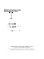
The operating principle of the vacuum servo is
best illustrated by the following calculation:
Example (Fig. 11.45(a)) A direct acting vacuum
servo booster has a 200 mm diameter power piston
suspended on both sides by the induction manifold
vacuum (depression), amounting to a gauge reading
of 456 mm Hg, that is 0.6 bar below atmospheric
pressure.
(Note 1 bar 760 mm Hg 100 KN/m
2
).
The foot pedal leverage ratio is 4:1 and the mas-
ter cylinder has 18 mm diameter.
Determine the following when a pedal effort of
300 N is applied and the rear power piston chamber
which was occupied with manifold vacuum is now
replaced by atmospheric air (Fig. 11.45(a)).
a) The push rod thrust and generated primary and
secondary hydraulic brake line pressures due
only to the foot pedal effort.
b) The power push rod thrust and the generated
fluid pressures in the pipe lines due only to the
vacuum servo action.
c) The total pedal push rod and power piston
thrust and the corresponding generated fluid
pressure in the pipe lines when both foot pedal
and servo action are simultaneously applied to
the master cylinder.
Let F foot pedal effort (N)
F
1
pedal push rod thrust (N)
F
2
power piston thrust (N)
P
1
pressure in the rear chamber
(kN/m
2
)
P
2
manifold pressure (kN/m
2
)
P
3
fluid generated pressure (kN/m
2
)
A
1
cross-sectional area of power
piston (m
2
)
A
2
cross-sectional area of master
cylinder bore (m
2
)
a) Pedal push rod thrust F
1
F Â 4
300 Â 4
1200 N or 1:2kN
Master cylinder fluid
pressure P
3
F
1
A
2
1:2
4
(0:018)
2
4715:7kN=m
2
or
47:2 bar
Fig. 11.45 (a and b) Operating principle and characteristics of a vacuum servo
495
b) Power piston thrust F
2
A
1
(P
1
À P
2
)
4
(0:2)
2
(100 À40)
1:88 kN
Master cylinder fluid
pressure P
3
F
2
A
2
1:88
4
(0:018)
2
7387:93 kN=m
2
or
73:9 bar
c) Total power piston and F
1
F
2
pedal push rod thrust
1:2 1:88
3:08 kN
Total master cylinder
fluid pressure P
3
F
3
A
2
3:08
4
(0:018)
2
12103:635 kN=m
2
or 121:04 bar
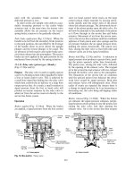
11.8.2 Direct acting suspended vacuum-assisted
brake servo unit (Fig. 11.46(a, b and c))
Brake pedal effort can be reduced by increasing the
leverage ratio of the pedal and master cylinder to
wheel cylinder piston sizes, but this is at the expense
of lengthening the brake pedal travel, which unfor-
tunately extends the brake application time. The
vacuum servo booster provides assistance to the
brake pedal effort, enabling the ratio of master
cylinder to wheel cylinder piston areas to be
reduced. Consequently, the brake pedal push rod
effective stroke can be reduced in conjunction with
a reduction in input foot effort for a given rate of
vehicle deceleration.
Operation
Brakes off (Fig. 11.46(a)) With the foot pedal
fully released, the large return spring in the vacuum
chamber forces the rolling diaphragm and power
piston towards and against the air/vac chamber
stepped steel pressing.
When the engine is running, the vacuum or nega-
tive pressure (below atmospheric pressure) from
the induction manifold draws the non-return
valve away from its seat, thereby subjecting the
whole vacuum chamber to a similar negative pres-
sure to that existing in the manifold.
When the brake pedal is fully released, the outer
spring surrounding the push rod pulls it and the
relay piston back against the valve retaining plate.
The inlet valve formed on the end of the relay
piston closes against the vac/air diaphragm face
and at the same time pushes the vac/air diaphragm
away from the vacuum valve. Negative pressure
from the vacuum chamber therefore passes
through the inclined passage in the power piston
around the seat of the open vacuum valve where it
then occupies the existing space formed in the air/
vac chamber to the rear of the rolling diaphragm.
Hence with the air valve closed and the vacuum
valve open, both sides of the power piston are
suspended in vacuum.
Brakes applied (Fig. 11.46(b)) When the foot
pedal is depressed the pedal push rod moves
towards the diaphragm power piston, pushing the
relay piston hard against the valve retaining plate.
Initially the vac/air diaphragm closes against the
vacuum valve's seat and with further inward push
rod movement the relay piston inlet seat separates
from the vac/air diaphragm face. The air/vac
chamber is now cut off from the vacuum supply
and atmospheric air is now free to pass through the
air filter, situated between the relay piston inlet
valve seat and diaphragm face, to replace the
vacuum in the air/vac chamber. The difference in
pressure between the low primary vacuum chamber
and the high pressure air/vac chamber causes the
power piston and power push rod to move forward
against the master cylinder piston so the fluid pres-
sure is generated in both brake circuits to actuate
the front and rear brakes.
Brake held on (Fig. 11.46(c)) Holding the brake
pedal depressed momentarily continues to move
the power piston with the valve body forward
under the influence of the greater air pressure in
the air/vac chamber, until the rubber reaction pad
is compressed by the shoulder of the power piston
against the opposing reaction of the power push
rod. As a result of squeezing the outer rubber rim
of the reaction pad, the rubber distorts and
extrudes towards the centre and backwards in the
relay piston's bore. Subsequently, only the power
piston and valve body move forward whilst the
relay piston and pedal push rod remain approxi-
mately in the same position until the air valve seat
closes against the vac/air diaphragm face. More
496
Fig. 11.46 (a and b) Vacuum-assisted brake servo unit
497
atmospheric air cannot now enter the air chamber
so that there is no further increase in servo power
assistance. In other words, the brakes are on hold.
The reaction pad action therefore provides a
progressive servo assistance in relation to the foot
pedal effort which would not be possible if only a
simple reaction spring were positioned between the
reaction piston and the relay piston.
If a greater brake pedal effort is applied for a
given hold position, then the relay piston will again
move forward and compress the centre region of
the reaction pad to open the air valve. The extra air
permitted to enter the air/vac chamber therefore
will further raise the servo assistance proportion-
ally. The cycle of increasing or decreasing the
degree of braking provides new states of hold
which are progressive and correspond to the man-
ual input effort.
Brakes released (Fig. 11.46(a)) Releasing the
brake pedal allows the pedal push rod and relay
piston to move outwards; first closing the air valve
and secondly opening the vacuum valve. The exist-
ing air in the air/vac chamber will then be extracted
to the vacuum chamber via the open vacuum valve,
the power piston's inclined passage, and finally it is
withdrawn to the induction manifold. As in the
brakes `off' position, both sides of the power piston
are suspended in vacuum, thus preparing the servo
unit for the next brake application.
Vacuum servo operating characteristics (Fig. 11.45(b))
The benefits of vacuum servo assistance are best
shown in the input to output characteristic graphs
(Fig. 11.45(b)). Here it can be seen that the output
master cylinder line pressure increases directly in
proportion to the pedal push rod effort for manual
(unassisted) brake application. Similarly, with
vacuum servo assistance the output line pressure
rises, but at a much higher rate. Eventually the
servo output reaches its maximum. Thereafter any
further output pressure increase is obtained purely
by direct manual pedal effort at a reduced rate. The
extra boost provided by the vacuum servo in pro-
portion to the input pedal effort may range from
1:1 to 3:1 for direct acting type servos incorpo-
rated on cars and vans.
Servo assistance only begins after a small reac-
tion force applied by the foot pedal closes the
vacuum valve and opens the air inlet valve. This
phase where the servo assistance deviates from the
manual output is known as the crack point.
11.8.3 Types of vacuum pumps
(Fig. 11.47(a, b and c))
For diesel engines which develop very little mani-
fold depression, a separate vacuum pump driven
from the engine is necessary to operate the brake
servo. Vacuum pumps may be classified as recipro-
cating diaphragm or piston or rotary vane types.
In general, for high speed operation the vane
type vacuum pump is preferred and for medium
speeds the piston type pump is more durable than
the diaphragm vacuum pump.
These pumps are capable of operating at depres-
sions of up to 0.9 bar below atmospheric pressure.
One major drawback is that they are continuously
working and cannot normally be offloaded by
interrupting the drive or by opening the vacuum
chamber to the atmosphere.
Reciprocating diaphragm or piston type vacuum
pump (Fig. 11.47(a and b)) These pumps operate
very similarly to petrol and diesel engine fuel lift
pumps.
When the camshaft rotates, the diaphragm or
piston is displaced up and down, causing air to be
drawn through the inlet valve on the downstroke
and the same air to be pushed out on the upward
stroke through the discharge valve.
Consequently, a depression is created within the
enlarging diaphragm or piston chamber causing
the brake servo chamber to become exhausted
(drawn out) of air, thereby providing a pressure
difference between the two sides of the brake
servo which produces the servo power.
Lubrication is essential for plungers and pistons
but the diaphragm is designed to operate dry.
Rotary vane type vacuum pump (rotary exhauster)
(Fig. 11.47(c)) When the rotor revolves, the cell
spaces formed between the drum blades on the inlet
port side of the casing increase and the spaces
between the blades on the discharge port side
decrease, because of the eccentric mounting of the
rotor drum in its casing.
As a result, a depression is created in the enlar-
ging cell spaces on the inlet side, causing air to be
exhausted (drawn out) directly from the brake
vacuum servo chamber or from a separate vacuum
reservoir. However on the discharge side the cells
are reducing in volume so that a positive pressure is
produced.
The drive shaft drum and vanes require lubricat-
ing at pressure or by gravity or suction from the
498
engine oil supply. Therefore, the discharge port
returns the oil-contaminated air discharge back to
the engine crank case.
11.8.4 Hydraulic servo assisted steering and
brake system
Introduction to hydraulic servo assistance (Fig. 11.48)
The alternative use of hydraulic servo assistance is
particularly suited where emission control devices
to the engine and certain types of petrol injection
system reduce the available intake manifold
vacuum, which is essential for the effective opera-
tion of vacuum servo assisted brakes. Likewise,
diesel engines, which produce very little intake
manifold vacuum, require a separate vacuum
source such as a vacuum pump (exhauster) to oper-
ate a vacuum servo unit; therefore, if power assis-
tant steering is to be incorporated it becomes
economical to utilize the same hydraulic pump
(instead of a vacuum pump) to energize both the
steering and brake servo units.
The hydraulic servo unit converts supplied fluid
energy into mechanical work by imposing force
Fig. 11.47 (a±c) Types of vacuum pumps
499
and movement to a power piston. A vane type
pump provides the pressure energy source for
both the power assisted steering and for the brake
servo. When the brake accumulator is being chan-
ged approximately 10% of the total pump output is
used, the remaining 90% of the output returns to
the power steering system. When the accumulator
is fully charged, 100% of the pump output returns
via the power steering control unit to the reservoir.
Much higher operating pressures are used in a
hydraulic servo compared to the vacuum type
servo. Therefore the time needed to actuate the
brakes is shorter.
The proportion of assistance provided to the
pedal effort is determined by the cross-sectional
area ratio of both the power piston and reaction
piston. The larger the power piston is relative to the
reaction piston, the greater the assistance will be
and vice versa.
In the event of pump failure the hydraulic accu-
mulator reserves will still provide a substantial
number of power assisted braking operations.
Fig. 11.48 Hydraulic servo-assisted and brake system (ATE)
500
Pressure accumulator with flow regulator and cut-
out valve unit (Fig. 11.49(a and b)) The accumu-
lator provides a reserve of fluid under pressure if
the engine should stall or in the event of a failure of
the source of pressure. This enables several brake
applications to be made to bring the vehicle safely
to a standstill.
The pressure accumulator consists of a spherical
container divided in two halves by a rubber dia-
phragm. The upper half, representing the spring
media, is pressurized to 36 bar with nitrogen gas
and the lower half is filled with the operating fluid
under a pressure of between 36 and 57 bar. When
the accumulator is charged with fluid, the dia-
phragm is pushed back, causing the volume of the
nitrogen gas to be reduced and its pressure to rise.
When fluid is discharged, the compressed nitrogen
gas expands to compensate for these changes and
the flexible diaphragm takes up a different position
of equilibrium. At all times both gas and fluid
pressures are similar and therefore the diaphragm
is in a state of equilibrium.
Accumulator being charged (Fig. 11.49(a)) When
the accumulator pressure drops to 36 bar, the cut-
out spring tension lifts the cut-out plunger against
the reduced fluid pressure. Immediately the cut-out
ball valve opens and moves from its lower seat to its
uppermost position. Fluid from the vane type pump
now flows through the cut-out valve, opens the
non-return conical valve and permits fluid to pass
through to the brake servo unit and to the under side
of the accumulator where it starts to compress the
nitrogen gas. The store of fluid energy will therefore
increase. At the same time, the majority of fluid
from the vane type pump flows to the power assisted
steering control valve by way of the flutes machined
in the flow regulator piston.
Accumulator fully charged (Fig. 11.49(b)) When the
accumulator pressure reaches its maximum 57 bar,
the cut-out valve ball closes due to the fluid pres-
sure pushing down the cut-out plunger. At the
same time, pressurized fluid in the passage between
the non-return valve and the rear of the flow reg-
ulating piston is able to return to the reservoir via
the clearance between the cut-out plunger and
guide bore. The non-return valve closes and the
fluid pressure behind the flow regulating piston
drops. Consequently the fluid supplied from the
pump can now force the flow regulator piston
further back against the spring so that the total
fluid flow passes unrestricted to the power assisted
steering control valve.
Hydraulic servo unit (Fig. 11.50(a, b and c)) The
hydraulic servo unit consists of a power piston
which provides the hydraulic thrust to the master
cylinder. A reaction piston interprets the response
from the brake pedal input effort and a control
tube valve, which actuates the pressurized fluid
delivery and release for the servo action.
Brakes released (Fig. 11.50(a)) When the brake
pedal is released, the push rod reaction piston and
control tube are drawn towards the rear, firstly
causing the radial supply holes in the control tube
to close and secondly opening the return flow hole
situated at the end of the control tube. The pres-
surized fluid in the operating chamber escapes
along the centre of the control tube out to the low
pressure chamber via the return flow hole, where it
then returns to the fluid reservoir (container). The
power piston return spring pushes the power piston
back until it reaches the shouldered end stop in the
cylinder.
Brakes normally applied (Fig. 11.50(b)) When the
brake pedal is depressed, the reaction piston and
control tube move inwards, causing the return flow
hole to close and partially opening the control tube
supply holes. Pressurized fluid from either the accu-
mulator or, when its pressure is low, from the pump,
enters the control tube central passage and passes
out into the operating chamber. The pressure build-
up in the operating chamber forces the power piston
to move away from the back end of the cylinder.
This movement continues as long as the control tube
is being pushed forwards (Fig. 11.50(b)).
Holding the brake pedal in one position prevents
the control tube moving further forwards. Conse-
quently the pressure build-up in the operating
chamber pushes the power piston out until the
radial supply holes in both the power piston and
control tube are completely misaligned. Closing the
radial supply holes therefore produces a state of
balance between the operating chamber fluid thrust
and the pressure generated in the tandem master
cylinder.
The pressure in the operating chamber is applied
against both the power piston and the reaction
piston so that a reaction is created opposing the
pedal effort in proportion to the amount of power
assistance needed at one instance.
501
Fig. 11.49 (a and b) Flow regulator with pressure accumulator
502
Braking beyond the cut-out point (Fig. 11.50(c))
When the accumulator cut-out pressure is reached,
the control tube touches the power piston, causing
the radial supply holes in the control tube to fully
align with the power piston. Under these condi-
tions, the accumulator is able to transfer its max-
imum pressure to the operating chamber. The
power piston is therefore delivering its greatest
assistance. Any further increase in master cylinder
output line pressure is provided by the brake pedal
effort alone, as shown in Fig. 11.51, at the minimum
and maximum cut-out pressures of 36 and 57 bar
respectively.
Rear brake circuit pressure regulator and cut-out
device (Fig. 11.52(a, b and c)) The rear brake
pressure regulator and cut-off device provide an
increasing front to rear line pressure ratio, once
the line pressing in the rear pipe line has reached
some predetermined minimum value. In other
words, the pressure rise in both front and rear pipe
lines increases equally up to some pre-set value, but
beyond this point, the rear brake pipe line pressure
increases at a much reduced rate relative to the
front brakes. An additional feature is that if the
front brake circuits should develop some fault, then
automatically the pressure regulator is bypassed to
ensure that full master cylinder fluid pressure is
able to operate the rear brakes.
Low brake fluid pressure (Fig. 11.52(a)) When the
brakes are lightly applied, the pressure in the front
pipe line circuit pushes the cut-off piston over
against the opposing spring force. Simultaneously,
fluid from the master cylinder enters the inlet port,
passes through the open pressure reducing valve,
then flows around the wasted cut-off piston on its
way out to the rear brake pipe line circuit.
Fig. 11.50 (a±c) Hydraulic servo unit
503
High braking fluid pressure (Fig. 11.52(b)) With
increased foot pedal effort, the fluid pressure enter-
ing the inlet port and passing through the pressure
reducing valve, on the way to the rear brake circuit
outlet port, rises proportionally. Eventually the
resultant force imposed on the stepped piston,
caused by the fluid pressure acting on the large
and small surface areas of the piston, pushes it
outwards against the resistance of the preload
spring until the pressure reducing valve closes.
Further master cylinder generated pressure acting
on the annular face of the stepped piston forces the
piston to move in the opposite direction, thereby
increasing the rear brake pipe line fluid pressure on
the large surface area side of the piston, but at
a reduced rate to that of the master cylinder output
fluid pressure. The pressure reducing valve is
immediately dislodged from its seat. The pressure
reducing valve opens and closes repeatedly with
rising master cylinder output fluid pressure until
the reduced pressure on the large surface area out-
put side of the piston has adjusted itself. These
pressure characteristics are shown in Fig. 11.52(d).
Front brake circuit fail condition (Fig. 11.52(c)) If
the front brake circuit should fail, the pressure
imposed on the cut-off piston collapses, enabling
the spring at the opposite end to push over the cut-
off piston so that the left hand side of the shuttle
valve opens and the right hand side closes. The
pressure reducing valve passage to the rear brake
line is immediately cut off and the direct passage
via the left hand shuttle valve is opened. Pressure
from the master cylinder is therefore transmitted
unrestricted directly to the rear brake pipe line. The
effect of failure in the front brake circuit will be
a considerable increase in foot pedal movement.
11.9 Pneumatic operated disc brakes (for trucks
and trailers)
Heavy duty disc brake arrangements normally use
a floating-caliper design which does not resort to
hydraulic actuation, but instead relies on com-
pressed air to supply the power source via a dia-
phragm operated air chamber actuator. The disc
brake unit consists of a rotating disc attached to the
road-wheel hub and a floating caliper supported
on the caliper carrier which is itself bolted to the
stub-axle or casing.
11.9.1 Floating caliper with integral half
eccentric lever arm (Fig. 11.53(a and b))
When the brakes are applied air pressure pushes
the actuator chamber diaphragm to the left hand
side and so tilts the actuator lever about the two half
needle roller bearing pivots (Fig. 11.53(a and b)).
This results in the eccentric (off-set) bearing pin
pushing the right hand friction pad towards the
right hand side of the disc via the bridge block,
see Fig.11.53(b). Simultaneously as the right hand
friction pad bears against the right hand side of the
disc, a reaction force now acts on the caliper and is
transferred to the opposite friction pad so that both
pads squeeze the disc with equal force. Thus the
caliper in effect floats; this therefore centralizes the
friction pads so that both pads apply equal pres-
sure against their respective faces of the disc. The
brake torque produced depends upon the air pres-
sure relayed to the brake actuator chamber, the
effective diaphragm area of the chamber and the
leverage ratio created by the lever arm `R' and
eccentric off-set `r', i.e. R/r. When the brakes are
released the pull-off spring pushes the bridge block
assembly back to the off position, thus producing
a running clearance between the pads and disc,
see Fig. 11.53(a).
Floating caliper with eccentric shaft and lever
(Fig. 11.54(a)) With this type of heavy duty com-
mercial vehicle disc brake a floating caliper is used
in conjunction with an eccentric and lever to clamp
the pads against the friction faces of the disc. The
eccentric part of the eccentric shaft is surrounded
Fig. 11.51 Hydraulic servo action pressure
characteristics
504
by needle rollers positioned inside a bored hole in
the bridge block and is connected to the inside pad
via two threaded adjustment barrels and a load
plate. On either side of the eccentric are stub
shafts which are mounted via needle rollers in
the caliper.
When the brakes are released the lever arm
takes up a position in which the lobe side of
the eccentric leans slightly to the right hand side
of the vertical (Fig. 11.54(c)). As the brake is
applied (Fig. 11.54(b)) the lever arm and eccentric
swivels so that the lobe moves to the vertical
position or just beyond, hence the bridge block
will have moved to the right hand side (towards
the disc face) by x x
2
À x
1
where x equals pad
take-up clearance. Thus when the brakes are
applied compressed air is released into the actuator
chamber; this pushes the diaphragm and push rod to
the left hand side, causing the lever arm to rotate
anticlockwise. As a result the eccentric lobe forces
Fig. 11.52 (a±d) Rear brake circuit pressure regulator and cut-off device
505
(a) brake released
Force
Reaction
force
(b) brake applied
r
R
Actuator air chamber
Lever arm
Half eccentric
Bearing pin
Bridge block
Pull-off spring
Pad (right hand)
Ventilated disc
Pad (left hand)
Caliper
Fig. 11.53 (a and b) Pneumatic operated disc brake ± floating caliper with integral half eccentric lever arm
506
(b) Brake applied (c) Brake released
Bridge
block
Caliper
Pads
Vented disc
Load plate
Slide pin
Threaded
adjustment
post
Gear
plate
segment
Bevel
gear
Bridge
block
Threaded
adjustment
barrel
Override
clutch
Adjuster
gear
train
cassette
Actuator
air chamber
Lever
arm
Eccentric
shaft
Needle
rollers
(a) Plan
view
Force
Shaft
and
eccentric
Caliper
carrier
x
2
x
1
x = x – x
12
where
x = pad take-up
Fig. 11.54 (a±c) Pneumatic operated disc brake ± eccentric shaft and lever with gear driven automatic adjustment
mechanism
507
Sleeve fork
& barrel rotated
while brake is
applied
Sleeve fork
in the brake
released position
(b) Brake applied (c) Brake released
Force
Sleeve
fork
Strike
pins
Half
eccentric
Override
clutch
Drive
spindle
Sleeve
fork
Chain
sprocket
wheel
Fork
prongs
Adjuster
chain
Bearing pin
Pull-off
spring
Needle
rollers
Sprocket
wheel &
spindle
Half eccentric
and lever arm
Threaded
adjustment
barrel
Bridge block
Slide pin & sleeve
Pads
Ventilated disc
Caliper carrier
(a) Plan view
Strike pins
Load plate
Bearing
pin
Needle
rollers
Fig. 11.55 (a±c) Pneumatic operated disc brake ± half eccentric shaft and lever with gear driven automatic adjustment
mechanism
508
the bridge block and consequently the inner pad
towards the right hand face of the disc. Conversely
a reaction force acting though the eccentric stub
shaft and caliper pulls the whole caliper, and subse-
quently the outer pad, towards the left hand face of
the disc until the desired amount of friction force is
generated between the pads and disc to either slow
down or park the vehicle.
Automatic pad clearance gear-driven type adjuster
mechanism (Fig. 11.54(a, b and c)) A constant
running clearance between the pad and disc is main-
tained with this mechanism; this device operates by
the to and fro movement of the lever arm about the
eccentric stub shafts every time the brakes are
applied and released (Fig. 11.54(a)). Drawing
together of the brake pads is achieved by partial
rotation of the eccentric lobe within the bridge
block, thus movement is transmitted to the pads
via the two threaded adjustment barrels which are
screwed either side of the eccentric onto the
threaded adjuster posts which are rigidly attached
to the inner brake pad load plate.
A gear-plate segment is attached to one side of
the eccentric via a slot and tongue. The segment
teeth mesh with a bevel gear which houses the over-
ride clutch (one-way clutch operating between
balls rolling up and down inclined plains), see Fig.
11.54(a). Any partial rotation of the eccentric is
transferred to the threaded adjustment barrels via
the override clutch and the train of gears.
Thus every time the brake lever arm moves from
the released to the applied position, the threaded
adjustment barrels are partially screwed out from
the threaded adjustment posts, thereby causing the
load plate and pad to move further towards the
inside face of the disc. Conversely each time the lever
arm moves from the applied to the released pos-
ition, the override one-way clutch disengages, so
preventing the threaded adjustment barrels being
screwed in again. Eventually after many braking
applications, the threaded adjustment barrels will
have screwed out the threaded adjustment posts
sufficiently to cause the inner pad to touch the
inner face of the disc.
Eventually after many braking applications, the
threaded adjustment barrels will have screwed the
threaded adjustment posts sufficiently out to cause
the inner pad to touch the inner face of the disc. At
this point, the slight tightening between the male
and female threads generates sufficient friction in
the screw threads and underneath the flange head
of the threaded adjustment barrels to cause the
override clutch to slip, hence further rotation of
the threaded adjustment barrels ceases. As pad
and disc wear occurs, the threaded adjustment bar-
rels once again commence to turn; a constant run-
ning clearance is thus maintained during service.
Automatic pad clearance chain-driven type adjuster
(Fig. 11.55(a, b and c)) This mechanism main-
tains a constant running clearance between the
pads and disc; the adjuster is operated by the rock-
ing movement of the lever arm each time the brakes
are applied and released (Fig. 11.55(a and b)). Brak-
ing force is transferred from the lever arm (Fig.
11.55(a)) to the brake pad via the bridge block and
the two threaded adjustment barrels which are
screwed on either side of the lever arm into the
bridge block; the shouldered blind ends of the
threaded barrels fit into recesses formed in the
load plate. On one side of the lever arm (Fig.
11.55(a, b and c)) are two fork pins which mesh
with three prongs formed on the fork sleeve; this
sleeve slides over a drive spindle situated inside one
of the threaded adjustment barrels. An override
clutch is formed at the opposite end to the pronged
teeth of the fork sleeve (Fig. 11.55(a)), this consists
of a race of balls rolling on ramps (inclined plains)
formed by the ball-guide grooves.
Every time the brakes are applied the lever arm
tilts causing the meshing strike pins to twist the
fork sleeve clockwise and then back to its original
position when the brakes are released (Fig. 11.55
(b and c)). Thus the clockwise movement of the
sleeve is relayed to the threaded adjustment barrel
via the override clutch, but the fork sleeve anti-
clockwise return movement of the override clutch
releases the threaded adjustment barrel, thus the
threaded barrel is progressively screwed towards
the disc thereby taking up the running clearance
caused by pad and disc wear. The running clear-
ance is maintained by the slackness between the
strike pin and prong teeth. Even take-up of the
running clearance is obtained via the chain
sprocket wheels and chain (Fig. 11.55(a)) which
transfers the same rotary motion to the second
threaded adjustment barrel. Any over-adjustment
will cause the override clutch to slip. The sum clear-
ance of both sides of the disc, that is, the total run-
ning clearance, should be within 0.6 and 0.9 mm.
A larger clearance will cause a take-up clearance
time delay whereas a very small clearance may lead
to overheating of the discs and pads.
509
12 Air operated power brake equipment and vehicle
retarders
12.1 Introduction to air powered brakes
As the size and weight of road vehicles increase
there comes a time when not only are manual
brakes inadequate, but there is no point in having
power assistance because the amount of braking
contributed by the driver's foot is insignificant
relative to the principal source of power, be it
vacuum or hydraulic energy, and therefore power
operated brakes become essential. A further con-
sideration is that the majority of heavy commercial
or public service vehicles are propelled by diesel
engines which do not have a natural source of
vacuum and therefore require a vacuum pump
(exhauster) driven from the engine to supply the
vacuum energy. However, if a separate pump has
to be incorporated to provide the necessary power
transmitting media, a third energy source with def-
inite advantages and few disadvantages can be
used; that is compressed air.
Reciprocating compressors driven off the engine
can operate efficiently and trouble-free at pressures
in the region of 7±8 bar, whereas vacuum assisted
brakes can only work at the most with depressions
of 0.9 bar below atmospheric pressure. Conse-
quently compressed air has a power factor advan-
tage of between 7 and 8 times that for an equivalent
vacuum source when used as a force transmitting
media.
Conversely, hydraulic pumps are compelled to
work at pressures of between 50 and 60 bar. The
pressures generated in the pipe lines may reach
values of 100 bar or even more. Consequently,
because of these high pressures, small diameter
servo cylinders and small bore pipes are utilized.
This may appear to merit the use of hydraulic
energy but, because of the very high working pres-
sure in a hydraulic operated brake system, much
more care has to be taken to avoid fluid leakage
caused by wear or damage. Compressed air as a
power transmitting media would operate at pres-
sures of only one-tenth of an equivalent hydraulic
source, but for large vehicles where there is more
space, there is no real problem as much larger
diameter cylinders can be used. In addition, if
there is a leakage fault in a hydraulic layout it
will eventually drain the supply fluid so that the
brakes cannot continue to function, whereas small
leakages of air in an air power operated braking
system will not prevent the brakes operating even if
this does take place at slightly reduced stopping
efficiency.
12.2 Air operated power brake systems
12.2.1 Truck air over hydraulic brake system
(Fig. 12.1)
Compressed air supply Air is drawn into the com-
pressor and then discharged into and out of the wet
tank where it is semi-dried; it then flows to the
multi-circuit protection valve, here it divides to
feed the two service reservoirs. At the same time,
pressurized air from the reservoirs combine
through internal passages in the multi-circuit pro-
tection valve to supply the remote spring brake
actuator via the hand control valve.
Service line circuit (Fig. 12.1) There are two ser-
vice lines feeding into a tandem power cylinder
controlled by a dual foot valve, so that if a fault
develops in one service line the air supply to the
other circuit will not be interrupted. The air pres-
sure is then converted to hydraulic pressure by the
power piston push rod pushing the tandem master
cylinder hydraulic piston forward. The hydraulic
fluid supply is split into two circuits feeding the
front and rear brake expander cylinders. To bal-
ance the proportion of braking provided by the
rear axle according to the load carried, a hydraulic
load sensing valve is installed on the tandem master
cylinder rear axle output circuit. This therefore
modifies the fluid pressure reaching the rear brake
cylinders.
Secondary line circuit (Fig. 12.1) With the dual air
and hydraulic lines, both systems operate independ-
ently and therefore provide a safeguard against
failure of one or the other circuit. Thus the
hand control valve is used only to park the vehicle.
510
Moving the hand valve lever from `off' to `park'
position exhausts air from the remote spring actu-
ator chamber. This permits the power spring within
the actuator to expand and exert its full pull to the
mechanical parking brake rod linkage.
12.2.2 Tractor three line brake system (Fig. 12.2)
Compressed air supply (Fig. 12.2) The compressor
in this arrangement is controlled by a separate
unloader valve. An alcohol evaporator is installed
in the air intake, so that in cold weather alcohol can
be introduced into the airstream to lower the freez-
ing point of any water which may be present. When
the compressor is running light, a check valve built
into the evaporator prevents alcohol entering the
air intake. Pressurized air from the compressor is
then delivered to both the service and secondary
park reservoirs via the check valves on the inlet side
of each reservoir.
Service line circuit (Fig. 12.2) When the foot
pedal is depressed, air from the service reservoir is
permitted to flow directly to the tractor's front and
rear service line chambers in each of the double
diaphragm actuators which are mounted on the
tractor axles. At the same time, a pressure signal
is passed to the relay valve piston. This opens the
valve so that the service storage line pressure flows
from the service reservoir to the service line coup-
ling (yellow) via the pressure protection valve. The
pressure protection valve in the service storage
(emergency) line and the relay valve in the service
line safeguard the tractor's air supply, should a
large air leak develop in the flexible tractor to
trailer coupling hose or if any other fault causes
a loss of air pressure.
Secondary line circuit (Fig. 12.2) Applying the
hand control valve lever delivers a controlled air
pressure from the secondary park reservoir to the
front wheel secondary chambers, which form part
of the double diaphragm actuators, and to the
secondary line (red) coupling, which then delivers
pressurized air to the trailer brakes via a flexible
hose. Note that there is no secondary braking to
Fig. 12.1 Truck air over hydraulic system
511