Bearing Design in Machinery Episode 2 Part 7 pps
Bạn đang xem bản rút gọn của tài liệu. Xem và tải ngay bản đầy đủ của tài liệu tại đây (268.06 KB, 17 trang )
alumina oxide, silicon carbide, and silicon nitride decreased with increasing
sliding velocities. The minimum friction coefficient of silicon carbide and silicon
nitride is as low as 0.01 in the presence of water.
Experiments were conducted in oil-lubricated ceramic journal bearings.
The experiments showed lower friction coefficient for silicon nitride journals (in
comparison to steel journals) for bearings made of tin-coated Al-Si alloy, forged
steel, and cast aluminium matrix composite with silicon carbide reinforcement
(cast MMC). All bearings were lubricated with SAE 10W-30 oil (Wang et al.,
1994).
11.5.2.3.1 Silicon Carbide and Silicon Nitride
As discussed earlier, these are the best-performing high-temperature, high-
strength ceramics. They have high-temperature-oxidation resistance and the
highest strength in structures. Silicon nitride has higher strength than silicon
carbide up to 2600
F, but above this temperature silicon carbide is stronger.
Silicon carbide and silicon nitride are inert to most chemicals, and for most
applications they exhibit similar corrosion resistance. An important design
consideration is that they have the lowest thermal expansion coefficient in
comparison to other ceramics. In addition, they have the lowest density. They
also have the highest compressive strengths. Silicon nitride is the only ceramic
material used as a roller bearing material (see Chap. 13).
Ceramic journal bearings are widely used in very corrosive environments
where metals cannot be used. For example, sealed pumps driven by magnetic
induction are used for pumping corrosive chemicals. Most sealed pumps operate
with ceramic sleeve bearings of silicon carbide. The ceramic sleeves are used
because of their corrosion resistance and for their nonmagnetic properties.
However, the use of a silicon carbide sleeve in a sliding bearing was not
successful in all cases. These bearings operate with the process fluid as lubricant.
These fluids, such as gas and water often have low viscosity. These bearings
perform well as hydrodynamic bearings with a full fluid film only at the high
rated speeds. During starting and stopping there is direct contact of the journal
with the ceramic sleeve. The silicon carbide sleeve is brittle and suffers severe
wear from a direct contact; it does not have long life in pumps that operate with
frequent start-ups. In such cases, all-ceramic rolling bearings made of silicon
nitride proved to be a better selection. The silicone nitride rolling bearings are not
so sensitive to frequent start-ups and show good corrosion resistance to
chemicals.
11.5.2.3.2 Alumina Oxide
Alumina oxide has a high maximum useful temperature and good compressive
strength. It was the first ceramic to be investigated as an advanced bearing
material. Currently, it is being researched and developed as a candidate for plain
Copyright 2003 by Marcel Dekker, Inc. All Rights Reserved.
bearings. It is also currently used in certain plain bearings. It was reported that in
the presence of lubricant it has a low coefficient of friction similar to PTFE.
However, for the sliding of dry ceramics, the coefficient of friction is higher than
that of compatible metals (Ogawa and Aoyama, 1991).
11.5.2.3.3 Zirconia
Zirconia has the highest friction coefficient and wear rates relative to other
ceramics. Zirconia’s wear rate increased dramatically with increasing sliding
velocity. Zirconia has the lowest operating temperature and the lowest modulus of
elasticity and a very high hardness.
Researchers have been trying to modify the Zirconia manufacturing process
in order to increase its compressive strength and temperature range by reducing
its grain size. Zirconia was considered a good candidate for roller-element
bearings because it has relatively low modulus of elasticity. Low-modulus
elasticity allows ceramics to flake like metals when failing as rolling elements.
Silicon nitride is the only other ceramic that flakes. The others fail catastrophi-
cally.
11.5.2.3.4 Ruby Sapphire
Ruby sapphire has the highest hardness and maximum useful temperature. It is
being investigated for use in plain and rolling bearings. It is the engineering
ceramic with the least reported data.
11.5.3 Other Nonmetallic Beari ng Materials
11.5.3.1 Cemented Carbide
This generally consists of tungsten carbide (97%) and Co (3.0%). It can withstand
extreme loading and high speeds. It must have good alignment and good
lubrication. This material is used in high-speed precision grinders.
11.5.3.2 Rubber
Rubber bearings are used mostly on propeller shafts and rudders of ships, in
hydraulic turbines, and in other industrial equipment that processes water or
slurries. The compliance of the rubber helps to isolate vibration, provide quiet
operation, and compensate for misalignment (see Chapt. 9).
11.5.3.3 Wood
Wood bearings have been replaced by plastic and rubber bearings. The main
advantage of wood bearings are their clean operation, low cost, and self-
lubrication properties. Common wood materials are rock maple and oak.
Copyright 2003 by Marcel Dekker, Inc. All Rights Reserved.
11.5.3.4 Carbon Graphite
Carbon graphite has good self-lubricating properties. Carbon graphite bearings
are stable over a wide range of temperatures and are resilient to chemical attack.
In some cases, metal or metal alloys are added to the carbon graphite composition
to improve such properties as compressive strength and density. Carbon graphite
has poor embeddability; therefore, filtered and clean lubricants should be used.
Usually, carbon graphite does not require lubrication. In most cases, it is used in
textile and food-handling machinery.
11.5.3.5 Molybdenum Disul¢de (MoS
2
)
Molybdenum disulfide is similar to graphite in appearance, and it has very low
friction coefficient. In many applications it is mixed with a binder, such as a
thermosetting plastic, in order to ensure retention of the lubricant on the surface.
It has a satisfactory wear life.
11.5.3.6 Po1ymer^Metal Combination
Other types of bearings in the plastic family are the polymer–metal combination.
These are very well known and considered quite valuable as far as bearing
materials are concerned. One variety is made of a porous bronze film layer coated
with a Teflon-lead mixture, plus an all-steel backing. This configuration results in
favorable conductive heat transfer as well as low-friction properties. Industry
reports application of temperatures up to 530
F, which indicate this bearing is
desirable. This bearing material is used in bushings, thrust washers, and flat strips
for handling rotating, oscillating, sliding, radial, and thrust loads. Acetal
copolymer is being applied in small gears that need structural strength, while
still providing low friction and wear.
Problems
11-1 List the plastic bearing materials according to the following:
a. Increasing PV value
b. Increasing allowed temperature
11-2 White metal (babbitt) is currently used as very thin layer. Give an
example of two applications where it would be beneficial to have a
thicker white metal.
11-3 What materials are used in car engine bearings? Explain the reasons
for the current selection.
11-4 Select a bearing material for a low-cost mass-produced food mixer.
Explain your selection.
Copyright 2003 by Marcel Dekker, Inc. All Rights Reserved.
11-5 Summarize the characteristics of nylon 6 that are significant for the
selection of a bearing material. Give three examples of machines
where bearings of nylon 6 can be used and three examples where
this material would not be appropriate.
Copyright 2003 by Marcel Dekker, Inc. All Rights Reserved.
12
Rolling-Element Bearings
12.1 INTRODUCTION
Rolling-element bearings, or, in short, rolling bearings, are commonly used in
machinery for a wide range of applications. In the past, rolling bearings were
referred to as antifriction bearings, since they have much lower friction in
comparison to sliding bearings. Many types of rolling-element bearings are
available in a variety of designs that can be applied for most arrangements in
machinery for supporting radial and thrust loads. The rolling elements can be
balls, cylindrical rollers, spherical rollers, and conical rollers.
12.1.1 Advantages of Rolling-Element Bearings
One important advantage of rolling-element bearings is their low friction. It is
well known that the rolling motion has lower friction in comparison to that of
sliding. In addition to friction, the rolling action causes much less wear in
comparison to sliding. For most applications, rolling-element bearings require
less maintenance than hydrodynamic bearings. To minimize maintenance cost in
certain cases, prepacked rolling-element bearings are available with grease that is
permanently sealed inside the bearing. Ultrahigh-precision rolling bearings are
available for precision machinery, such as precision machine tools and measuring
equipment. It is possible to completely eliminate the clearance and even to
prestress the bearings. This results in a higher stiffness of the bearings, and the
shaft centerline is held tightly in its concentric position. Prestressing the bearings
Copyright 2003 by Marcel Dekker, Inc. All Rights Reserved.
would minimize vibrations as well as reduce any undesired radial displacement of
the shaft.
12.1.2 Fatigue Life
A major limitation of rolling-element bearings is that they are subjected to very
high alternating stresses at the rolling contacts. High-speed rotation involves a
large number of stress cycles per unit of time, which leads to a limited fatigue life.
In fact, prestressing and centrifugal forces at high-speed operation significantly
increase the contact stresses and further reduce the fatigue life.
12.1.3 Terminology
A standard rolling-element bearing has two rings, an outer ring and inner ring,
which enclose the rolling elements, such as balls, cylindrical rollers, and tapered
rollers. The rolling areas on the rings are referred to as raceways. An example is a
deep-groove ball bearing, which has concave raceways (an outer ring raceway
and an inner ring raceway) that form the rolling areas. A cage holds the rolling
elements at equal distance from one another and prevents undesired contact and
rubbing friction among them. The terminology of bearing parts is shown in Fig.
12-1 for various bearing types. This terminology has been adopted by the Anti-
Friction Bearing Manufacturers Association (AFBMA).
12.1.4 Rolling Contact Stresses
There is a theoretical point or line contact between the rolling elements and races.
But due to elastic deformation, the contact areas are actually of elliptical or
rectangular shape. In machinery that involves severe shocks and vibrations, the
contact stresses can be very high.
In the United States, the standard bearing material is SAE 52100 steel
hardened to 60 RC. This steel has a high content of carbon and chromium. It is
manufactured by an induction vacuum melting process, which minimizes porosity
due to gas released during the casting process.
Stainless steel AISI 440C hardened to 58 RC is the standard rolling bearing
material for corrosive environments. The allowed limit of rolling contact stress for
SAE 52100 is 4.2 GPa (609,000 psi). For rolling bearings made of AISI 440C
stainless steel, the allowed limit of compression stress is only 3.5 GPa
(508,000 psi). Discussion of other rolling bearing materials and manufacturing
processes is included at the end of Chapter 13.
The theory of elasticity indicates that the maximum shear stress of rolling
contact is below the surface. Due to repeated cyclic stresses, scaly particles
eventually separate from the rolling surfaces. Fatigue failure is evident in the form
of metal removal, often referred to as flaking (or spalling), at the rolling contact
surfaces of raceways and rolling elements.
Copyright 2003 by Marcel Dekker, Inc. All Rights Reserved.
research and development, which has resulted in improved materials for high-
speed and heavy-duty operation.
Due to the rolling action, the rolling elements and races are subjected to
periodic stress cycles that can result in material failure due to fatigue. The fatigue
life of rolling bearings is statistically distributed. The data for these statistics must
be obtained only by many experiments for each bearing type over a long period of
time. Fatigue life depends on the material and its processing methods, such as
heat treatment. Fatigue life is also a function of the magnitude of the maximum
stress and temperature at the contacts between the raceways and the rolling
elements during operation. If stresses are low, fatigue life can be practically
unlimited.
The stresses in dry contacts can be calculated via the theory of elasticity
(Hertz equations). In addition to fatigue, the high stresses result in considerable
wear. However, the surfaces are usually lubricated, and under favorable conditions
there is a very thin lubrication film at very high pressure that separates the rolling
surfaces. Whenever this film is thicker than the surface asperities, it would
prevent any direct contact. In this way, this fluid film plays an important role in
reducing wear. The analysis of this film is based on elastohydrodynamic (EHD)
theory. The analysis of the fluid flow and pressure wave inside this thin film is
performed in a similar way to that for hydrodynamic bearings. But in addition,
EHD analysis considers the elastic deformation near the contact area and the
increasing function of viscosity versus pressure.
Recent developments include investigation of the thermal effects in the
EHD film. This analysis is referred to as thermoelastohydrodynamic (TEHD)
analysis. This thermal analysis is quite complex because it solves for the
temperature distribution by considering the dissipation of heat due to viscous
friction, heat transfer, and finally the viscosity dependence on temperature and
pressure distribution. Dedicated computer programs have been developed that
assist in better understanding the phenomena involved in rolling contact.
Although there has been considerable progress in the analysis of stresses
and fluid films, for design purposes the life of the rolling-element bearings must
be estimated by means of empirical equations based on experiment. Due to the
statistical nature of bearing life, bearings are selected to have a very high
probability of operation without failure for a certain reasonable period of the
life of the machine (such as 5 or 10 years). The life-period requirement is usually
determined before the design of a machine is initiated.
Failure due to fatigue is only one possible failure mode among other, more
frequent failure modes, which have a variety of causes. Proper lubrication,
mounting, and maintenance of the bearing can prevent most of them. It is
interesting to note that although most rolling bearings are selected by considering
their fatigue life, only 5–10% of the bearings actually fail by fatigue. The causes
for most bearing failures are misalignment, improper mounting, corrosion,
Copyright 2003 by Marcel Dekker, Inc. All Rights Reserved.
penetration of dust or other hard particles into the bearing and lack of proper
lubrication (oil starvation or not using an appropriate lubricant).
In addition to fatigue and the other reasons just mentioned, overheating can
be a frequent cause of rolling bearing failure. Bearing overheating can be caused
by heat sources outside the bearing, such as in the case of a steam turbine or
aircraft engine. Also, friction-energy losses are converted to heat, which is
dissipated in the bearing. In most cases overheating is due to heavy load and
high speed. Higher bearing temperatures have an adverse effect on the lubricant.
As the temperature increases, the oil oxidation process is accelerated. A rule of
thumb is that the lubrication life is halved for every 10
C increase in temperature.
Thermal analyses as well as measurements have indicated that during
operation there is a temperature gradient inside the bearing. Heat is transferred
better from the outer ring through the housing than from the inner ring. In most
practical cases of moderate load and speed, the outer ring temperature is lower
than that of the inner ring by 5–10
C. This difference in temperature results in
uneven thermal expansion. If the bearing has a small internal clearance or no
clearance, it would result in extra thermal stresses. The thermal stresses are in the
form of a tight fit and higher contact stress between the rolling elements and the
races. During high-speed operation, the additional stresses further increase the
temperature. There is a risk that this sequence of events can result in an unstable
closed-loop process of rising temperature and stress that can lead to failure in the
form of thermal seizure. For this reason, standard rolling-element bearings are
manufactured with sufficient internal clearance to reduce the risk of thermal
seizure.
At high speeds, the centrifugal forces of the rolling elements combine with
the external load and thermal stresses to increase the maximum total contact
stress between a rolling element and the outer ring race. Therefore, a combination
of heavy load and high speed reduces the bearing fatigue life. In extreme cases,
this combination can cause a catastrophic failure in the form of bearing seizure.
The risk of failure is high whenever the product of bearing load and speed is high,
because the amount of heat generated by friction in the bearing is proportional to
this product. In conclusion, the load and speed are two important factors that must
be considered in the selection of the proper bearing type in order to achieve
reliable operation during the expected bearing life.
Developments in aircraft turbine engines resulted in a requirement for
increasing power output at higher shaft speed. As discussed earlier (see Chap. 1),
rolling bearings are used for aircraft engines because of the high risk of an
interruption in the oil supply of hydrodynamic or hydrostatic bearings. At the
very high speed required for gas turbines, the centrifugal force of the rolling
elements is a major factor in limiting the fatigue life of the bearings. The
centrifugal forces of the rotating rolling elements increase the contact stresses at
the outer race and shorten the bearing fatigue life.
Copyright 2003 by Marcel Dekker, Inc. All Rights Reserved.
The contact force on the outer race increases due to the centrifugal force of
a rolling element. The centrifugal force F
c
½N is
F
c
¼ m
r
o
2
c
R
c
ð12-1Þ
Here, m
r
is the mass of the rolling element [kg] and o
c
is the angular speed
[rad=s] of the center of a rolling element in its circular orbit (equivalent to the
cage angular speed, which is lower than the shaft speed). The radius R
c
½m is of
the circular orbit of the rolling-element center. The units indicated are SI, but
other unit systems, such as the Imperial unit system, can be applied. In a deep-
groove bearing, centrifugal force directly increases the contact force on the outer
race. But in an angular contact ball bearing, which is often used in high-speed
turbines, the contact angle results in a higher resultant reaction force on the outer
raceway.
Equation (12-1) indicates that centrifugal force, which is proportional to the
second power of the angular speed, will become more significant in the future in
view of the ever-increasing speeds of gas turbines in aircraft and other applica-
tions. Similarly, bearing size increases the centrifugal force, because rolling
elements of larger bearings have more mass as well as larger-orbit radius.
Therefore, the centrifugal forces are approximately proportional to the second
power of the DN value (rolling bearing bore in millimeters times shaft speed in
RPM). The centrifugal force of the rolling elements is one important considera-
tion for limiting aircraft turbine engines to 2 million DN. A future challenge will
be the development of the technology in order to break through the DN limit of 2
million.
12.1.5 Misalignment
Bearings in machines are subjected to a certain degree of angular misalignment
between the shaft and bearing centerlines. A bearing misalignment can result
from inaccuracy of assembly and machining (within the tolerance limits). Even if
the machining and assembly are very precise, there is a certain misalignment due
to the shaft’s bending under load. Certain bearing types are more sensitive to
angular misalignment than others. For example, cylindrical and tapered roller
bearings are very sensitive to excessive misalignment, which results in uneven
pressure over the roller length.
In applications where there is a relatively large degree of misalignment, the
designer can select a self-aligning roller-element bearing. In most cases, it is more
economical to use a self-aligning bearing than to specify close tolerances that
involve the high cost of precision manufacturing. Self-aligning bearings allow
angular errors in machining and assembly and reduce the requirement for very
close tolerances. Self-aligning bearings include self-aligning ball bearings and
spherical roller bearings. The design of a self-aligning bearing is such that the
Copyright 2003 by Marcel Dekker, Inc. All Rights Reserved.
shape of the cross section of the outer raceway is circular, which allows the
rolling elements to have an angular degree of freedom and self-alignment
between the inner and outer rings.
12.2 CLASSIFICATION OF ROLLING-ELEMENT
BEARINGS
Ball bearings can operate at higher speed in comparison to roller bearings
because they have lower friction. In particular, the balls have less viscous
resistance when rolling through oil or grease. However, ball bearings have
lower load capacity compared with roller bearings because of the high contact
pressure of point contact. There are about 50 types of ball bearings listed in
manufacturer catalogues. Each one has been designed for specific applications
and has its unique characteristics. The following is a description of the most
common types.
12.2.1 Ball Bearings
12.2.1.1 Deep-Groove Ball Bearing
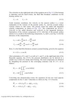
The deep-groove ball bearing (Fig. 12-2) is the most common type, since it can be
used for relatively high radial loads. Deep-groove radial ball bearings are the
most widely used bearings in industry, and their market share is about 80% of
industrial rolling-element bearings. Owing to the deep groove in the raceways,
they can support considerable thrust loads (in the axial direction of the shaft) in
FIG. 12-2 Deep-groove ball bearing.
Copyright 2003 by Marcel Dekker, Inc. All Rights Reserved.
addition to radial loads. A deep-groove bearing can support a thrust load of about
70% of its radial load. The radial and axial load capacity increases with the
bearing size and number of balls.
For maximum load capacity, a filling-notch type of bearing can be used that
has a larger number of balls than the standard bearing. In this design, there is a
notch on one shoulder of the race. The circular notch makes it possible to insert
more balls into the deep groove between the two races. The maximum number of
balls can be inserted if the outer ring is split. However, in that case, external
means must be provided to hold and tighten the two ring halves together.
12.2.1.2 Self-Aligning Ball Bearings
It is very important to compensate for angular machining and assembly errors
between the centerlines of the bearing and the shaft. The elastic deflection of the
shaft is an additional cause of misalignment. In the case of a regular deep-groove
ball bearing, the misalignment causes a bending moment in the bearing and
additional severe contact stresses between the balls and races. However, in the
self-aligning bearing (Fig. 12-3), the spherical shape of the outer race allows an
additional angular degree of freedom (similar to that of a universal joint) that
prevents the transfer of any bending moment to the bearing and prevents any
additional contact stresses.
Self-aligning ball bearings have two rows of balls, and the outer ring has a
common spherical raceway that allows for the self-aligning characteristic. The
FIG. 12-3 Self-aligning ball bearing.
Copyright 2003 by Marcel Dekker, Inc. All Rights Reserved.
inner ring is designed with two restraining ribs (also known as lips), one at each
side of the roller element, for accurately locating the rolling elements’ path on the
inner raceway. But the outside ring has no ribs, in order to allow for self-
alignment. A wide spherical outer race allows for a higher degree of self-
alignment.
Self-aligning ball bearings are widely used in applications where misalign-
ment is expected due to the bending of the shaft, errors in the manufacture of the
shaft, or mounting errors. The design engineer must keep in mind that there are
always tolerances due to manufacturing errors. Self-aligning bearings can be
applied for radial loads combined with moderate thrust loads. The feature that
self-aligning bearings do not exert any bending moment on the shaft is
particularly important in applications that require high precision (low radial
run-out) at high speeds, because shaft bending causes imbalance and vibrations.
The concept of self-alignment is useful in all types of bearings, including sleeve
bearings.
12.2.1.3 Double-Row Deep-Groove Ball Bearing
This bearing type (Fig. 12-4) is used for relatively high radial loads. It is more
sensitive to misalignment errors than the single row and should be used only for
applications where minimal misalignment is expected. Otherwise, a self-align-
ment bearing should be selected.
The design of double-row ball bearings is similar to that of single-row ball
bearings. Since double-row ball bearings are wider and have two rows, they can
FIG. 12-4 Double-row deep-groove ball bearing.
Copyright 2003 by Marcel Dekker, Inc. All Rights Reserved.
carry higher radial loads. Unlike the deep-groove bearing, designs of split rings
(for the maximum number of balls) are not used, and each ring is made from one
piece. However, double-row bearings include groups with larger diameters and a
larger number of balls to further improve the load capacity.
12.2.1.4 Angular Contact Ball Bearing
This bearing type (Fig. 12-5) is used to support radial and thrust loads. Contact
angles of up to 40
(from the radial direction) are available from some bearing
manufacturers, but 15
and 25
are the more standard contact angles. The contact
angle determines the ratio of the thrust to radial load.
Angular contact bearings are widely used for adjustable arrangements,
where they are mounted in pairs against each other and preloaded. In this way,
clearances in the bearings are eliminated or even preload is introduced in the
rolling contacts. This is often done to stiffen the bearings for a rigid support of the
shaft. This is important for reducing the amplitude of shaft vibrations under
oscillating forces. This type of design has significant advantages whenever
precision is required (e.g., in machine tools), and it reduces vibrations due to
imbalance. This is particularly important in high-speed applications. An adjus-
table arrangement is also possible in tapered bearings; however, angular contact
ball bearings have lower friction than do tapered bearings. However, the friction
of angular contact ball bearings is somewhat higher than that of radial ball
bearings. Angular contact ball bearings are the preferred choice in many
important applications, such as high-speed turbines, including jet engines.
FIG. 12-5 Angular contact ball bearing.
Copyright 2003 by Marcel Dekker, Inc. All Rights Reserved.
Single-row angular contact ball bearings can carry considerable radial loads
combined with thrust loads in one direction. Prefabricated mountings of two or
more single-row angular contact ball bearings are widely used for two-directional
thrust loads. Two bearings in series can be used for heavy unidirectional thrust
loads, where two single-row angular contact ball bearings share the thrust load.
Precise axial internal clearance and high-quality surface finish are required to
secure load sharing of the two bearings in series. The bearing arrangement of two
or more angular contact bearings facing the same direction is referred to as
tandem arrangement. The bearings are mounted adjacent to each other to increase
the thrust load carrying capacity.
12.2.2 Roller Bearings
Roller bearings have a theoretical line contact between the unloaded cylindrical
rollers and races. This is in comparison to ball bearings, which have only a
theoretical point contact with the raceways. Under load, there is elastic deforma-
tion, and line contact results in a larger contact area than that of a point contact in
ball bearings. Therefore, roller bearings can support higher radial loads. At the
same time, the friction force and friction-energy losses are higher for a line
contact; therefore, roller bearings are usually not used for high-speed applications.
Roller bearings can be classified into four categories: cylindrical roller
bearings, tapered roller bearings, needle roller bearings and spherical roller
bearings.
12.2.2.1 Cylindrical Roller Bearings
The cylindrical roller bearing (Fig. 12-6) is used in applications where high radial
load is present without any thrust load. Various types of cylindrical roller bearings
are manufactured and applied in machinery. In certain applications where
diameter space is limited, these bearings are mounted directly on the shaft,
which serves as the inner race. For direct mounting, the shaft must be hardened to
high Rockwell hardness, similar to that of the bearing race. For direct mounting,
the radial load must be high in order to prevent slipping between the rollers and
the shaft during the start-up. It is important to keep in mind that cylindrical roller
bearings cannot support considerable thrust loads. Thus, for applications where
both radial and thrust loading are present, it is preferable to use ball bearings.
12.2.2.2 Tapered Roller Bearing
The tapered roller bearing is used in applications where a high thrust load is
present that can be combined with a radial load. The bearing is shown in Fig.
12-7. The races of inner and outer rings have a conical shape, and the rolling
elements between them have a conical shape as well. In order to have a rolling
motion, the contact lines formed by each of the various tapered roller elements
Copyright 2003 by Marcel Dekker, Inc. All Rights Reserved.
the tapered rollers as shown in Fig. 12-7. The ribs also align the rollers between
the races. In addition, the larger rib has an important role in supporting the axial
load. A cage holds the cone and rollers together as one unit, but the cup (outer
ring) can be pulled apart.
A single-row tapered roller bearing can support a thrust load in only one
direction. Two tapered roller bearings are usually mounted in opposition, to allow
for thrust support in both directions (in a similar way to opposing angular contact
ball bearings). Moreover, double or four-row tapered roller bearings are applied in
certain applications to support a high bidirectional thrust load as well as radial
load.
The reaction force on the cup acts in the direction normal to the line of
contact of the rolling elements with the cup race (normal to the cup surface). This
force can be divided into axial and radial load components. The intersection of
the resultant reaction force (which is normal to the cup angle) with the bearing
centerline is referred to as the effective center. The location of the effective center
is useful in bearing load calculations.
For example, when a radial load is applied on the bearing, this produces
both radial and thrust reactions. The thrust force component, which acts in the
direction of the shaft centerline, can separate the cone from the cup by sliding the
shaft in the axial direction through the cone or by the cup’s sliding axially in its
seat. To prevent such undesired axial motion, a single-row tapered bearing should
be mounted with another tapered bearing in the opposite direction. This
arrangement is also very important for adjusting the clearance.
One major advantage of the tapered roller bearing is that it can be applied in
adjustable arrangement where two tapered roller bearings are mounted in
opposite directions (in a similar way to the adjustable arrangement of the angular
contact ball bearing that was discussed earlier). This arrangement allows one to
eliminate undesired clearance and to provide a preload (interference or negative
clearance). Bearing preload increases the bearing stiffness, resulting in reduced
vibrations as well as a lower level of run-out errors in precision machining.
However, the disadvantage of bearing preloading is additional contact stresses
and higher friction. Preload results in lowering the speed limit because the higher
friction causes overheating at high speeds.
The adjustment of bearing clearance can be done during assembly and even
during steady operation of the machine. The advantage of adjustment during
operation is the precise elimination of the clearance after the thermal expansion of
the shaft.
12.2.2.3 Multirow Tapered Roller Bearings
The multirow tapered roller bearing (Fig. 12-8) is manufactured with a prede-
termined adjustment that enables assembly into a machine without any further
adjustment. The multirow arrangement includes spacers and is referred to as a
Copyright 2003 by Marcel Dekker, Inc. All Rights Reserved.
shaft. For a direct mounting, the shaft must be properly hardened to a similar
hardness of a bearing ring.
Two types of needle roller bearings are available. The first type, referred to
as full complement, does not include a cage; the second type has a cage to
separate the needle rollers in order to prevent them from sliding against each
other. The full-complement bearing has more rollers and can support higher
radial load. The second type has a lower number of rollers because it has a cage to
separate the needle rollers to prevent them from rubbing against each other. The
speed of a full-complement bearing is limited because it has higher friction
between the rollers. A full-complement needle bearing may comprise a maximum
number of needle rollers placed between a hardened shaft and a housing bore. An
outer ring may not be required in certain situations, resulting in further saving of
space.
12.2.2.5 Self-Aligning Spherical Roller Bearing
This bearing has barrel-shaped rollers (Fig. 12-10). It is designed for applications
that involve misalignments due to shaft bending under heavy loads and due to
manufacturing tolerances or assembly errors (in a similar way to the self-aligning
ball bearing). The advantage of the spherical roller bearing is its higher load
capacity in comparison to that of a self-aligning ball bearing, but it has higher
frictional losses.
Spherical roller bearings are available as single-row, double-row, and thrust
types. The single-row thrust spherical roller bearing is designed to support only
thrust load, and it is not recommended where radial loads are present. Double-row
FIG. 12-10 (a) Spherical roller bearing, (b) spherical roller thrust bearing.
Copyright 2003 by Marcel Dekker, Inc. All Rights Reserved.
spherical roller bearings are commonly used when radial as well as thrust loads
are present.
The double-row spherical roller bearing has the highest load capacity of all
rolling bearings. This is due to the relatively large radius of contact of the rolling
element. It can resist impact and other dynamic forces. It is used in heavy-duty
applications such as ship shafts, rolling mills, and stone crushers.
12.3 HERTZ CONTACT STRESSES IN ROLLING
BEARINGS
Hertz theory considers the elastic deformation and stress distribution near the
contact of the rolling elements and races. Under load, due to an elastic
deformation, the line or point contact becomes a contact area, This area is very
small, resulting in a very high maximum contact pressure of the order of 1–5 GPa
(1 GPa ¼ 145,040 psi).
The calculations of the maximum contact pressure and deformation at the
contact area of the rolling clement and raceways are according to Hertz’s
equations, which are based on the following assumptions.
1. The materials of the two bodies in contact are homogeneous and
isotropic.
2. The yield point of the material is not exceeded, so plastic deformation
is negligible and only elastic deformation is considered for Hertz’s
theory. Elastic deformation is recoverable after the load is removed.
In fact, assumption 2 is not completely accurate in practice. In heavily loaded
rolling bearings there is a small plastic deformation at the contacts. However,
experiments have verified Hertz’s analysis. The actual stresses do not have any
significant deviation from the values predicted by Hertz’s theory.
3. In the contact area, only normal stresses are transmitted. Shear stresses
due to friction on the surface are not considered in Hertz’s theory.
4. The contact area is flat. The effect of any actual curvature can be
disregarded for the analysis of stress distribution.
Concerning the last assumption, Hertz’s theory is less accurate for bearings with a
small radius of curvature, such as at the contact of a deep-groove ball bearing.
The theory is more accurate for bearings with a large radius of curvature, e.g., at
the contact of the outer ring of a self-aligning ball bearing. However, in all
applications, deviations from the actual stresses are not significant for practical
purposes of bearing design.
The ISO 281 standard refers to the limiting static load, C
0
, of rolling-
element bearings. Manufacturers’ catalogues include this limit for rolling bearing
Copyright 2003 by Marcel Dekker, Inc. All Rights Reserved.