SICK dusthunter SB _ Dòng thiết bị đo bụi nổi tiếng của SICK
Bạn đang xem bản rút gọn của tài liệu. Xem và tải ngay bản đầy đủ của tài liệu tại đây (744.5 KB, 12 trang )
Continuous Measurement of Dust
with Low to Medium Concentrations
Intended Purpose
The DUSTHUNTER SB monitor provides
particulate measurement in industrial
plants for process control and PS-11
compliance.
Models
The DUSTHUNTER SB is available in the
following versions to cover a wide range
of applications:
• DUSTHUNTER SB50
• DUSTHUNTER SB100
The DUSTHUNTER SB consists of the
following components:
• Sender/receiver unit DHSB-T
• Flange with tube
• MCU control unit (with/without
purge air supply)
• External purge air unit (option)
•Connection cable
• Purge air hose for MCU-P control
unit with integrated purge air supply
DATA SHEET
DUSTHUNTER SB
Scattered Light Particulate Monitor
2
DUSTHUNTER SB
|
SICK
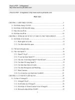
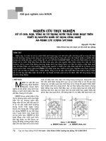
Overview of DUSTHUNTER SB device components
Fig. 1 Layout of the DUSTHUNTER components onsite at the measuring location with internal duct pressure
Fig. 2 Layout of the DUSTHUNTER components onsite at the measuring location with internal duct pressure
Connection cable included
Onsite wiring
MCU-P control unit
(integrated purge air)
Sender/receiver unit
Power supply:
90 250 V AC, 47 63 Hz
Internal duct
pressure
< 0.8 in. H
2
O
(<2 hPa)
(1)
(2)
Optional modules
(I/O, interface)
Purge air hose
DN 1.58 inches (40 mm)
MCU-N control
unit (without
purge air)
Sender/receiver unit
Purge air hose
DN 1.58 in
(40 mm)
Internal duct
pressure:
0.8 12 in. H
2
O
(2 30 hPa)
External
purge air
unit
Power supply:
90 250 V AC, 47 63 Hz
(1)
Optional modules
(I/O, interface)
(2)
No. Signal cable for connection Length Part No. Remark
(1) MCU control unit – sender/
receiver unit (SR)
16.4 ft (5 m)
32.8 ft (10 m)
7042017
7042018
Order separately
No. Purge air hose Length Part No. Remark
(2) Purge air hose DN 1.58 in
(40 mm)
16.4 ft (5 m)
32.8 ft (10 m)
Sold by the
foot/meter
5304683
Included in scope of
delivery of external
purge air unit
Order separately
< 0.8 In. H
2
O
(<2 hPa)
< 12 In. H
2
O
(<30 hPa)
SICK | DUSTHUNTER SB
3
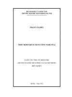
Fig. 3 DUSTHUNTER components onsite at the measuring location with remote MCU < 3,280 ft (1,000 m)
POWER
FAILURE
MAINTENANCE
REQUEST
Status: Measuring
Status
Ack Menu
No. Purge air hose Length Part No. Remark
(3) Purge air hose DN
1.58 in (40 mm)
16.4 ft (5 m)
or
32.8 ft (10 m)
Sold by the
foot/meter 5304683
Included in scope
of delivery of
external purge air
unit
Order separately
No.
Signal cable for
connection
Length Part No. Remark
(1) MCU control unit – sender/
receiver unit (SR)
Onsite
(2) Plug connector for onsite
cable
7045569 Order separately
Sender/receiver unit
(3)
(2)
Max. 3,280 ft
(1,000 m
(1)
MCU-N control
unit (without
purge air)
Power supply:
90 250 V AC, 47 63 Hz
Optional modules
(I/O, interface)
External purge air
unit
Purge air hose
DN 1.58 in (40 mm)
4
DUSTHUNTER SB
|
SICK
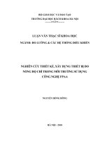
Plug connector for connection to onsite cable
Fig. 4 Pin assignment
For easier opening, insert the plug in the socket on the sender/receiver unit.
Recommendation: For example, cable type UNITRONIC Li2YCYv(TP) 2 x 2 x 0.5 mm
2
with reinforced outer sheath.
Onsite cable
Closed
Closed
Open
Open
A
A
A -A
+24 V
1
2
3
RS485 B
4
RS485 A
5
6
–24 V
7
SICK | DUSTHUNTER SB
5
Mounting suggestion
Fig. 5 Mounting of DUSTHUNTER SB 50/100 with different wall thicknesses
DUSTHUNTER SB 50/100
with measuring angle 7.5
º
DUSTHUNTER SB 50/100
with measuring angle 4.5
º
Measuring
volume
Measuring volume
maximum
11.81 in
(300 mm)
1.18 in
(30 mm)
13.78 in
(350 mm)
15.75 in (400 mm)
25.60 in (650 mm)
27.56 in (700 mm)
31.50 in (800 mm)
70.87 in (1,800 mm)
maximum
25.60 in
(650 mm)
6
DUSTHUNTER SB
|
SICK
Project planning information
Task Requirements Work step
Determine the
measuring and
installation
location
for the device
components
Inlet and outlet paths accor-
ding to local regulations (inlet
at least 5x hydraulic diameter
d
h,
outlet at least 3x d
h
; dis-
tance to stack opening at
least 5x d
h
)
For round and square ducts:
d
h
= duct diameter
Follow specifications for new equipment
Select best possible location for existing
equipment
For too short inlet/outlet paths:
Inlet path > outlet path
For rectangular ducts:
d
h
= 4x cross-section divided
by circumference
• Uniform flow distribution
• Representative dust distri-
bution
Whenever possible, no deflec-
tions, cross-section variations,
feed and drain lines, flaps or
fittings in the area of the inlet
and outlet paths
If conditions cannot be ensured, define
flow profile according to local regula-
tions and select best possible location
Assembly position for the sen-
der/receiver unit
Do not fit vertically on horizon-
tal or slanted ducts;
maximum measuring axis
angle to horizontal 45°
Select best possible location
Accessibility, accident preven-
tion
The device components must
be easily and safely acces-
sible
Provide platforms or pedestals as
required
Installation free of vibrations Acceleration < 1 g Eliminate/reduce vibrations through
suitable measures
Ambient conditions Limit values according to
Technical Data
If necessary:
• Provide weatherproof covers/sun
protection
• Enclose or lag device components
Select the
purge air
supply
Sufficient primary purge air
pressure depending on inter-
nal duct pressure
• Up to +0.8 in. H
2
O
(+2 hPa), control unit with
integrated purge air supply
• Above +0.8 +12 in. H
2
O
(+2 hPa +30 hPa), optio-
nal external purge air unit
Select supply type
Clean intake air Whenever possible, low
amount of dust, no oil, mois-
ture or corrosive gases
Select best possible location for air
intake
Determine required purge air hose
length
Select device
components
Duct wall thickness with isola-
tion
Flange with tube • Select components according to Con-
figuration Tables (see Operating
Instructions);
•If necessary, plan additional measu-
res to fit the flange with tube (see
Operating Instructions)
Internal duct pressure Type of purge air supply
Fitting locations Cable and purge air hose
lengths
Plan
calibration
openings
Access Easy and safe Provide platforms or pedestals as
required
Distances to measuring level No mutual interference bet-
ween calibration probe and
measuring system
Plan sufficient distance between
measuring and calibration level:
approx. 19.69 in (500 mm)
Plan power
supply
Operating voltage,
power requirements
According to Technical Data Plan adequate cable cross-sections and
fuses
SICK | DUSTHUNTER SB
7
Standard connection
Fig. 6 Standard connection DUSTHUNTER SB
Operation/
malfunction
Maintenance
Check
cycle
Limit value
Maintenance
request
Connection cable
(SICK cable or onsite cable)
MCU processor board
Sender/receiver unit
Plug assignment
(View on pin side)
RS485 A
4
RS485 B
3
5
6
-24 V
7
2
1
+24 V
Plug
Socket
White
Green
Yellow
Brown
White
Brown
Green
Yellow
Switching position of the relay
contacts in currentless condition
Relay
12 3 4
5
8
DUSTHUNTER SB
|
SICK
Technical Data DUSTHUNTER SB Scattered Light
Model SB50 SB100
Measuring Parameters
Measured variable Scattered light intensity after gravimetric comparison measurement
Dust concentration output in mg/m³
Measuring range (freely
adjustable)
Minimum Maximum Minimum
Maximum
Dust concentration 0 20 mg/m³ 0 200 mg/m³ 0 10 mg/m³
0 200 mg/m³
1)
Measurement uncertainty ±2% of upper measuring range value
Damping time 1 600 s; freely adjustable
Measuring Conditions
Gas temperature (above dew
point)
–13 1,112°F (–25 600°C)
Sample gas pressure -20 +0.8 in. H
2
O (–50 hPa +2 hPa)
-20 +12 in. H
2
O (–50 hPa +30 hPa)
MCU-P control unit
Optional external purge air unit
Internal duct diameter > 19.7 in (500 mm)
Ambient temperature –40 140°F (–40 +60°C)
–40 113°F (–40 +45°C)
Sender/receiver unit, MCU-N control unit
MCU-P control unit, intake temperature for
purge air
Function Check
Automatic self-test
• Zero
• Reference point test
• Zero value,
• Reference point test
• Contamination correction; contamination
limit values: As from 20% warning, as from
30% malfunction
Manual linearity check Using reference filters
Output Signals
Analog output 0/2/4 20 mA, max. load 750 ; resolution 10 bits; electrically isolated
1 input on DUSTHUNTER SB50, 3 inputs on DUSTHUNTER SB100 (standard),
2)
Relay output 5 potential-free outputs (changeover contacts) for status signals; load 48 V, 1 A
2)
Input Signals
Analog input 2 inputs 0 20 mA (standard); resolution 10 bits;
2)
Digital input 4 inputs to connect potential-free contacts (e.g. for external maintenance switch,
triggering check cycles);
2)
Communication Interfaces
USB 1.1, RS232 (on termi-
nals)
For measured value inquiries and software updates per PC/laptop using the operating
program
RS485 To connect the sender/receiver unit
Bus protocol
•TCP/IP via Ethernet (optional interface module)
• PROFIBUS-DP via RS485 (optional interface module)
• MODBUS ASCII/RTU via RS485
Energy Supply
Control unit Power supply:
Power consumption:
90 250 V AC, 4 63 Hz; opt. 24 V DC ± 2 V
Maximum 15 W without purge air supply
Maximum 70 W with purge air supply
Sender/receiver unit Power supply:
Power consumption:
24 V from control unit
Maximum 4 W
Optional external purge air
unit
(with blower 2BH13)
Power supply:
Rated current:
Motor rating:
200 240 V/345 415 V at 50 Hz;
220 275 V/380 480 V at 60 Hz
2.6 A/Y 1.5 A
0.37 kW at 50 Hz; 0.45 kW at 60 Hz
SICK | DUSTHUNTER SB
9
Weight
Sender/receiver unit 19.8 lb (9 kg)
22 lb (10 kg)
DHSB-T0
DHSB-T1
Control unit 29.8 lb (13.5 kg)
8.2 lb (3.7 kg)
MCU-P
MCU-N
Optional external purge air
unit
30.9 lb (14 kg)
Miscellaneous
Degree of protection IP 66
IP 54
Sender/receiver unit, control unit
Optional external purge air unit
Connection cable length 16.4 ft, 32.8 ft (5 m, 10 m) Other lengths on request
Purge air hose length 16.4 ft, 32.8 ft (5 m, 10 m) Other lengths on request
Laser Degree of protection 2; capacity < 1 mW; wavelength between 640 nm and 660 nm
Purge air feed volume Maximum 20 m³/h
Maximum 63 m³/h
MCU-P control unit
Optional external purge air unit
1)
More on request
2)
Optional: extendable on request (see Operating instructions)
For more information on the DUSTHUNTER series and its components, please
see the following documents:
• Operating Instructions DUSTHUNTER T, Part No. 8012428
• Operating Instructions DUSTHUNTER SF, Part No. 8012424
• Operating Instructions DUSTHUNTER SP, Part No. 8012426
• Operating Instructions DUSTHUNTER SB, Part No. 8012422
• Operating Instructions DUSTHUNTER C, Part No. 8011952
• Data Sheet SLV4 Purge Air Unit, Part No.8008088
10
DUSTHUNTER SB
|
SICK
Dimensions
All measures are specified in inches (mm).
Fig. 7 DUSTHUNTER SB sender/receiver unit
Fig. 8 MCU-P control unit with integrated purge air supply
15.28 (388)
11.89 (302)
4.33 (110)
1
1
.
0
2
(
2
8
0
)
7.87 (200)
> 11.81 (300)
3.94 (100)
8.07 (205)
10.55 (268)
ø 10.43 (265)
ø 6.26 (159)
8.19 (208)
Meas
15.75 (400)
11.81 (300)
8.66 (220)
16.54 (420)
10.24 (260)
Ø 0.32 (8)
17.91 (455)
SICK | DUSTHUNTER SB
11
Fig. 9 MCU-N control unit without purge air supply - inches (mm)
Fig. 10 Mounting flange with tube - inches (mm)
Meas
11.81 (300)
8.27 (210)
6.30 (160)
12.60 (320)
13.39 (340)
4.72 (120)
Ø 7.68 (195)
L
Ø 8.86 (225)
45° 45°
M12
Name Part No.
Flange with tube, Di = 7.80 (198), length 13.78 (350), St37 2046526
Flange with tube, Di = 7.80 (198), length 27.56 (700), St37 2046492
Flange with tube, Di = 7.80 (198), length 13.78 (350), 1.4571 2047288
Flange with tube, Di = 7.80 (198), length 27.56 (700), 1.4571 2047287
L = 13.78 (350), 27.56 (700)
Ø 10.43 (265)
DUSTHUNTER SB DS/2009-12• DIV03/KE • Printed in USA (2009-12) • Subject to modifications
Bild 11 Weatherproof cover for sender/receiver unit - inches (mm)
19.37 (492)
14.37 (365)
14.17 (360)
9.41 (239)
SICK Process Automation Division
United States - Minneapolis, Minnesota | Houston, Texas | 281-436-5100
Canada - Calgary, Alberta | Toronto, Ontario | 905-771-1444
e-mail: | www.sicknorthamerica.com
Fig. 11