Designation: C 472 – 99 - Physical Testing of Gypsum, Gypsum Plasters and Gypsum Concrete1 ppt
Bạn đang xem bản rút gọn của tài liệu. Xem và tải ngay bản đầy đủ của tài liệu tại đây (76.67 KB, 8 trang )
Designation: C 472 – 99
Standard Test Methods for
Physical Testing of Gypsum, Gypsum Plasters and Gypsum
Concrete
1
This standard is issued under the fixed designation C 472; the number immediately following the designation indicates the year of
original adoption or, in the case of revision, the year of last revision. A number in parentheses indicates the year of last reapproval. A
superscript epsilon (e) indicates an editorial change since the last revision or reapproval.
This standard has been approved for use by agencies of the Department of Defense.
1. Scope
1.1 These test methods cover the physical testing of gyp-
sum, gypsum plasters, and gypsum concrete.
1.2 The test methods appear in the following sections:
Sections
Precautions for Physical Tests 4
Reagents and Materials 5
Free Water 6
Fineness 7
Normal Consistency of Gypsum Plaster 8
Normal Consistency of Gypsum Concrete 9
Setting Time 10
Setting Time (Temperature Rise Method) 11
Compressive Strength 12
Density 13
1.3 The values regarded as the standard are either in
inch-pound units or SI (metric). The values stated first shall be
regarded as the standard. Values following in parentheses are
approximate and are provided for information purposes only.
1.4 The text of this standard references notes and footnotes
which provide explanatory material. These notes and footnotes
(excluding those in tables and figures) are not requirements of
the standard.
1.5 This standard does not purport to address all of the
safety concerns, if any, associated with its use. It is the
responsibility of the user of this standard to establish appro-
priate safety and health practices and determine the applica-
bility of regulatory limitations prior to use. For a specific
precautionary statement, see X1.2.1.
2. Referenced Documents
2.1 ASTM Standards:
C 11 Terminology Relating to Gypsum and Related Build-
ing Materials and Systems
2
C 778 Specification for Standard Sand
2
E 11 Specification for Wire-Cloth Sieves for Testing Pur-
poses
3
3. Terminology
3.1 Definitions:
3.1.1 For useful definitions refer to Terminology C 11.
4. Precautions for Physical Tests
4.1 Gypsum products are greatly affected by small amounts
of impurities introduced by careless laboratory manipulation.
In order to obtain accurate results, it is absolutely essential to
observe the following precautions:
4.1.1 Keep all apparatus thoroughly clean. Remove all
traces of set plaster.
NOTE 1—For mixing pastes and mortars, a 500-ml rubber dental bowl
is a convenience.
N
OTE 2—Use care when drying gypsum, gypsum plasters, or gypsum
concrete. Exceeding the specified drying temperatures may calcine the
specimens, which will cause inaccurate test results.
5. Reagents and Materials
5.1 Distilled or Deionized Water—free of chlorides and
sulfates at a temperature of 21 61°C (70 62°F).
5.2 Standard Sand— Specification C 778, 20–30 sand.
6. Free Water
6.1 Significance and Use—This test method determines the
free water contained in gypsum, gypsum plasters, and gypsum
concrete samples, and prepares the sample for subsequent
testing.
6.2 Apparatus:
6.2.1 Balance, capable of weighing not less than 500 g at
a precision of 0.1 g.
6.2.2 Drying Oven, set at 45 6 3°C.
6.2.3 Desiccator, containing calcium chloride or equiva-
lent desiccant.
6.3 Procedure:
6.3.1 Weigh a sample of not less than 500 g of the material
as received to the nearest 0.1 g and spread it to a thin layer in
a suitable-vessel. Place in an oven (6.2.2) and dry for 2 h; then
cool in a desiccator (6.2.3) and weigh again.
1
These test methods are under the jurisdiction of ASTM Committee C-11 on
Gypsum and Related Building Materials and Systems and are the direct responsi-
bility of Subcommittee C11.01 on Specifications and Test Methods for Gypsum
Products.
Current edition approved May 10, 1999. Published June 1999. Originally
published as C 472–61. Last previous edition C 472–98.
2
Annual Book of ASTM Standards, Vol 04.01.
3
Annual Book of ASTM Standards, Vol 14.02.
1
AMERICAN SOCIETY FOR TESTING AND MATERIALS
100 Barr Harbor Dr., West Conshohocken, PA 19428
Reprinted from the Annual Book of ASTM Standards. Copyright ASTM
6.3.2 Retain the dried sample in an airtight container until
used for the fineness test (Section 7).
6.4 Report—Report the loss in weight as a percentage of the
original weight of the sample as received to a precision of
0.1%.
6.5 Precision and Bias—The precision and bias of the free
water test method have not been determined.
7. Fineness
7.1 Significance and Use—This test method covers a pro-
cedure for determining the fineness of gypsum and gypsum
plasters and is used to determine compliance with gypsum and
gypsum plaster specifications. The degree of correlation be-
tween the results of this test method and service performance
has not been determined.
7.2 Apparatus:
7.2.1 Sieves, as required by a particular gypsum or gypsum
plaster specification, in accordance with Specification E 11.
7.2.2 Balance, capable of weighing not less than 1000 g at
a precision of 0.1 g.
7.2.3 Mechanical Sieving Machine
7.3 Procedure:
7.3.1 Determine fineness by sieving a known weight of the
dried sample through sieves of the specified sizes (Note 3 and
Note 4). The size of the sample to be used in determining
fineness depends upon the particle size of the material. If the
material will pass a 6.3-mm (
1
⁄
4
-in.) sieve, a 100-g sample will
be sufficient; if the largest particles are more than 25 mm (1 in.)
in diameter, use not less than a 1000-g sample. With these
limitations the size of sample to be used is left to the discretion
of the operator. Shake the sample through each sieve with as
little abrasion as possible (Note 5). Weigh the amount of
material retained on each sieve and calculate the fineness,
expressed as a percentage of the weight of the original sample.
7.3.2 If a mechanical sieving machine is used, make a series
of tests at one minute intervals, with each type of material and
sieve size combination to be used. When not more than 0.5 g
passes each sieve in a one minute interval, use that time as the
standard sieving time for that test procedure on that machine.
NOTE 3—For suggested method of sieving gypsum through a 45-µm
(No. 325) sieve, see Appendix X1.
N
OTE 4—The sizes of the sieves to be used are given in the specifica-
tions of ASTM covering the particular product in question.
N
OTE 5—When sieving by hand through a 150–µm (No. 100) sieve, use
a lateral motion, and tap the side of the sieve with the palm of the hand.
Continue without brushing until not more than 0.5 g passes through during
1 min of sieving. If the sieve openings become clogged, transfer the
retained material temporarily to another vessel, invert the sieve over a
sheet of paper on the table and tap it sharply against the table. Then
transfer all the retained material back into the sieve and continue sieving.
7.4 Report—Report the percent by weight retained on each
sieve or passing particular sieves in accordance with the
material specification to the nearest full percentage point.
7.5 Precision and Bias—The precision and bias of the
fineness test method have not been determined.
8. Normal Consistency of Gypsum Plaster
8.1 Significance and Use—This test method is used to
determine the volume of water required for mixing gypsum
plaster when performing the setting time and compressive
strength tests.
8.2 Apparatus:
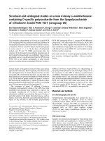
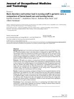
8.2.1 Modified Vicat Apparatus—The modified Vicat appa-
ratus (Fig. 1)
4
shall consist of a bracket, A, bearing a movable
brass rod, B, 6.3 mm in diameter and of suitable length to fit the
Vicat Bracket. A conical plunger made of aluminum with an
apex angle of 53° 08 min and a height of 45 mm shall be
attached to the lower end of the rod. The total weight of the rod
and plunger shall be 35 g.Ameans shall be provided for adding
a weight, G, to the rod, increasing the total weight to 50 g. The
rod shall be capable of being held in any position by a screw,
E. The rod shall have a mark, D, midway between the ends
which moves under a scale, F, graduated in millimetres,
attached to the bracket, A.
8.2.2 Mold—The conical ring mold shall be made of a
noncorroding, nonabsorbent material, and shall have an inside
diameter of 60 mm at the base and 70 mm at the top and a
height of 40 mm.
8.2.3 Base Plate—The base plate for supporting the ring
mold shall be of plate glass and about 100 mm square.
8.2.4 Balance, capable of weighing not less than 500 g at a
precision of 0.1 g.
4
This method is described by Kuntze, R. A., “An Improved Method for the
Normal Consistency of Gypsum Plasters,” ASTM Bulletin No. 246, ASTM, May
1960, p. 35.
A—Hinged support bracket D—Graduation mark
B—Plunger support rod E—Lock screw
C—Conical plunger F—Modified scale
G—Weight
FIG. 1 Modified Vicat Apparatus (Conical Plunger Method)
C 472
2
8.2.5 Graduated Cylinder, shall be made to deliver the
indicated volume at 20°C (68°F) and shall be subdivided to not
less than 1 mL.
8.3 Procedure:
8.3.1 Clean the plunger, mold, and base plate of the modi-
fied Vicat apparatus. Apply a thin coat of petroleum jelly or
other suitable lubricant to the upper surface of the base plate in
order to prevent leaks during the test.
8.3.2 Sift a weighed quantity of the sample (200 to 300 g as
required to fill the mold) into a known volume of water (See
5.1). If the plaster is unretarded, add to the mixing water 0.2 g
of sodium citrate per 100 g of sample. After allowing the
sample to soak for 2 min, stir the mixture for 1 min to an even
fluidity. Pour this sample into the ring mold, work slightly to
remove air bubbles, and then strike off flush with the top of the
mold. Wet the plunger of the modified Vicat apparatus and
lower it to the surface of the sample at approximately the center
of the mold. Read the scale and release the plunger immedi-
ately.After the rod has settled, read the scale again. Make three
determinations on each mix, care being taken to have the mold
completely filled and the plunger clean and wet.
8.3.3 Test gypsum molding plaster and gypsum gauging
plaster with different amounts of water until a penetration of 30
6 2 mm is obtained. Use the rod and plunger for this
determination weighing 35 g.
8.3.4 Test all gypsum mixtures containing aggregates with
different amounts of water until a penetration of 20 6 2mmis
obtained. Add weight to the rod and plunger to bring the total
weight to 50 g for these determinations.
8.3.5 Mix gypsum neat plaster with standard sand (see 5.2)
in the ratio of 200 g of sand to 100 g of plaster before testing
for normal consistency.
8.4 Report:
Report the normal consistency as the average number of
milliliters of water required to be added to 100 g of the dry
mixture to the nearest whole milliliter.
8.5 Precision and Bias—The precision and bias of the test
method for normal consistency of gypsum plaster have not
been determined.
9. Normal Consistency of Gypsum Concrete
9.1 Significance and Use—This test method is used to
determine the volume of water required for mixing gypsum
concrete when performing the setting time and compressive
strength tests.
9.2 Apparatus:
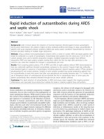
9.2.1 Consistometer (Fig. 2)—The consistometer consists of
a conical vessel made of noncorroding, nonabsorbent material,
and having an inside diameter of 9 in. (229 mm) at the top and
1
3
⁄
4
in. (44.5 mm) at the bottom, and a height of 5
1
⁄
2
in. (139.7
mm). It shall be provided with a sliding gate at the bottom and
supported so that the bottom is 4 in. (102 mm) above the base
plate. The base plate shall be of plate glass, free of scratches
and about 18 in. (457 mm) square.
FIG. 2 Consistometer
C 472
3
9.2.2 Balance, capable of weighing not less than 2000 g at
a precision of 1 g.
9.3 Procedure:
9.3.1 Clean and dry the consistometer and the base plate and
close the sliding gate.
9.3.2 Sift 2000 g of the sample into a known volume of
water (see 5.1) to which 1.0 g of sodium citrate has previously
been added. After allowing the sample to soak for 1 min, stir
the mixture for 3 min to an even fluidity. Pour the mixture into
the consistometer until level with the top. Then rapidly and
completely open the sliding gate, allowing the mixture to run
out onto the base plate. When the sliding gate is opened, take
care to avoid jarring the consistometer.
9.3.3 Measure the resulting patty along its major and minor
axes and determine the average diameter.
9.3.4 Test gypsum concrete with different amounts of water
until a patty dimaeter of 380 6 13 mm (15 6
1
⁄
2
in.) is obtained.
9.4 Report—Report the normal consistency as the number
of milliliters of water to the nearest whole milliliter required to
be added to 100 g of the gypsum concrete.
9.5 Precision and Bias—The precision and bias of the test
method for normal consistency of gypsum concrete have not
been determined.
10. Setting Time
10.1 Significance and Use—This test method is used to
determine the setting time of gypsum plaster and gypsum
concrete, and is used to determine compliance with gypsum
plaster and gypsum concrete specifications. Since variable job
conditions influence the setting time, the degree of correlation
between this test method and service performance has not been
determined.
10.1.1 This test method does not determine the time of
complete hydration of gypsum plaster or gypsum concrete. To
determine the time of complete hydration see Setting Time,
(Temperature Rise Method,) Section 11.
10.2 Apparatus:
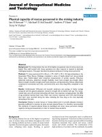
10.2.1 Vicat Apparatus—The Vicat apparatus (Fig. 3) shall
consist of a frame, A, bearing a movable rod, B, weighing 300
g, one end, C, the plunger end, being 10 mm in diameter for a
distance of not less than 50 mm, the other end having a
removable needle, D, 1 mm in diameter and 50 mm in length.
The rod, B, shall be reversible, shall be able to be held in any
position by a screw, E, and shall have an adjustable indicator,
F, that moves over a scale (graduated in millimeters) attached
to the frame, A. The paste shall be held in a rigid conical ring,
G, resting on a glass plate, H, about 100 mm square. The ring
shall be made of a noncorroding, nonabsorbent material and
shall have an inside diameter of 70 mm at the base and 60 mm
at the top, and a height of 40 mm.
10.2.2 In addition, the Vicat apparatus shall conform to the
following requirements:
Weight of plunger 300 6 0.5 g
Diameter of larger end of plunger 10 6 0.05 mm
Diameter of needle 1 6 0.05 mm
Inside diameter of ring at bottom 70 6 3mm
Inside diameter of ring at top 60 6 3mm
Height of ring 40 6 1mm
Graduated scale The graduated scale, when
compared with a standard
scale accurate to within 0.1
mm at all points, shall not
show a deviation at any point
greater than 0.25 mm.
NOTE 6—Automatic setting time apparatus are commercially available
and may be used provided they can be shown to give the same results as
FIG. 3 Vicat Apparatus
C 472
4
the specified apparatus and procedure.
10.2.3 Balance, capable of weighing not less than 500 g at
a precision of 0.1 g.
10.2.4 Stopwatch or Clock, for determining setting time.
10.2.5 Temperature and Humidity Controlled Cabinet, ca-
pable of maintaining a temperature of 21 6 1°C (70 6 2°F)
and a relative humidity of not less than 85 %.
10.3 Procedure:
10.3.1 Gypsum Concrete and All Gypsum Plasters, Except
Gypsum Neat Plaster—Start the timing of the test approxi-
mately at the moment of contact of the dry material with the
water (see 5.1). Mix enough paste to fill the conical ring. For
the quantity of water and directions for mixing, see Section 8,
but do not add retarder. Place the conical ring on the base plate
and fill the ring with the paste level with the top of the ring.
Position the end of the needle so that it just touches the top
surface of the paste and tighten the screw. Release the screw so
that the needle falls freely into the paste. After each penetra-
tion, wipe the needle clean, and move the base plate and ring
slightly so that the needle will not strike the same place twice.
Test the sample at intervals according to the table in 10.3.3.
Setting time is complete when the needle no longer penetrates
to the bottom of the paste. When setting times are expected to
be longer than
1
⁄
2
h, store the test specimens in the cabinet
described in 10.2.5.
10.3.2 Gypsum Neat Plaster—Test gypsum neat plaster for
setting time as mixed with three parts by weight of standard
sand (see 5.2). Mix dry a 100-g sample of the gypsum neat
plaster and 300 g of the sand, and then add sufficient water to
produce a normal consistency. For the quantity of water (see
5.1) and mixing instructions, see Section 8, but do not use
retarder. Stir for 1 min, to an even, lump-free consistency.
Place the mortar in the conical ring and test for setting time as
described in 10.3.1
10.3.3 Frequency of Testing—Test the materials according
to the following schedule:
Kind of Material First Test
Frequency of
Subsequent Tests
Molding plaster 15 min 5 min
Keene’s cement:
Standard 15 min 1 h
Quick set 15 min 5 min
Gypsum concrete 15 min 5 min
Ready mixed plaster 1
1
⁄
2
h1h
Neat plaster 2 h 1 h
Wood-fibered plaster 1
1
⁄
2
h1h
Bond plaster 1
1
⁄
2
h1h
Gauging plaster:
Slow set 40 min 2 h
Quick set 15 min 5 min
10.4 Report—Report the setting time as the elapsed time in
minutes from the time when the sample was first added to the
water to the time when set is complete.
10.5 Precision and Bias—The precision and bias for the
setting time test method have not been determined.
11. Setting Time (Temperature Rise Method)
11.1 Significance and Use:
11.1.1 This test method determines the hydration time by
measuring the maximum temperature rise of gypsum plaster or
gypsum concrete. The temperature rise is caused by the
reaction of calcium sulfate hemihydrate with water to form
calcium sulfate dihydrate. It is assumed that the maximum
temperature rise coincides with the completion of the reaction.
This test method is not used to determine compliance with
specifications for gypsum plaster or gypsum concrete unless it
is specified in the purchase contract.
11.1.2 The setting time determined by this test method is
usually longer than the setting time determined in Section 10.
11.1.3 The degree of correlation between this test method
and service performance has not been determined.
11.2 Apparatus:
11.2.1 Potentiometer—A single- or multiple-channel re-
cording potentiometer or thermistor bridge shall be used to
record the temperature change of the sample under test. The
chart speed shall be not less than 1 in. (25 mm)/h. Imprints
recording the temperature shall not be longer than 1 min apart
for each sample.
11.2.2 Temperature Sensors—Temperature changes shall be
indicated by either thermocouples or thermistors which shall be
movable or in a fixed position. Temperature sensing elements
shall be of such capacity and sensitivity that, when connected
to the recording potentiometer, a temperature change of 0.5°C
(1°F) in the sample shall be recorded on the chart.
11.2.3 Sample Cups—Cups with a capacity of 175 to 275
mL (6 to 9 oz) shall be used. The cup containing the mixture
under test shall be placed inside a matching cup held in an
insulated block or beaker, as specified in 11.2.4. The tempera-
ture sensor, in this case, shall be positioned 25 to 33 % of the
distance up from the bottom and between the inner and outer
cup. Alternately, the cup containing the test mixture shall be
positioned over a spring-loaded sensor to ensure close contact
with the bottom of the cup.
11.2.4 Insulated Block or Beaker, with walls and bottom
having a thermal resistance of not less than R6 (1.1 (m
2
·K)/ W)
(6 (h·ft
2
·°F)/Btu), and a centered cavity into which the sample
cup fits snugly.
NOTE 7—An insulating block may be constructed from a block of
expanded polystyrene. Carve a cavity in the block so that the sample cup
fits snugly, leaving walls and bottom not less than 40 mm (1.5 in.) thick.
An insulating beaker may be made by stuffing glass fiber or mineral wool
insulation not less than 50.8 mm (2 in.) thick around the sample container
and within the walls of a beaker. The insulated block or beaker should
have an insulated cover of the same insulating material through which the
temperature probe can extend into the test material.
11.3 Test Conditions— Perform tests in a room or cabinet
maintained at a temperature of 21 6 1.1°C (70 6 2°F).
Maintain materials and mixing water used for the test at a
temperature of 21 6 1.1°C (70 6 2°F).
NOTE 8—If a constant-temperature cabinet is not available, a constant-
temperature water bath may be fitted with a cover which will admit the
body of the cup holder but not its rim, so that the cup holder is in contact
with the water in the bath.
11.4 Procedure:
11.4.1 Gypsum Concrete and All Gypsum Plasters, Except
Gypsum Neat Plaster—Start the timing of the test at the
moment of contact of the dry material with the water. Mix
approximately 200 g of the sample to make a paste of normal
consistency. Place the paste in a clean dry sample cup to about
20 mm (
3
⁄
4
in.) from the top. Place the filled cup in an empty
C 472
5
cup in the insulated block or beaker and adjust the sensing
element as required in 11.2.3. Cover the cup with a watch glass
or plastic film or cover the surface of the paste with mineral oil
to a depth of approximately 5 mm (
1
⁄
4
in.).
11.4.2 Gypsum Neat Plaster—Prepare the plaster in accor-
dance with 10.3.2 and test in accordance with 11.4.1.
11.5 Report—Report the setting time as the elapsed time in
minutes from the time when the sample was first added to the
water to the time when maximum temperature rise is attained.
11.6 Precision and Bias—The precision and bias for the
setting time, temperature rise method, have not been deter-
mined.
12. Compressive Strength
12.1 Significance and Use—This test method is used to
determine the compressive strength of gypsum plaster and
gypsum concrete and is used to determine compliance with
applicable specifications. The correlation between this test
method and service performance has not been determined.
12.2 Apparatus:
12.2.1 Specimen Molds—Molds for making test specimens
shall be 2-in. (50.8 mm) split cube molds made of noncorrod-
ible material and shall be sufficiently rigid to prevent spreading
during molding. The molds shall have not more than three cube
compartments and shall be separable into not more than two
parts. When assembled, the parts of the molds shall be held
firmly together, and dimensions shall conform to the following
requirements: Interior faces shall be plane surfaces with a
maximum variation of 0.001 in. (0.03 mm) for new molds and
0.002 in. (0.05 mm) for old molds; distance between opposite
faces, and height of the molds, measured separately for each
cube compartment, shall be 2 6 0.005 in. (50.8 6 0.13 mm)
for new molds or 2 6 0.020 in. (50.8 6 0.51 mm) for old
molds, angle between adjacent interior faces and between
interior faces and top and bottom planes of the mold shall be 90
6 0.5°, measured at points slightly removed from the intersec-
tion of the faces.
12.2.2 Testing Machine, either the hydraulic or the screw
type, with sufficient opening between the upper bearing surface
and the lower bearing surface of the machine for the use of
verifying apparatus. The load applied to the test specimen shall
be indicated with an accuracy of 61.0 %. The load indicating
device shall have a means of indicating maximum load. The
upper bearing shall be a spherically seated, hardened metal
block firmly attached at the center of the upper head of the
machine. The center of the sphere shall lie at the center of the
surface of the block in contact with the specimen. The block
shall be free to tilt in any direction. A hardened metal bearing
block shall be used beneath the specimen to minimize wear of
the lower platen of the machine. The lower bearing block shall
have concentric circles at
1
⁄
4
-in. intervals centered on the block
to facilitate accurate centering of the test specimen. The
bearing block surfaces intended for contact with the specimen
shall have a Rockwell hardness number not less than 60 HRC.
These surfaces shall not depart from plane surfaces by more
than 0.0005 in. (0.013 mm) when the blocks are new and 0.001
in. (0.025 mm) after use.
12.2.3 Drying Oven, a mechanical convection oven main-
tained at a temperature of 45 6 3°C and a relative humidity not
more than 50 %.
12.2.4 Desiccator, containing magnesium perchlorate or
calcium chloride that is capable of being tightly sealed and of
such a size as to hold not less than one set of 6 cubes.
12.3 Test Specimens :
12.3.1 Mix sufficient sample at normal consistency to pro-
duce not less than 1000 mL (34 fluid oz) of mixed mortar and
cast into six specimen molds (see 12.2.1). Premix neat gypsum
plaster dry with two parts by weight of standard sand (see 5.2).
For the quality and quantity of water, see 5.1 and Section 8, but
do not add retarder. Place the required amount of water in a
clean 2-L (2-qt) mixing bowl.
12.3.2 For all gypsum plasters except gypsum concrete, add
the required amount of dried plaster and allow to soak for 2
min. Mix vigorously (about 150 complete circular strokes per
minute) for 1 min with a metal spoon, stiff-bladed spatula or
mechanical mixer (see Note 9) to produce a mortar of uniform
consistency. For gypsum concrete, soak for 1 min, and stir
vigorously (about 150 complete circular strokes per minute)
with a large spoon or mechanical mixer for 3 min. Setting time
of the mortar, as determined by Sections 10-10.5, shall be
within the time limits shown in Table 1.
NOTE 9—The Hobart N-50 mixer has been found satisfactory for this
purpose.
12.3.3 If setting times as determined in accordance with
Section 10 are more than the maximum limits shown in Table
1, discard the cubes and adjust the setting time by adding
freshly ground gypsum accelerator to the plaster, or add
molding plaster to Keene’s cement. Do not use more gypsum
accelerator or molding plaster than 1 % of the dry weight of
plaster or Keene’s cement.
12.3.4 Coat the molds with a thin film of mineral oil or other
mold release agent and place on an oiled glass or metal plate.
Place a layer of mortar about 25 mm (1 in.) in depth in each
mold and puddle ten times across the mold between each pair
of opposite faces with a 25 mm (1 in.) wide spatula to remove
air bubbles. Fill the molds to a point slightly above the tops of
the molds, by the same filling and puddling procedure used for
the first layer. Also fill the conical mold for the Vicat apparatus
described in 10.2.1 and 10.2.2 and determine the setting time
(see 10.3). As soon as the mortar or paste has set, cut off the
excess to a plane surface flush with the top of the mold, using
a stiff broad knife or similar implement.
TABLE 1 Setting-Time Limits for Mortar
Kind of Material
Setting Time, min
min max
Molding plaster 20 140
Keene’s cement:
Standard 40 120
Quick set 20 40
Gypsum concrete 20 40
Ready-mixed plaster 90 120
Neat plaster (with 2 parts sand) 120 150
Wood-fibered plaster 90 120
Bond plaster 120 150
Gauging plaster:
Slow set 40 120
Quick set 20 40
Veneer plaster 30 90
C 472
6
12.3.5 Place the filled molds in moist air (90 to 100 %
relative humidity). Remove the cubes from the molds at any
time after they are thoroughly hardened, but retain in the moist
air for not less than a total of 16 h. Place the cubes in an oven
as specified in 12.2.3. Dry until successive weights are identi-
cal to 0.1 g (or differ by no more than 0.1 g). Then place the
cubes in a desiccator as described in 12.2.4 for a minimum of
16 h before testing. Test the cubes immediately on removal
from the desiccator.
12.4 Procedure—As soon as the cube specimens have been
dried (12.3), determine their compressive strengths. (If density
is to be determined, do so at this time. (See Section 13)).
Position the cubes in the testing machine so that the load is
applied on surfaces formed by faces of the molds, not on top
and bottom. Apply the load continuously and without shock, at
a constant rate within the range 15 to 40 psi/s. Do not exceed
40 psi/s ((275 kPa)/s) after 50 % of the maximum load has
been reached.
12.5 Report—Report the average compressive strength as
the compressive strength of the material, in psi (Mpa) rounded
to the nearest whole psi (0.1 Mpa) except that if the strengths
of one or two of the cubes vary more than 15 % from the
average of the six, discard them and report the compressive
strength as the average of the remaining specimens. In case the
compressive strengths of three or more cubes vary more than
15 % from the average, discard the results and repeat the test.
12.6 Precision and Bias—The precision and bias for the
compressive strength test method have not been determined.
13. Density
13.1 Significance and Use—This test method is used to
determine the density of cast gypsum concrete and is used to
determine compliance with the specification for gypsum con-
crete. The correlation between this test method and service
performance has not been determined.
13.2 Apparatus:
13.2.1 Balance, capable of weighing not less than 1500 g to
the nearest gram.
13.3 Procedure—Determine the density of gypsum concrete
by weighing the six cubes to the nearest gram after drying and
cooling, as described in 12.3.4, and before determining the
compressive strength.
13.4 Calculation— Calculate the density by multiplying the
total weight of the six cubes by 0.0794.
13.5 Report—Report the density in pounds per cubic foot to
the nearest 1 lb/ft
3
(10 kg/m
3
).
13.6 Precision and Bias—The precision and bias for the
density test method have not been determined.
14. Keywords
14.1 compressive strength; density; free water; fineness;
gypsum; gypsum concrete; gypsum plasters; normal consis-
tency; setting time
APPENDIX
(Nonmandatory Information)
X1. ALCOHOL WASH METHOD OF SIEVING GYPSUM AND GYPSUM PRODUCTS
X1.1 Scope
X1.1.1 This appendix covers a sieve test for fine gypsum
and gypsum products using an alcohol wash method.
X1.2 Significance and Use
X1.2.1 It is impractical to sieve dry gypsum through a fine
sieve, and water cannot be used as a washing agent without
introducing errors due to hydration or solution. This method is
used when a purchase order specifies fineness through fine
sieves.
X1.3 Apparatus
X1.3.1 Sieves, complying with Specification E 11.
X1.3.2 Mechanical Sieving Machine.
X1.3.3 Vessel, with a diameter not less than 50 mm greater
than the sieves, and a depth not less than 75 mm greater than
the height of the sieves.
X1.3.4 Balance, capable of reading to a precision of 0.01 g.
X1.4 Reagents
X1.4.1 Isoprophyl alcohol, 99%. The alcohol may be reused
after decanting or filtering, provided its strength does not fall
below 95%
X1.4.1.1 Caution—When using isoprophyl alcohol, keep
fire away, provide good ventilation, and avoid excessive
inhalation of vapor.
X1.5 Calibration and Standardization
X1.5.1 See 7.3.2 for method of calibrating a mechanical
sieving machine.
X1.6 Procedure
X1.6.1 Place the alcohol in a vessel (X1.3.3) to a depth of
50 mm more than the height of the sieve. Weigh approximately
50 g of the sample to a precision of 0.01 g and place on a
45-µm or coarser sieve up to and including the 150 µm (No.
100).
X1.6.2 Lower the sieve into the alcohol until the specimen
is wetted throughout. Lift the sieve out of the alcohol, with a
swirling motion, permitting the alcohol to drain through the
specimen back into the vessel. Repeat this operation not less
than eight times, until the alcohol passes freely through the
sieve and the specimen is essentially free from fines. Wash the
residue retained on the sieve with about 100 mL of clear
alcohol, and then blot the bottom of the sieve with a soft, dry,
lint-free cloth. Dry the sieve containing the residue at 45 6
3°C.
C 472
7
X1.6.3 Shake the sieve on a mechanical shaker for 2 min 6
2 s. If desired, to permit simultaneous determinations of
coarser fractions, transfer the residue after drying and before
shaking to a series of coarser sieves up to and including the 150
µm nested in sequential order above the 45-µm sieve. Weigh
the material retained on each sieve to the nearest 0.01 g.
X1.7 Calculation
X1.7.1 Calculate the percent of the original specimen re-
tained on or through each sieve as follows:
% retained 5
~
B/A
!
· 100
% through 5
A–B
A
· 100
where:
A 5 Weight of original specimen, and
B 5 weight of specimen retained on sieve.
X1.8 Report
X1.8.1 Report the percent retained or through each sieve to
the nearest 0.1 percent.
X1.9 Precision and Bias
X1.9.1 The precision and bias of the alcohol wash method
of sieving gypsum and gypsum products has not been deter-
mined.
SUMMARY OF CHANGES
Committee C-11 has identified the location of selected changes to this standard since the last issue (C 473–98)
that may impact the use of this standard:
(1) NOTE was added to Section 10.2.2 to allow the use of
automatic setting time apparatus.
The American Society for Testing and Materials takes no position respecting the validity of any patent rights asserted in connection
with any item mentioned in this standard. Users of this standard are expressly advised that determination of the validity of any such
patent rights, and the risk of infringement of such rights, are entirely their own responsibility.
This standard is subject to revision at any time by the responsible technical committee and must be reviewed every five years and
if not revised, either reapproved or withdrawn. Your comments are invited either for revision of this standard or for additional standards
and should be addressed to ASTM Headquarters. Your comments will receive careful consideration at a meeting of the responsible
technical committee, which you may attend. If you feel that your comments have not received a fair hearing you should make your
views known to the ASTM Committee on Standards, 100 Barr Harbor Drive, West Conshohocken, PA 19428.
C 472
8