UMTS Signaling
Bạn đang xem bản rút gọn của tài liệu. Xem và tải ngay bản đầy đủ của tài liệu tại đây (2.77 MB, 169 trang )
JWBK146-FM JWBK146-Kreher January 10, 2007 8:2
Contents
Preface xiii
Acknowledgments xvii
About the Authors xix
1 UMTS Basics 1
1.1 Standards 2
1.2 Network Architecture 4
1.2.1 GSM 4
1.2.2 UMTS Release 99 5
1.2.3 UMTS Release 4 7
1.2.4 UMTS Release 5 8
1.2.5 HSPA 12
1.2.6 UMTS Release 6 21
1.2.7 UMTS Release 7 and Beyond 24
1.2.8 TD-SCDMA 26
1.3 UMTS Interfaces 28
1.3.1 Iu Interface 28
1.3.2 Iub Interface 29
1.3.3 Iur Interface 29
1.4 UMTS Domain Architecture 31
1.5 UTRAN 31
1.5.1 RNC 33
1.5.2 Node B 35
1.5.3 Area Concept 35
1.5.4 UMTS User Equipment and USIM 36
1.5.5 Mobiles 38
1.5.6 QoS Architecture 39
1.6 UMTS Security 41
1.6.1 Historic Development 41
1.6.2 UMTS Security Architecture 46
1.6.3 Authentication and Key Agreement (AKA) 48
1.6.4 Kasumi/Misty 53
1.6.5 Integrity – Air Interface Integrity Mechanism 55
v
JWBK146-FM JWBK146-Kreher January 10, 2007 8:2
vi Contents
1.6.6 Confidentiality – Encryption (Ciphering) on Uu and Iub 58
1.6.7 UMTS Network Transactions 63
1.7 Radio Interface Basics 63
1.7.1 Duplex Methods 64
1.7.2 Multiple Access Methods 64
1.7.3 UMTS CDMA 65
1.7.4 CDMA Spreading/Channelization 66
1.7.5 Microdiversity – Multipath (FDD and TDD) 67
1.7.6 Microdiversity – Softer Handover (FDD) 67
1.7.7 Macrodiversity – Soft Handover (FDD) 68
1.7.8 UMTS Spreading (FDD and TDD) 68
1.7.9 Scrambling 69
1.7.10 Coding Summary (FDD) 69
1.7.11 Signal to Interference (FDD) 69
1.7.12 Cell Breathing (FDD) 70
1.7.13 UMTS Channels (FDD and TDD) 72
1.7.14 Transport Channels (FDD and TDD) 74
1.7.15 Common Transport Channels (FDD and TDD) 74
1.7.16 Dedicated Transport Channels (FDD and TDD) 75
1.7.17 Initial UE Radio Access (FDD) 76
1.7.18 Power Control (FDD and TDD) 77
1.7.19 UE Random Access (FDD) 79
1.7.20 Power Control in Soft Handover (FDD) 80
1.8 UMTS Network Protocol Architecture 81
1.8.1 Iub – Control Plane 82
1.8.2 Iub – User Plane 83
1.8.3 Iur – User/Control Plane 84
1.8.4 luCS – User/Control Plane 85
1.8.5 IuPS – User/Control Plane 86
1.8.6 E – User/Control Plane 86
1.8.7 Gn – User/Control Plane 87
1.9 SIGTRAN 87
1.10 ATM 89
1.10.1 ATM Cell 90
1.10.2 ATM Layer Architecture 91
1.10.3 ATM Adaption Layer (AAL) 91
1.10.4 AAL2 92
1.10.5 AAL5 92
1.11 User Plane Framing Protocol 93
1.11.1 Frame Architecture 93
1.11.2 FP Control Frame Architecture 94
1.12 Medium Access Protocol (MAC) 95
1.12.1 MAC Architecture 95
1.12.2 MAC Data PDU 96
1.12.3 MAC Header Alternatives 98
JWBK146-FM JWBK146-Kreher January 10, 2007 8:2
Contents vii
1.13 Radio Link Control (RLC) 98
1.13.1 RLC Services 99
1.13.2 RLC Functions 100
1.13.3 RLC Architecture 102
1.13.4 RLC Data PDUs 103
1.13.5 Other RLC PDUs 104
1.14 Service Specific Connection Oriented Protocol (SSCOP) 104
1.14.1 Example SSCOP 105
1.15 Service Specific Coordination Function (SSCF) 106
1.16 Message Transfer Part Level 3 – Broadband (MTP3-B) 106
1.17 Internet Protocol (IP) 107
1.17.1 IPv4 Frame Architecture 108
1.18 Signaling Transport Converter (STC) 108
1.19 Signaling Connection Control Part (SCCP) 109
1.19.1 Example SCCP 110
1.20 Abstract Syntax Notation One (ASN.1) in UMTS 111
1.20.1 ASN.1 BER 111
1.20.2 ASN.1 PER 112
1.21 Radio Resource Control (RRC) 112
1.21.1 RRC States (3GPP 25.331) 113
1.21.2 System Information Blocks (SIBs) 118
1.22 Node B Application Part (NBAP) 124
1.22.1 NBAP Functions 124
1.22.2 NBAP Elementary Procedures (EPs) 125
1.22.3 Example – NBAP 126
1.23 Radio Network Subsystem Application Part (RNSAP) 126
1.23.1 RNSAP Functions 126
1.23.2 Example – RNSAP Procedures 127
1.24 Radio Access Network Application Part (RANAP) 128
1.24.1 RANAP Elementary Procedures (EPs) 129
1.24.2 Example – RANAP Procedure 131
1.25 ATM Adaptation Layer Type 2 – Layer 3 (AAL2L3/ALCAP) 131
1.25.1 AAL2L3 Message Format 131
1.25.2 Example – AAL2L3 Procedure 132
1.26 IU User Plane Protocol 134
1.26.1 Iu UP Transparent Mode 134
1.26.2 Iu UP Support Mode Data Frames 134
1.26.3 Iu UP Support Mode Control Frames 136
1.26.4 Example – Iu UP Support Mode Message Flow 136
1.27 Adaptive Multirate (AMR) Codec 136
1.27.1 AMR IF1 Frame Architecture 138
1.28 Terminal Adaptation Function (TAF) 138
1.29 Radio Link Protocol (RLP) 139
1.30 Packet Data Convergence Protocol (PDCP) 140
1.30.1 PDCP PDU Format 140
JWBK146-FM JWBK146-Kreher January 10, 2007 8:2
viii Contents
1.31 Broadcast/Multicast Control (BMC) 141
1.31.1 BMC Architecture 141
1.32 Circuit-Switched Mobility Management (MM) 141
1.33 Circuit-Switched Call Control (CC) 142
1.34 Example – Mobile Originated Call (Circuit Switched) 143
1.35 Packet-Switched Mobility Management (GMM) 144
1.36 Packet-Switched Session Management (SM) 144
1.37 Example – Activate PDP Context (Packet Switched) 145
2 Short Introduction to Network Monitoring, Troubleshooting, and
Network Optimization 147
2.1 Iub Monitoring 147
2.1.1 IMA 147
2.1.2 Fractional ATM 148
2.1.3 Load Sharing and Addressing on Iub 149
2.1.4 Troubleshooting Iub Monitoring Scenarios 150
2.2 Iu Monitoring 151
2.2.1 Troubleshooting Iu Monitoring 154
2.3 Network Optimization and Network Troubleshooting 155
2.3.1 Cell-related Performance Relevant Data 159
2.3.2 Call-related Performance Relevant Data 164
3 UMTS UTRAN Signaling Procedures 171
3.1 Iub – Node B Setup 172
3.1.1 Overview 172
3.1.2 Message Flow 173
3.2 Iub – IMSI/GPRS Attach Procedure 191
3.2.1 Overview 191
3.2.2 Message Flow 192
3.3 Iub CS – Mobile Originated Call 205
3.3.1 Overview 206
3.3.2 Message Flow 207
3.4 Iub CS – Mobile Terminated Call 217
3.4.1 Overview 217
3.4.2 Message Flow 219
3.5 Iub PS – PDP Context Activation/Deactivation 223
3.5.1 Overview 225
3.5.2 Message Flow 226
3.6 Iub – IMSI/GPRS Detach Procedure 235
3.6.1 Overview 235
3.6.2 Message Flow 236
3.7 RRC Measurement Procedures 239
3.7.1 RRC Measurement Types 239
3.7.2 Cell Categories 239
JWBK146-FM JWBK146-Kreher January 10, 2007 8:2
Contents ix
3.7.3 Measurement Initiation for Intrafrequency Measurement 240
3.7.4 Intrafrequency Measurement Events 241
3.7.5 Intrafrequency Measurement Report 244
3.7.6 Intrafrequency Measurement Modification 245
3.7.7 Measurement Initiation for Interfrequency Measurement 247
3.7.8 Further RRC Measurement Groups 248
3.7.9 Changing Reporting Conditions After Transition to CELL
FAC H 249
3.8 Iub – Physical Channel Reconfiguration (PDPC) 250
3.8.1 Message Flow 251
3.9 Channel Type Switching 259
3.9.1 Overview 259
3.9.2 Message Flow 261
3.10 Iub – Mobile-Originated Call with Soft Handover (Inter-Node B,
Intra-RNC) 272
3.10.1 Overview 272
3.10.2 Message Flow (Figure 3.70) 273
3.11 Iub – Softer Handover 286
3.11.1 Overview 286
3.11.2 Message Flow 287
3.12 Iub Interfrequency Hard Handover FDD 290
3.12.1 Interfrequency Hard Handover Overview 291
3.12.2 FDD Interfrequency Inter-Node B Hard Handover Call Flow 292
3.13 RRC Measurements in Compressed Mode and Typical Call Drop 296
3.13.1 Message Flow 296
3.14 High Speed Downlink Packet Access (HSDPA) 301
3.14.1 HSDPA Cell Setup 302
3.14.2 HSDPA Basic Call 304
3.14.3 Mobility Management and Handover Procedures in HSDPA 310
3.14.4 Troubleshooting HSDPA Calls 318
3.14.5 Proprietary Descriptions of HSDPA Call/Mobility Scenarios 320
3.15 High Speed Uplink Packet Access (HSUPA) 323
3.15.1 HSUPA Cell Setup 324
3.15.2 HSUPA Call Scenarios 325
3.15.3 HSUPA Basic Call 328
3.16 NBAP Measurements 330
3.16.1 NBAP Common Measurements 331
3.16.2 NBAP Dedicated Measurements 334
4 TDD (TD-SCDMA) Iub Signaling Procedures 339
4.1 TD-SCDMA Radio Interface Structure and Radio Resource Allocation 340
4.1.1 TD-SCDMA Mobile Originated Speech Call Setup 343
4.1.2 RRC Measurements in TD-SCDMA Radio Mode 349
4.1.3 Intra-Cell Interfrequency Handover in TD-SCDMA 352
4.1.4 Inter-Cell Interfrequency Handover 353
4.1.5 Multi-Service Call CS/PS with Inter-Node B Handover 356
JWBK146-FM JWBK146-Kreher January 10, 2007 8:2
x Contents
5 Iu and Iur Signaling Procedures 363
5.1 Iub-Iu – Location Update 363
5.1.1 Message Flow 364
5.2 Iub-Iu – Mobile-Originated Call 370
5.2.1 Overview 370
5.2.2 Message Flow 372
5.3 Iub-Iu – Mobile-Terminated Call 378
5.3.1 Overview 378
5.3.2 Message Flow 379
5.4 Iub-Iu – Attach 384
5.4.1 Overview 384
5.4.2 Message Flow 385
5.5 Iub-Iu – PDPC Activation/Deactivation 387
5.5.1 Overview 387
5.5.2 Message Flow 388
5.6 Streaming PS Service and Secondary PDP Context 394
5.6.1 Message Flow 395
5.7 Iub-Iu – Detach 398
5.7.1 Overview 398
5.7.2 Message Flow 399
5.8 Iub-Iur – Soft Handover (Inter-Node B, Inter-RNC) 401
5.8.1 Overview 401
5.8.2 Message Flow 402
5.9 Iub-Iu – RRC Re-Establishment (Inter-Node B, Inter-RNC) 412
5.9.1 Overview 412
5.9.2 Message Flow 414
5.10 SRNS Relocation (UE not Involved) 419
5.10.1 Overview 420
5.10.2 Message Flow 421
5.11 SRNS Relocation (UE Involved) 426
5.11.1 Overview 427
5.11.2 Message Flow 429
5.12 Short Message Service (SMS) in UMTS Networks 437
5.12.1 SMS Network Architecture Overview 437
5.12.2 SMS Protocol Architecture 438
5.12.3 Mobile-Originated Short Message 439
5.12.4 Mobile-Terminated Short Message 446
6 Signaling Procedures in the 3G Core Network 453
6.1 ISUP/BICC Call Setup 453
6.1.1 Address Parameters for ISUP/BICC Messages 454
6.1.2 ISUP Call (Successful) 454
6.1.3 ISUP Call (Unsuccessful) 455
6.1.4 BICC Call Setup on E Interface Including IuCS Signaling 458
6.2 Gn Interface Signaling 462
6.2.1 PDF Context Creation on Gn (GTP-C and GTP-U) 464
JWBK146-FM JWBK146-Kreher January 10, 2007 8:2
Contents xi
6.2.2 GTP-C Location Management 465
6.2.3 GTP-C Mobility Management 465
6.2.4 SGSN Relocation 467
6.2.5 Example GTP 467
6.3 Procedures on the Gs Interface 469
6.3.1 Location Update via Gs 469
6.3.2 Detach Indication via Gs 470
6.3.3 Paging via Gs 470
6.4 Signaling on Interfaces Toward HLR 470
6.4.1 Addressing on MAP Interfaces 472
6.4.2 MAP Architecture 473
6.4.3 MAP Signaling Example 475
6.5 Inter-3G
MSC Handover Procedure 477
6.5.1 Inter-3G MSC Handover Overview 480
6.5.2 Inter-3G MSC Handover Call Flow 482
6.6 Inter-3G-2G-3G MSC Handover Procedure 486
6.6.1 Inter-3G-2G MSC Handover/Relocation Overview (Figure 6.42) 489
6.6.2 Inter-3G-2G MSC Handover Call Flow 490
6.6.3 Inter-3G-2G MSC Handover Messages on E Interface 494
6.6.4 Inter-2G-3G MSC Handover/Relocation Overview 495
6.6.5 Inter-2G-3G MSC Subsequent Handover Messages on the E Interface 500
6.6.6 2G-3G CS Inter-RAT Handover on IuCS and Iub Interface 501
6.6.7 PS Inter-RAT Mobility 506
6.7 Customized Application for Mobile Network Enhanced Logic (CAMEL) 509
6.7.1 IN/CAMEL Network Architecture 510
6.7.2 CAMEL Basic Call State Model 511
6.7.3 Charging Operation Using CAMEL 512
6.7.4 CAMEL Signaling Example for GPRS Charging 513
6.8 IP Multimedia Subsystem (IMS) 517
6.8.1 IMS PDP Context Activation Basics 517
6.8.2 IMS UE-UE Call Basics 518
Glossary 521
Bibliography 537
Index 541
JWBK146-FM JWBK146-Kreher January 10, 2007 8:2
xii
JWBK146-01 JWBK146-Kreher January 9, 2007 22:9
1
UMTS Basics
UMTS is real. In a continuously growing number of countries we can walk in the stores of
mobile network operators or resellers and take UMTS PC cards or even third-generation (3G)
phones home and use them instantly. Every day the number of equipments and their feature
sets gets broader. The “dream” of multimedia on mobile connections, online gaming, video
conferencing, real-time video or even mobile TV becomes reality.
With rapid technical innovation the mobile telecommunication sector has continued to grow
and evolve strongly.
The technologies used to provide wireless voice and data services to subscribers, such
as Time Division Multiple Access (TDMA), Universal Mobile Telecommunications System
(UMTS), and Code Division Multiple Access (CDMA), continue to grow in their complexity.
This complexity imparts a time-consuming hurdle to overcome when moving from 2G to 2.5G
and then to 3G networks.
GSM (Global System for Mobile Communication) is the most widely installed wireless
technology in the world. Some estimates put GSM market share above 80 %. Long dominant
in Europe, GSM has a foothold in Latin America and is expanding its penetration in the North
American market.
One reason for this trend is the emergence of reliable, profitable 2.5G General Packet Radio
Service GPRS elements and services. Adding a 2.5G layer to the existing GSM foundation has
been a cost-effective solution to current barriers while still bringing desired data services to
market. The enhancement to EGPRS (Enhanced GPRS) allows a maximum speed of 384 kbps.
However, now EDGE (EDGE; Enhanced Data Rates for GSM Evolution) is under pressure,
because High Speed Downlink Packet Access (HSDPA; see Section 1.2.3) and its speed of 2
Mbps will take huge parts of the market share once it becomes more widely available.
So, the EGPRS operators will sooner or later switch to 3G UMTS services (Figure 1.1),
the latest of which is UMTS Release 7 (Rel. 7). This transition brings new opportunities and
testing challenges, in terms of both revenue potential and addressing interoperability issues to
ensure QoS (Quality of Service).
With 3G mobile networks, the revolution of mobile communication has begun. 4G and
5G networks will make the network transparent to the user’s applications. In addition to
horizontal handovers (for example between Node Bs), handovers will occur vertically between
UMTS Signaling Second Edition Ralf Kreher and Torsten R¨udebusch
C
2007 Tektronix, Inc.
1
JWBK146-01 JWBK146-Kreher January 9, 2007 22:9
2 UMTS Signaling
G-MSC
EIR
MSC
SGSN
GGSN
RNC
BSC
VLR
HLR
PCU
RNC
AuC
Core Network
Circuit switched
Network
e.g. ISDN
Packet switched
Network
e.g. IP
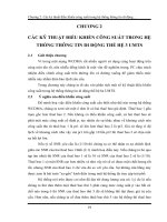
Figure 1.1 Component overview of a UMTS network.
applications, and the UTRAN (UMTS Terrestrial Radio Access Network) will be extended by
a satellite-based RAN (Radio Access Network), ensuring global coverage.
Every day the number of commercial networks in different parts of the world increases.
Therefore, network operators and equipment suppliers are desperate to understand how to
handle and analyze UMTS signaling procedures in order to get the network into operation,
detect errors, and troubleshoot faults.
Those experienced with GSM will recognize many similarities with UMTS, especially in
Non-Access Stratum (NAS) messaging. However, in the lower layers within the UTRAN and
Core Network (CN), UMTS introduces a set of new protocols, which deserve close under-
standing and attention.
The philosophy of UMTS is to separate the user plane from the control plane, the radio
network from the transport network, the access network from the CN, and the Access Stratum
from the Non-Access Stratum.
The first part of this book is a refresher on UMTS basics, and the second part continues with
in-depth message flow scenarios.
1.1 Standards
The ITU (the International Telecommunication Union) solicited several international organi-
zations for descriptions of their ideas for a 3G mobile network:
CWTS China Wireless Telecommunication Standard group
ARIB Association of Radio Industries and Businesses, Japan
T1 Standards Committee T1 Telecommunications, United States
TTA Telecommunications Technology Association, Korea
TTC Telecommunication Technology Committee, Japan
ETSI European Telecommunications Standards Institute
JWBK146-01 JWBK146-Kreher January 9, 2007 22:9
UMTS Basics 3
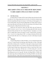
Figure 1.2 IMT-2000.
The ITU decided which standards would be used for “International Mobile Telecommuni-
cations at 2000 MHz.” Many different technologies were combined in IMT-2000 standards
(Figure 1.2).
The main advantage of IMT-2000 is that it specifies international standards and also the
interworking with existing PLMN (Public Land Mobile Network) standards, such as GSM.
In general, the quality of transmission will be improved. The data transfer rate will increase
dramatically. Transfer rates of 384 kbps are already available; 2 Mbps (with HSDPA technol-
ogy) is under test and almost ready to go live in certain parts of Asia. New service offerings
will help UMTS to become financially successful for operators and attractive to users.
The improvement for the users will be the worldwide access available with a cell phone,
and the look and feel of services will be the same wherever the user may be (Figure 1.3).
There is a migration path from 2G to 3G systems that may include an intermediate step, the
so-called 2.5G network. Packet switches –Gateway GPRS Support Node (GGSN) or Serving
GPRS Support Node (SGSN) in the case of a GSM network – are implemented in the existing
CN while the RAN is not changed significantly (Figure 1.4).
Improvement of Quality
Increase of Transfer rates for Data
New Services
General
Simplification of Network Architecture
Standardization of a worldwide System
Increase of potential Market for Vendors
Worldwide Access
Look and feel is everywhere the same
Operator & Vendor
User
Figure 1.3 IMT-2000 standards benefit users, operators, and vendors.
JWBK146-01 JWBK146-Kreher January 9, 2007 22:9
4 UMTS Signaling
UMTS
(WCDMA)
CDMA2000
3x
EDGE
2G
CDMAone
PDC
GSM
TDMA
2.5G
CDMA2000
1x
GPRS
3G
Figure 1.4 Possible migration paths from 2G to 3G.
In the case of a migration from GSM to UMTS a new Radio Access Technology (RAT;
W-CDMA instead of TDMA) is introduced. This means the networks will be equipped with
completely new RANs, which replace the 2G network elements in the RAN. However, EDGE
opens a different way to offer high-speed IP services to GSM subscribers without introducing
W-CDMA.
The existing CDMA cellular networks, which are especially popular in the Americas, will
undergo an evolution to become CDMA2000 networks with larger bandwidth and higher data
transmission rates.
1.2 Network Architecture
UMTS maintains a strict separation between the radio subsystem and the network subsystem,
allowing the network subsystem to be used with other RATs. The CN is adopted from GSM and
consists of two user traffic-dependent domains and several commonly used entities. Traffic-
dependent domains correspond to the GSM or GPRS CNs and handle:
r
circuit-switched-type traffic in the CS domain;
r
packet-switched-type traffic in the PS domain.
Both traffic-dependent domains use the functions of the remaining entities – the Home
Location Register (HLR) together with the Authentication Center (AuC), or the Equipment
Identity Register(EIR) – for subscriber management, mobile station roaming and identification,
and handling different services. Thus the HLR contains GSM, GPRS, and UMTS subscriber
information.
Two domains handle their traffic types at the same time for both the GSM and the UMTS
access networks. The CS domain handles all circuit-switched traffic for the GSM as well as for
the UMTS access network; similarly, the PS domain takes care of all packet-switched traffic
for both the access networks.
1.2.1 GSM
The second generation of PLMN is represented as a Subsystem by a GSM network consisting
of a Network Switching Subsystem (NSS) and a Base Station Subsystem (BSS) (Figure 1.5).
The first evolution step (2.5G) is a GPRS PLMN connected to a GSM PLMN for packet-
oriented transmission.
JWBK146-01 JWBK146-Kreher January 9, 2007 22:9
UMTS Basics 5
BSS
IP
GMSC
MSC
VLR
SGSN
SLR
AuC
HLR
GGSN
Gs
A
Gc
Gr
E
Gn
Gi
PSTN
ISDN
SCP
SMS-SC
STP
D,C
BSC
PCU
BTS
Abis
Gb
E
GPRS PLMN
NSS
Figure 1.5 GSM network architecture. HLR: Home Location Register; SGSN: Serving GPRS Support
Node with Location Register Function; GGSN: Gateway GPRS Support Node; AuC: Authentication
Center; SCP: Service Control Point; SMSC: Short Message Service Center; CSE: CAMEL Service
Entity (Customized Application for Mobile network Enhanced Logic).
The main element in the NSS is the Mobile Switching Center (MSC), which contains the
Visitor Location Register (VLR). The MSC represents the edge toward the BSS and on the other
side as the Gateway MSC (GMSC), the connection point to all external networks, such as the
Public Switched Telephone Network (PSTN) or Integrated Services Digital Network (ISDN).
GSM is a circuit-switched network, which means that there are two different types of physical
links to transport control information (signaling) and traffic data (circuit). The signaling links
are connected to Signaling Transfer Points (STP) for centralized routing whereas circuits are
connected to special switching equipment.
The most important entity in the BSS is the Base Station Controller (BSC), which, along
with the Packet Control Unit (PCU), serves as the interface with the GPRS PLMN. Several
Base Transceiver Stations (BTS) can be connected to the BSC.
1.2.2 UMTS Release 99
Figure 1.6 shows the basic structure of a UMTS Release 99 network. It consists of two different
radio access parts (BSS and UTRAN) and the CN parts for circuit-switched (e.g. voice) and
packet-switched (e.g. email download) applications.
To implement UMTS means to set up a UTRAN, which is connected to a circuit-switched
CN (GSM with MSC/VLR) and to a packet-switched CN (GPRS with SGSN). The interfaces
are named Iu, where IuCS goes to the MSC and IuPS goes to the SGSN. Alternatively, the
JWBK146-01 JWBK146-Kreher January 9, 2007 22:9
6 UMTS Signaling
Core Network CS Domain
Core Network PS DomainUTRAN
BSS
IP
RNC
BSC
PCU
RNC
GMSC
MSC
VLR
SGSN
SLR
HLR
AuC
BTS
Node B
GGSN
Iu-CS
Gs
Iur
Iub
Abis
A
Gc
Gr
E
Gn
Gi
PSTN
ISDN
SCP
SMS-SC
STP
D,C
Gb
Iu-PS
E
Figure 1.6 UMTS Rel. 99 network architecture.
circuit and packet network connections could also be realized with a UMSC (UMTS MSC),
which combines MSC and SGSN functionalities in one network element.
The corresponding edge within UTRAN is the Radio Network Controller (RNC). Other than
in the BSS the RNCs of one UTRAN are connected with each other via the Iur interface.
The base stations in UMTS are called Node B, which is just its working name and has no
other meaning. The interface between Node B and RNC is the Iub interface.
Release 99 (sometimes also named Release 3) specifies the basic requirements to roll out a
3G UMTS RAN. All following releases introduce a number of features that allow operators
to optimize their networks and offer new services. A real network environment in the future
will never be designed strictly following any defined release standard. Rather it must be seen
as a kind of patchwork that is structured following the requirements of network operators and
service providers. So it is possible to introduce, e.g., HSDPA, which is a feature clearly defined
in Rel. 5 in combination with a Rel. 99 RAN.
In addition, it must be kept in mind that owing to changing needs of operators and growing
experience of equipment manufacturers, every three months (four times per year!) all standard
documents of all releases are revised and published with a new version. So development of
Rel. 99 standards is not even finished yet.
It might also be possible that in later standard versions the introduction of features promised
in earlier versions is delayed. This happened, for instance, in the definition of the Home
Subscriber Server (HSS), which was originally introduced in early Rel. 4 standards, but then
delayed to be defined in detail in Rel. 5.
The feature descriptions for higher releases in the following sections are based on documents
not older than the 2004–06 revision.
JWBK146-01 JWBK146-Kreher January 9, 2007 22:9
UMTS Basics 7
Core Network CS Domain
Core Network PS DomainUTRAN
GERAN
IP
RNC
BSC
PCU
RNC
MGW
MGW
BTS
Node B
GGSN
Iu-CS
PSTN
ISDN
SCP
Nb
Nc
Mc
Gs
HLR
AuC
SMS-SC
Server
MSC
Server
Mc
VLR
STP
SGSN
SLR
E
Gr
Gn
Gi
Gb
Gc
Iu-PS
Iu-CS
Iub
Iur
A
Abis
D,C
Figure 1.7 UMTS Rel. 4 network architecture.
1.2.3 UMTS Release 4
3GPP Release 4 introduces some major changes and new features in the CN domains and
the GERAN (GPRS/EDGE Radio Access Network), which replaces GSM BSS (Figure 1.7).
Some of the major changes are:
r
Separation of transport bearer and bearer control in the CS CN.
r
Introduction of new interfaces in the CS CN.
r
ATM (Asynchronous Transfer Mode; AAL2, ATM Adaptation Layer Type 2) or IP (Internet
Protocol) can now be used as the data transport bearer in the CS domain
r
Introduction of low chiprate (also called narrowband) TDD (Time Division Duplex) describes
the RAT behind the Chinese TD-SCDMA standard while UMTS TDD (wideband TDD,
TD-CDMA) is seen as the dominating TDD technology in European and Asian standards
outside China. It is expected that interference in low chiprate TDD has less impact on cell
capacity compared to the same effect in wideband TDD. In addition, low chiprate TDD
equipment will support advanced radio transmission technologies such as “smart antennas”
and beamforming, which allows pointing a single antenna or a set of antennas at the signal
source to reduce interference and improve communication quality.
r
IP-based Gb interface.
r
IPv6 support (optional).
JWBK146-01 JWBK146-Kreher January 9, 2007 22:9
8 UMTS Signaling
The new features and services are (in no specific order):
r
Multimedia services in the CS domain.
r
Handover of real-time applications in the PS domain.
r
UTRAN transport evolutions:
– AAL2 connection QoS optimization over Iub and Iur interfaces;
– Transport bearer modification procedure on Iub, Iur, and Iu interfaces.
r
IP transport of CN protocols.
r
Radio interface improvements:
– UTRA repeater specification;
– DSCH power control improvement.
r
Radio Access Bearer (RAB) QoS negotiation over Iu interface during relocation.
r
RAN improvements:
– Node B synchronization for TDD;
– RAB support enhancement.
r
Transparent end-to-end PS mobile streaming applications.
r
Emergency call enhancements for CS-based calls.
r
Bearer independent CS architecture.
r
Real-time facsimile.
r
Tandem free operation.
r
Transcoder free operation.
r
ODB (Operator Determined Barring) for packet-oriented services.
r
Multimedia Messaging Service.
r
UICC/(U)SIM enhancements and interworking.
r
(U)SIM toolkit enhancements:
– USAT local link;
– UICC Application Programming Interface (API) testing.
– Protocol standardization of a SIM Toolkit Interpreter.
r
Advanced Speech Call Items enhancements.
r
Reliable QoS for PS domain.
The main trend in Rel. 4 is the separation of control and services of CS connections and at
the same time the conversation of the network to be completely IP-based. In CS CN the user
data flow will go through the Media Gateway (MGW), which are elements maintaining the
connection and performing switching functions when required (bearer switching functions of
the MSC are provided by the MGW). The process is controlled by a separate element evolved
from MSC/VLR called the MSC Server (control functions of the MSC are provided by the MSC
Server and also contains the VLR functionality), which, in terms of voice over IP networks,
is a signaling gateway. One MSC Server controls numerous MGWs. To increment control
capacities, a new MSC Server will be added. To increase the switching capacity, MGWs have
to be added.
1.2.4 UMTS Release 5
In 3GPP Release 5, the UMTS evolution continues. The shift to an all IP environment will be
realized: all traffic coming from UTRAN is supposed to be IP-based (Figure 1.8). By changing
GERAN, the BSC will be able to generate IP-based application packets. That is why the
JWBK146-01 JWBK146-Kreher January 9, 2007 22:9
UMTS Basics 9
PS
UTRAN
GERAN
Mc
Cx
Gc
Mw
Mr
CAP
CAP
Mm
Gn
Go
Gi
Gb
A
A
Mc
Gb/
Iu-PS
Iu-CS
Iu-CS
Nc
Nb
CAP
CAP
Cx
Mg
IMS
CS
Applications
& Services
MRF
IP or
ATM
MGW
MSC
Server
CS-GW
S-CSCF
IP
Internet
Intranet
HSS
GGSN
SGSN
PSTN
ISDN
P-CSCF
Applications
& Services
GMSC
Server
SGW
MGW
IP/ATM
IP/ATM
RNC
RNC
Node B
BTS
BSC
Figure 1.8 UMTS Rel. 5 basic architecture.
circuit-switched CN will no longer be part of UMTS Rel. 5. All interfaces will be IP-based
rather than ATM-based.
The databases known from GSM/GPRS will be centralized in an HSS. Together with value-
added services and CAMEL, it represents the Home Environment (HE). CAMEL could perform
the communication with the HE completely. When the network has moved toward IP, the
relationship between circuit- and packet-switched traffic will change. The majority of traffic
will be packet-oriented because some traditionally circuit-switched services, including speech,
will become packet-switched (VoIP). To offer uniform methods of IP application transport,
Rel. 5 will contain an IP Multimedia Subsystem (IMS), which efficiently supports multiple
media components, e.g. video, audio, shared whiteboards, etc.
HSDPA will provide data rates of up to 10 Mbps in downlink direction and lower rates in
uplink (e.g. Internet browsing or video on demand) through the new High Speed Downlink
Shared Channel (HS-DSCH) (for details see 3GPP 25.855).
New in Release 5
r
All network node interfaces connected to IP network.
r
HSS replaces HLR/AuC/EIR.
r
IMS:
– Optional IPv6 implementation;
– Session Initiation Protocol (SIP) for CS signaling and management of IP multimedia ses-
sions;
– SIP supports addressing formats for voice and packet calls and number translation require-
ments for SIP <-> E.164.
JWBK146-01 JWBK146-Kreher January 9, 2007 22:9
10 UMTS Signaling
r
HSDPA integration:
– Data rates of up to 10 Mbps in downlink direction; lower rates in uplink (e.g. Internet
browsing or video on demand);
– New HS-DSCH.
r
All voice traffic is voice over packet.
r
MGW required at Point of Interconnection (POI).
r
SGW (Signaling Gateway; MSC Server) translates signaling to “legacy” (SS7) networks.
r
AMR-WB, an enhanced Adaptive Multirate (Wideband) codec for voice services.
r
New network element MRF (Media Resource Function):
– Part of the Virtual Home Environment (VHE) for portability across network boundaries
and between terminals. Users experience the same personalized features and services in
whatever network and whatever terminal;
– Very similar in function to an MGCF (Media Gateway Control Function) and MGW using
H.248/MEGACO to establish suitable IP or SS7 bearers to support different kinds of media
streams.
r
New network element CSCF (Call Session Control Function):
– Provides session control mechanisms for subscribers accessing services within the IM (IP
Multimedia) CN;
– CSCF is a SIP Server to interact with network databases (e.g. HSS for mobility and AAA
(Authorization, Authentication, and Accounting) for security).
r
New network element SGW:
– In CS domain the user signaling will go through the SGW, which is the gateway for signaling
information to/from the PSTN.
r
New network element CS-GW (Circuit-Switched Gateway):
– The CS-GW is the gateway from the IMS to/from the PSTN (e.g. for VoIP calls).
r
Location services for PS/GPRS.
r
IuFlex:
– Breaking hierarchical mapping of RNCs to SGSNs (MSCs).
r
Wideband AMR (new 16-kHz codec).
r
End-to-end QoS in the PS domain.
r
GTT: Global Text Telephony (service for handicapped users).
r
Messaging and security enhancements.
r
CAMEL Phase 4:
– New functions such as mid call procedures, interaction with optimal routing, etc.
r
Load sharing:
– UTRAN (Radio Network for W-CDMA);
– GERAN (radio network for GSM/EDGE);
– W-CDMA in 1800/1900-MHz frequency spectrums;
– Mobile Execution Environment (MExE) support for Java and WAP applications.
IP Multimedia Subsystem (IMS)
The IMS is a standardized architecture for fixed and mobile multimedia services. It is com-
pletely IP based and uses a 3GPP version of Voice over IP (VoIP) together with SIP. Additionally
it supports all existing phone systems.
JWBK146-01 JWBK146-Kreher January 9, 2007 22:9
UMTS Basics 11
Figure 1.9 Overview of IMS architecture.
The IMS will support all current and future services communication networks. All services
can easily be controlled and charged with this approach. Users can access their services in
their home networks and when roaming.
As the complete IMS is based on IP it really merges cellular networks with all kinds of
internet and multimedia services.
The Proxy-Call State Control Function (P-CSCF) is located together with the GGSN in the
same network. Its main task is to select the I-CSCF in the user’s home network and do some
basic local analysis, e.g. QoS surveillance or number translation.
The Interrogating-CSCF (I-CSCF) provides access to the user’s home network and selects
the S-CSCF (in the home network, too).
The Serving-CSCF (S-CSCF) is responsible for the Session Control, handles SIP requests,
and takes care of all necessary procedures, such as bearer establishment between home and
visited network.
The HSS is the former HLR. It was renamed to emphasize that the database not only contains
location-related, but also subscription-related data (subscribed services and their parameters,
etc.) too (Figure 1.9).
IMS Protocols
r
SIP (Session Initiation Protocol) is a text-based protocol that provides call signaling, regis-
tration, status, control, and security.
r
SDP (Session Description Protocol) is embedded in order to share endpoint media capabil-
ities.
JWBK146-01 JWBK146-Kreher January 9, 2007 22:9
12 UMTS Signaling
r
Diameter is an evolution of RADIUS for Authentication, Authorization, and Accounting.
A peer-to-peer protocol specified as a base protocol and a series of applications.
r
H.248 is a device control protocol that grew out of MGCP. Available as a binary or text
implementation. It instructs MGWs to setup and teardown voice calls and manages media
resources (available circuits and IP ports) and signals endpoint events to the MG (e.g. off-
hook, on-hook).
r
COPS is a protocol used to transmit media-level access control and QoS policy information.
(It is used on the Go interface between the GGSN and the Packet Data Function (PDF).)
r
RTP (Real-time Transport Protocol) and RTCP (Real-Time Control Protocol) provide trans-
port of media streams.
1.2.5 HSPA
A few years ago, UMTS technology was at the early deployment. Now, UMTS is a mainstream
technology, with suitable handsets available in the mid- and low-price range. 3G network oper-
ators are searching for ways to satisfy an increasing number of 3G subscribers and especially to
improve the user’s experience. They have to improve the capacity of 3G networks and support
higher data rates than 384 kbps supported by Rel. 99 UMTS. The solution for these needs were
the enhancements included in 3GPP Rel. 5 known as HSDPA (High Speed Downlink Packet
Access). However, the higher download speed was not enough. With an increasing number
of interactive services the need for improved uplink capacity grew. 3GPP Rel. 6 addressed
that with the standardization HSUPA (High Speed Uplink Packet Access). Both HSDPA and
HSUPA introduce new functions to the radio access network (UTRAN). Node Bs and RNCs
have to be upgraded (Figure 1.11).
HSDPA
A packet-based data service with data speed of up to 1.2–14.4 Mbps (and 20 Mbps for
MIMO systems) over a 5-MHz bandwidth in downlink. Major enhancements are the new
transport channel (HS-DSCH) and two control channels for the uplink and downlink (High-
Speed Dedicated Physical Control Channel, HS-DPCCH; High-Speed Shared Control Channel,
HS-SCCH – see Figure 1.10/Table 1.1 and Figure 1.13 for the protocol architecture):
r
HS-SCCH is a downlink channel, which is used to provide control information associated
with the High Speed Physical Downlink Shared Channel (HS-PDSCH). It includes infor-
mation such as the identity of the mobile terminal for which the next HSDPA subframe is
intended, channel code set information, and modulation scheme to be used for decoding the
HS-DSCH subframes.
r
HS-DPCCH is an uplink control channel, which is used to convey channel quality information
(carried by CQI – Channel Quality Indicator – bits) as well as ACK/NACK messages related
to the HARQ operation in the Node B.
r
HS-DSCH is a shared channel that can be used by several users simultaneously, especially
useful for applications with a bursty traffic profile. This new transport channel impacts the
protocol layers; most significantly the physical and the MAC layer.
The enhanced throughput capabilities of HSDPA are mainly achieved by:
r
Adaptive Modulation and Coding (AMC) scheme: Modulation method and coding rates are
selected based on channel conditions (provided by the terminal and Node B).
JWBK146-01 JWBK146-Kreher January 9, 2007 22:9
UMTS Basics 13
Node B
HS-DPCCH
UE
HS-DSCH HS-SCCH
Figure 1.10 HSDPA – New transport and physical channels.
r
16ary Quadrature Amplitude Modulation (16QAM) for downlink is a higher order mod-
ulation method for data transmission under good channel conditions (QPSK was already
specified for use in WCDMA).
r
Hybrid Automatic Repeat reQuest (HARQ): Handles re-transmissions and guarantees error-
free data transmission. HARQ is a key element of the new MAC entity (MAChs). It is located
both in the Node B and in the User Equipment (UE).
r
Fast packet scheduling algorithm: A Node B functionality that allocates HS-DSCH resources
to different users.
Former RLC protocol and SRNC functions have been moved into the MAC protocol layer
and the Node B. A proximity of time-critical functions (HARQ processing; packet schedul-
ing) to the air interface is crucial. The Transmission Time Interval (TTI) is specified at only
2 ms, so that re-transmissions, modulation changes, and coding rate adaptations take place
in that interval. This needs high performance Node Bs for a fast reaction to varying channel
conditions.
MAC Layer
Different MAC entities exist for different transport channel classes. 3GPP Rel. 99 defines
dedicated and common transport channels, which reflects in MAC-d and MAC-c entities. In
Table 1.1 HSDPA transport and physical channels
Abbreviation Name Function
HS-DSCH High-Speed Downlink
Shared Channel
Common transport channel for
U-plane traffic
Downlink
HS-SCCH High-Speed Shared Control
Channel
Common control channel including
information such as user
equipment identity
HS-DPCCH High-Speed Dedicated
Physical Control
Channel
Feedback channel for HARQ,
ACK/NACK messages as well as
for channel quality information
Uplink
JWBK146-01 JWBK146-Kreher January 9, 2007 22:9
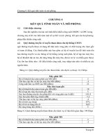
Upload
GSM
14 Kbit/s
14 Kbit/s
40 Kbit/s
54 Kbit/s
43 Kbit/s
58 Kbit/s
59 Kbit/s
200 Kbit/s
64 Kbit/s
384 Kbit/s
384 Kbit/s
1.800 Kbit/s
1.800 Kbit/s
3.600 Kbit/s
3.600 Kbit/s
7.200 Kbit/s
7.200 Kbit/s
14.400 Kbit/s
GPRS
HSCSD
EDGE
UMTS
HSDPA
HSDPA & HSUPA
(2007)
HSDPA & HSUPA
(2009)
HSDPA & HSUPA
(2011)
(Kbit/s)
(Kbit/s)
Download
Figure 1.11 Technology datarate comparison in up- and downlink.
14
JWBK146-01 JWBK146-Kreher January 9, 2007 22:9
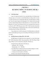
min
max
HSUPA
DSL
50 ms
60 ms
40 ms
75 ms
100 ms
170 ms
400 ms
1.000 ms
300 ms
80 ms
GPRS
HSDPA
UMTS
Figure 1.12 Reduced latency (TTI) in the different mobile technologies.
15
JWBK146-01 JWBK146-Kreher January 9, 2007 22:9
16 UMTS Signaling
MA C
PH Y
L1
L2
L1
L2
L1
L1
L2
HS
DSCH
FP
MA C- D
RL C
HS
DSCH
FP
MA C
c/sh
HS
DSCH
FP
RL C
MA C
hs
HS
DSCH
FP
L2
PH Y
Uu Iub lur
Figure 1.13 HSDPA protocol architecture.
HSDPA there is a new entity, the MAC-hs. It is used in the Node B to ensure a high performance.
MAC-hs handles layer-2 functions of the HS-DSCH and includes:
r
HARQ protocol handling, including generation of ACK and NACK messages.
r
Re-ordering of out-of-sequence subframes. (Normally a function of the RLC protocol, but
not implemented for HS-DSCH. MAC-hs handles the critical RLC tasks; subframes may
arrive out of sequence as a result of the re-transmission activity of the HARQ processes.)
r
Multiplexing and de-multiplexing of multiple MAC-d flows onto/from one MAC-hs stream
r
Downlink packet scheduling.
Control Plane
HSDPA requires modifications of the UTRAN. Some examples are:
r
Radio Resource Control (RRC) protocol, responsible for different UTRAN specific functions
(e.g. radio bearer management).
r
Node-B Application Part (NBAP) enables the RNC to manage resources in the Node-B; the
HS-DSCH is an additional Node-B resource, which is managed by the NBAP protocol, too.
r
Radio Network Subsystem Application Part (RNSAP), on the Iur interface between two
RNCs is adopted, as in HSDPA resources in the Node B, is managed by a Serving RNC
which is different from the Node B’s Controlling RNC.
User Plane
Relevant in the user plane for the HS-DSCH transport blocks is the HS-DSCH Frame Protocol
(HS-DSCH FP). It controls the ‘packaging’ of Transport Blocks (basic data unit from MAC
to physical layer) into a transmission format for the UTRAN network (ATM-based in 3GPP
Rel. 99). Additionally Node B and transport channel synchronization is supported. The flow
control of MAC-d Packet Data Units (PDUs) in the HS-DSCH between RNC and Node B is
achieved by dedicated HS-DSCH FP messages (Figure 1.14).
A Capacity-Request goes from RNC to Node B. It indicates “data ready for transmission”.
The Node B answers with a Capacity-Allocation message. It contains a number (if any) of