Software Engineering (phần 3) pot
Bạn đang xem bản rút gọn của tài liệu. Xem và tải ngay bản đầy đủ của tài liệu tại đây (2.37 MB, 40 trang )
,
'
!
E :a
.
5 XTREME PROGRAMMING 75
' !
falling apart. ln fact, the incremental m odel does not distinguish between developing '
,
a product and enhancing (maintaining) it; each enhancement is merely an additional
build. i
. All too frequently, the requirements change while development is in progress',
this problem is discussed in greater detail in Section 16.4.4. The llexibility of the
incremental model gives it a major advantage over the waterfall and rapid prototyping
models in this regard. On the negative side. the incremental model too easily can I
degenerate into the build-and-lix approach. Control of the process as a whole can be
d becomes a maintainer's l
. lost, and the resulting product, instead of being open-ende , !
; nightmare. In a sense, the incremental m odel is a contradiction in term s, requiring @
, the developer to view the product as a whole in order to begin with a design that 1
will support the entire product, including future enhancements, and simultaneously i1
f
to view that product as a sequence of builds, each essentially independent of the next. j
Unless the developer is skilled enough to be able to handle this apparent contradiction,
the incremental model may lead to an unsatisfactory product. il
ln the incremental model of Figure 3.4, the requirements, specilications, and 1)
k
il architectural design all must be completed before implementation of the various builds
'
,
j .p7 commences
.
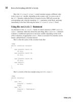
A more risky concurrent version of the incremental model is depicted in j1
; Figure 3.5. Once the client's requirem ents have been elicited, the specifications of the t
.
f
lirst build are drawn up. W hen this has been completed, the specification team tunzs r
,
to the specihcations of the second build while the design team designs the hrst build. !
'
l ith each team using information 1' Thus
,
the various builds are constructed in paralle , w I
gained in al1 the previous builds. I
1 This approach incurs the real risk that the resulting builds will not fit together. !j
c W ith the incremental model of Figure 3.4, the need for the specihcation and architec-
e tural design to be com pleted before starting the hrst build means an overall design at
a the start. W ith the concurrent incremental model of Figure 3.5, unless the process is
y monitored carefully, the entire project risks falling apart. Nevertheless, this concur- ,
rent model has had some successes. For example, it was used by Fujitsu to develop a '
v large-scale communieation system (Aoyama, 19931.
n
s
1.
C - -
d a.5 EXTREM K PR/IRAM M IN/
t- t'
il
e Extreme programming (Beck. l 9991 is a somewhat controversial new approach to i
n software development based on the incremental model. The hrst step is that the soft- j
rs ware development team determines the various features (stories) that the client would 'j
lt like the product to support. For each such feature, the team informs the client how !
e long it will take to implement that feature and how much it will cost. This tirst step i
d corresponds to the requirements and specification phases of the incremental model r'
I
'e (see Figure 3.4)
Ff The client selects the features to be included in the each successive build us-
1- ing cost-beneht analysis (Section 5.2), that is, on the basis of the time and the cost .1
lt estimates provided by the development team as well as the potential benetits of the I
i.
t
)
.
p.i
Please purchase Image To PDF Converter on to remove this message, thank you.
Build 1:
implementation, DefiverS
pecifications Design i
ntegration to client
N
N . -
N
N
N
N. -
N.
N
Implementation, DeliverB
uild 2: Specifications Design i
ntegration to client
N
N <
N
N
N
N. -
N
N
p '*' I
mplementation, DeliverB
uild 3: Specifications Design i
ntegration to client
N
N N
N
N
N.
N N
N
N
! ! !
- -
specification team
- - - nesign team pn.la ,a. qrxzmlfioo.izxrx. ra : lmplementation, Deliver
Implementation/integration team -u'''''- -' '''''-%''''u''''''WM* '-?= 'hd'' integration to client
Flgure 3.5 More risky concurrent incrementul model.
Please purchase Image To PDF Converter on to remove this message, thank you.
L
)
a.* SYNCHRONIZE-AND-SIABILIZE MopEk 17 i
' b ild is broken down into smaller pieces, i
:
1feature to his or her business
. The proposed u f
termed tasks. A program mer first draws up test cases for a task. Then, working with '
a partner on one screen Qmir programming) (Williams, Kessler, Cunningham, and 'j
Jeffriess 20001. the programmer implements the task, ensuring that all the test cases '
work correctly. The task then is integrated into the current version of the product.
ldeally, im plementing and integrating a task should take no more than a few hours. In
general, a number of pairs implement tasks in parallel, so integration can take place
continuously. The test cases used for the task are retained and utilized in all further j
integration testing.
A number of features of extreme programming (XP) are somewhat unusual:
1. The computers of the XP team are set up in the center of a large room lined with
small cubicles.
2. A elient representative works with the XP team at al1 times.
;3
. No individual can work overtime for two successive weeks. :,
.
k ;4
.
There is no specialization. Instead, all m em bers of the XP team work on specih- t
.
'
'
Jl
cations, design, code, and testing. j,
5. As in the more risky incremental model depicted in Figure 3.5, there is no overall l
:
design phase before the various builds are constructed. lnstead, the design is :
modised while the produet is being built. This procedure is termed refactoring. '!l
W henever atest case will not run, the code is reorganized until the team is satisfied g
design is simple, straightfom ard, and runs all the test cases satisfactorily. 1
.
that the
XP has been used successfully on a number of small- and medium-size projects. .'
These range from a 9 person-m onth shipping tariff calculation system to a l 00 person-
year cost analysis system gBeck, 19991. The strength of XP is that it is useful when
the client's requirements are vague or changing. However, XP has not yet been used
widely enough to determine whether this version of the incremental model will fulfill iI
its early promise. j
i
a.* SYNtHR/NIZK-ANP-STABILIZE @pKk
14
Microsoft, lnc., is the world's largest manufacturer of commercial off-the-shelf soft- l
I 1
*
-
*
ware. The majority of its packages are built using a version of the incremental j.
model that has been termed the synchronize-and-stabilize model (Cusumano and ki
1tE
Selby, l 9971. y''I
is conducted by interviewing numerous potential 1.The requirements analysis phase
tomers for the package and extracting a list of features with priorities set by the 14cus
j 'customers
. A specihcation doeument is drawn up. Next, the work is divided into three .
or four builds. The tirst build consists of the most critical features, the second build :
consists of the next most critical features, and so on. Each build is carried out by ,
a number of small teams working in parallel. At the end of each day a11 the teams
I
l
i
t11 .
q.
l:.
Please purchase Image To PDF Converter on to remove this message, thank you.
I
l
t :
l !
i
' !
y* t u A p T z R a * Solw are tife-cytle M odels
. :
j '
synchronize, that is, they put together the partially completed components and test1 1
.
and debug the resulting product. Stabilization is performed at the end of each build.
Any remaining faults that have been detected are fixed and the build isfrozen; that is,
no tkrther changes w ill be made to the specitications.
( The repeated synchronization step ensures that the various components always
1 i work together
. Another advantage of this regularexecution of the partially constructedi i
j ; product is that the developers obtain an early insight into the operation of the product
! ë and can modify the requirements, if necessary, during the course of a build. The
1 I
model even can be used if the initial specihcation is incomplete. The synchronize-
and-stabilize model is considered further in Section 4.5, where team organizational
l details are discussed
.
' The spiral model has been left to last because it incorporates aspects of a1l the
other models.
;
1 -
' a.y $pj k opKk
Alm ost always, an element of risk is involved in the developm ent of software. For ex- .
; ample, key personnel can resign betbre the product has been adequately docum ented.
.
5
.
.
'
The manutacturer of hardware on which the product is critically dependent can go
.
bankrupt. Too much, or too little, can be invested in testing and quality assurance. AF p
'
ter spending hundreds of thousands of dollars on developing a major software product.
k technological breakthroughs can render the entire product worthless. An organization
i m ay research and develop a database management system
,
but before the product can!
1 be marketed
,
a lower-priced, functionally equivalent package is announced by a com-1
l petitor. The components of a product built using the incremental model of Figure 3.5
l t fit together
. For obvious reasons, software developers try to minimize such1 j may nOt
1 l isks wherever possible
.r
1 . One way ol minimizing certain types ot risk is to construct a prototype. As
1 I described in Section 3
.3, an excellent way of reducing the risk that the delivered
product w ill not satisfy the client's real needs is to construct a rapid prototype during :
'
the requirements phase. During subsequent phases, other sorts of prototypes may be .
i appropriate
. For example, a telephone company may devise a new, apparently highlyi
.
! effective algorithm for routing calls through a long-distance network. If the product is
, .
implemented but does not w ork as expected, the telephone company will have wasted
,
the cost of developing the product. ln additions angry or inconvenienced custom ers
'
may take their business elsewhere. This scenario can be avoided by constructing a
prototype to handle only the routing of calls and testing it on a simulator. In this way,
: the aetual system is not disturbed
, and for the cost of implementing just the routing1
' , algorithm, the telephone company can determine whether it is worthwhile to develop
an entire network controller incorporating the new algorithm .
i The idea of minimizing risk via the use of prototypes and other means is the
i concept underlying the spiral model (Boehm
. 19881. A simplistic way of looking at1 )
:
: j this life-cycle model is as a waterfall model with each phase preceded by risk analysis, .i
' hown in Figure 3.6. (A portion of that figure is redrawn as Figure 3.7, to reiectas s
1
Please purchase Image To PDF Converter on to remove this message, thank you.
'
!
'
a-y splu k MooEk yp 4
.
'
test the tel'm spiral model.j Before commencing each phase, an attempt is made to control 'I
ild. (Or resolve) the risks. If it is impossible to resolve al1 the signihcant risks at that stage. :1
t is then the project is immediately terminated. :t ,
Prototypes can be used effectively to provide information about certain classes
of risk. For example, timing constraints generally can be tested by constructing a pro-rays
ted totype and measuring whether the prototype can achieve the necessal'y performance.c
juct lf the prototype is an accurate functional representation of the relevant features of
The the product, then measurements made on the prototype should give the developers a j
ize- good idea as to whether the timing constraints can be achieved.t
I Other areas of risk are less amenable to prototyping. For example, there often is aana
risk that the software personnel necessary to build the product cannot be hired or that
k the key personnel may resign before the project is complete. Anotherpotential risk is that a
Risk analysis U iik ana
-j is s .j ijw - - - - - - ,
Rapid - - u Changed I !1
f * - - e * Uprototype g
.
reyuirements I rkI
- - - - - -
a I ,
Verify I I Verify I j
u - - - - - - - 1 ,1 I t
I !!
C CX- Risk analysis l 11
1 ; .1
lted. s ecification
- - . I j'r'
- - - - - - - - - -
n go phase I 1 .
: !
Af- verify I I '
luct 1 l l
' j j
ttion jRi
sk analysis 1
L Can I ID
esign j
lOm- hase - - - - - - - 1 lP
II I 1z 3
.5 verify I ! l
I
such I I I
l l I
Risk analysis l 1 I
h. As jl
Irered Implementation 1
- - w 1 1
phase j !
lring 1 I
.Test I I
ty be l I jl
L h1y l I l 1 :#
pl I l I I
;ct is Risk analysis j I IE
1 I 4 I '!
àsted Integration 1 j l 1 @
phase I 1 1 I 1.mers
;
ing a Test l I I I $1
1 l l 1 q
'
Way, E'
! .
uting +. Development Maintenance i
relop - - -+' Maintenance phase
i
s the R
etirement
ng at
llysis
,
FI@ur* a.* Simplistic version of spiral model, i'zflect
-
1
$7
)L
Please purchase Image To PDF Converter on to remove this message, thank you.
'
1
( '
I j :
i '
.
j )
'
! ao t u A p v : . a . so- are ufe-cytle M odels :
l
.
) .l
.
:) . .
y l '
. .
analysis
! Risk
1 arlalysis !
1 ê
'
! Risk
1 . analysis .
I
i R iSk
j $ anajysis
. l
i R. a,
:
I Rapid
1 Verify prototype
1
1 verify specification
q 1
. r Verify D
esign
. Verify
.
- r
.
i lmplementation
ë .
i .
'
g)Integration
i .
I j , '
'
.
Flgure a.y Fortion of Figure 3.6 redrawn as a spiral. :
.
!
1 .
: particularteam m ay not be competentenough to develop a specific Iarge-scale product
.
'
! A successful contractor w ho builds single
-
family homes probably would not be able 'i l
y 1 to build a high-rise oftice complex. ln the same way, there are essential differences
j 1
j j between small-scale and large-scale software, and prototyping is of little use. This risk '
I tbe resolved by testing team performance on a much smaller prototype in which1 . canno
1 team organizational issues specific to large-scale software cannot arise
.
Another area .'j
: of risk for which prototyping cannot be employed is evaluating the delivery promises )l
) of a hardware supplier. A strategy the developer can adopt is to determine how well
: E.
previous clients of the supplier have been treated, but past performance by no means .
.
5 is a certain predictor of future perform ance
.
A penalty clause in the delivery contract C
. is one way of trying to ensure that essential hardware will be delivered on time, but
.
what if the supplier refuses to sign an agreement that includes such a clause? Even '
'
with a penalty clause, late delivery may occur and eventually lead to leaal action 3
.
.
- -' ''
'
''''' t
that can drag on for years. In the m eantim e, the software developer m ay have gone
:
. bankrupt because nondelivery of the promised hardware caused nondelivery of the
'
; promised software. ln short, whereas prototyping helps reduce risk in some areas, in .
I j .:
j other areas it is a partial answer at best, and in yet other areas it is no answer at all. .
The full spiral model is shown in Figure 3.8. The radial dimension represents '
'
)
I cumulative cost to date, the angular dimension represents progress through the spi- .
,
ral. Each cycle of the spiral corresponds to a phase. A phase begins (in the top Ieft ';
, j quadrant) by determining objectives of that phase, alternatives for achieving those '
y ' . ,.
I .
; .i
1
Please purchase Image To PDF Converter on to remove this message, thank you.
1'
a.y 5pIRAk M ODEL *1
1
Cumulative l
cost
' Progress
through
steps E
valuate alternatives,D
etermine l identif
y, resolve risks
objectives, i$
'
alternatives, !
constraints I njsk !
analysis 'Risk
Risk analysis
1
.
,
-
1
analysis
- .
- -
- 1
'- Opera- 1
Risk I tional l
' analysis Prototype
rototype @P
.Commitment Prototype 1 Prototype 2
RevieW -
- . -
. - .
.
x -
-
ymujatjons, mo els, benchm rks l
partition Requirements plan
Life-cycle plan l concept of - - - - - -
- -
: .
operation software oetailed '
require- Software design '
' ments product '
Develop- Requirements design r' F
ment plan validation l Code I
I
I I
.
I Unit )I
I !:lntegration oesign validation I test I
and test and verification I lnte- I '
jp I a n 1 g r a t i o n I
Plan next phase Accep-
j test rl
.
tance II
Implementation test'
if,, .Develop, ver
r. next-level product
Flgur. a.@ Full spiral model (Boehm, 1 988). (@1 988, IEEE.) 1$s i
k l ';
i t
a
objectives, and constraints imposed on those alternatives. This process results in as j
LI strategy for achieving those objectives. Next, that strategy is analyzed from the view-
point of lisk. Attempts are made to resolve every potential risk, in som e cases bys
t building a prototype. lf certain risks cannot be resolved, the project may be termi-l
t nated immediately', under some circumstances, however, a decision could be made to '1
. .
continue the project but on a signihcantly smaller scale. If al1 risks are successfully :n
resolved, the next development step is started (bottom right quadrant). This quadrant :n
of the spiral model corresponds to the pure waterfall model. Finally. the results of !e
:
that phase are evaluated and the next phase is planned.e
The spiral m odel has been used successfully to develop a wide variety of products.n
In one set of 25 projects in which the spiral model was used in conjunction with other
means of increasing productivity, the productivity of every project increased by atS
least 50 percent over previous productivity levels and by 100 percent in most of the
rt projects gBoehm, 19881. To be able to decide whether the spiral model should be used
for a given project, its advantages and disadvantages now are assessed.e
(
; '
Please purchase Image To PDF Converter on to remove this message, thank you.
'
'
.
l
j ' 7!
i
4 l .''
i l
.
a2 t u A p T . R a . soe ore Klfe-cyele Modelsl i
I : :'.
2 : a.Kl A xAkysls o: #u: sploxk M opek
li .
EE
.!
i The spiral model has a number of strengths. The emphasis on alternatives and con- .
1 straints supports the reuse of existing software (Section 8. 1) and the incorporation of '1
, software quality as a specific objective. In addition, a common problem in softwarel
1 ! development is determining when the products of a specific phase have been ade
-I - .
l 1 quately tested. Spending too much time on testing is a waste of money, and delivery
1 I f the product may be unduly delayed
.
Conversely, if too little testing is performed,I O
I h the delivered software may contain residual faults resulting in unpleasant con t en
,1
@ sequences for the developers
. The spiral model answers this question in term s of thel
,
i risks that would be incurred by not doing enough testing or by doing too much test-
1 ing
.
perhaps most important, within the structure of the spiral model. maintenance isI j
.
simply another cycle of the spiral; essentially, no distinction is made betw een mainte-
nance and development. Thus, the problem that maintenance sometim es is maligned 'i
1 by ignorant software professionals does not arise, because maintenance is treated the
! : 'same way as development
.
'
l There are restrictions on the applicability of the spiral m odel
. Specifically, in its:
'
'
present form, the model is intended exclusively for internal development of large-
scale software (Boehm, 19881. Consider an internal project, that is, one where the
1 developers and client are mem bers of the same organization
.
lf risk analysis leads to1
the conclusion that the project should be terminated, then in-house software personnel '(
can be simply reassigned to a different project. However, once a contract has been
! signed between a development organization and an externalclient, an attempt by either
.
side to terminate that contract can lead to a breach-of-contract lawsuit. Therefore, in t
k : the case of contract software, all risk analysis must be performed by both client and
1 developers before the contract is signed and not as in the spiral model
.
1
i A second restriction on the spiral model relates to the size of the project. Specifi-1
.
' cally, the spiral model is applicable to only large-scale software. lt m akes no sense to
,
i
( perform risk analysis if the cost of performing the risk analysis is comparable to thei
j cost of the project as a whole or if performing the risk analysis would significantly
j affect the protit potential. Instead, the developers should decide how much is at risk
E
'
and then decide how m uch risk analysis, if any, to perform.
A major strength of the spiral model is that it is risk driven. but this also can be a
. ;
'
: weakness. Unless the software developers are skilled at pinpointing the possible risks
and analyzing the risks accurately, there is a real danger that the team may believe '
that all is well at a time when the project, in fact, is headed for disaster. Only if the :
members of the development team are competent risk analysts should managem ent '
,
decide to use the spiral model.
. !
I
( '
j ' .i
!
I .
' t a.@ @ BJKtT-@ RIKNTZP klyz-tytkz opzks'
$1 .
'
I:
' Experience with the object-oriented paradigm has shown that the need for iteration! 1
J ( j between phases or portions of phases of the process appears to be more common with
: ' the object-oriented paradigm than with the structured paradigm. Object-oriented life- '1
.
,
i
2
.
Please purchase Image To PDF Converter on to remove this message, thank you.
i
a.a OBJKT-ORIENTED LIFE-CYCLE M ODELS ea
i
cycle models have been proposed that explicitly reflect the need for iteration. One 1
h model is the fountain model gl-lenderson-sellers and Edwards, 19901 shown in 1suc
1Fi
gure 3.9. The circles representing the various phases overlap, explicitly reiecting an j
overlap between activities. The arrows within a phase represent iteration within that 1
!
phase. The maintenance circle is smaller, to symbolize reduced maintenance effort l
when the object-oriented paradigm is used.
!In addition to the fountain m odel
, other object-oriented life-cycle models have
been put forward, including recursive/parallel life cycle gBerard, 19931, round-trip 1
gestalt design gBooch, l 9941, and the model underlying the unified software develop-
r
ment process (Jacobson, Booch, and Rumbaugh, l 9991. Al1 these models are iterative, I
incorporate some form of parallelism (overlap of activities), and support incremental
development (Section 3.4). The danger of such life-cycle models is that they may i
be misinterpreted as simply attem pts to make a virtue out of necessity, and thereby i
1
lead to a totally undisciplined form of software development in which team members ;
move almost randomly between phases, tirst designing one piece of the product, next I
analyzing another piece, and then implementing a third piece that has been neither l
analyzed nor designed; the Just in Case You W anted to Know box on page 84 gives
.
more on this ulzdesirable approach. A better way to proceed is to have as an overall ; '
.
obiective a linear orocess (such as the rapid Drototvpinc model of Section 3.3 or the
:
-
' 't' - * * -'' ''' '-''''' i
central vertical line in Figure 3.9) but appreciate that the realities of the object-oriented
q'
j ,paradigm are such that frequent iterations and rehnements certainly are needed.
i
l
1.!
1.
'
!
Maintenance Fudher
development 1 '
C/CrYtiORS
modc ' j
; i
Implementation and
-
ii
ntegration phase l
l
lmplementation
phase
Object-oriented
design phase
!
Object-oriented
analysis phase '
Requirements
phase l
L
L
Flguee a.@ Fountain model.
:
Please purchase Image To PDF Converter on to remove this message, thank you.
! 1 t
!l
.
1 .
: ë
b 1!
j a. t H A > T : R a . so- ore Life-tytle Modelsi
j I
1 q
'
1 I
Jus: IN QASE You W ANT:P To Kwow
;
!
l w hen the members of the development team move in object-oriented paradigm. However, just as the word
essentially haphazard fashion from one task to another, hacker now has a pejorative context in addition to itsl
1 this is sometimes referred to as CABTAB (code a bits original meaning. so CABTAB now is also used in a
j : test a bit)
. The acronym initially was used in a positive derogatory sense to refer to this undisciplined approachI
.
' t sense to refer to successful iterative modelss such to software development. ,
l ! as those that have been used in conjunction with the
! )
! .
j '
I ë
1 !
j : T
! '
f
'
1
E 1 It might be suggested that this problem is sim ply a consequence of the relative
, newness of the object-oriented paradigm. As software professionals acquire more ex-
perience with object-oriented analysis and object-oriented design, the argument goes,
è and as the w hole discipline matures
,
the need for repeated review and revision will de- '
L crease. To see that this argument is fallacious. consider the various life-cycle models
1 previously described in this chapter. First came the waterfall model (Section 3.2) with1
.
its explicit feedback loops. The next major dcvelopment was the rapid prototyping
.
' model (Section 3.3)., one of its major aims was to reduce the need for iteration. How-
l ever, this was t'ollowed by the spiral model (Section 3.7). which explicitly reflects an
iterative approach to software development and maintenance. In addition, it has been
! shown Il-loniden
, Kotaka, and Kishimoto, l 9931 that backtracking is an intrinsic as-!
1 ect of the Coad-
Yourdon technique for object-oriented analysis (Coad and Yourdon,l I P
1 1991a1 and it is likely that similar results hold for the newer object-oriented analysisJ ,
,
techniques as well. In other words, it appears that iteration is an intrinsic property of .
1 '
software production in general and the objeet-oriented paradigm in particular.
l
j '
! '
! j ,
!
l
;t
! a.@ QOM PARIS@N OF LIFE-W tLK opEk:
j '
: Six different classes of software life-cycle models have been exam ined with special
! ;
attention paid to some of their strengths and weaknesses. The build-and-hx model
(Section 3. l ) should be avoided. The waterfall model (Section 3.2) is a known quan-
'
tity. Its strengths are understood and so are its weaknesses. The rapid prototyping
model (Section 3.3) was developed as a reaction to a specific perceived weakness
'
k in the waterfall m odels that the delivered product m ay not be what the client really
' 1
u needs. Less is known about the newer rapid prototyping model than the familiar
'
watedall model, and the rapid prototyping model m ay have som e problem s of its
i described in chapter l0
. One alternative is to combine the strengths of both: own, as
l models
,
as suggested in Section 3.3. l . Another is to use a different model, the incre-: !
j j mental model (Section 3.4). This model, notwithstanding its successes, also has some1
1 drawbacks. Extreme programming (Section 3.5) is a controversial new approach. The
: 1
Please purchase Image To PDF Converter on to remove this message, thank you.
;
a.@ CoMpAmsoN oF LIFE-CYCLE MODELS *5
i
synchronize-and-stabilize model (Section 3.6) has been used with great success by
Microsoft, but as yet there is no evidence of comparable successes in other corporate
cultures. Yet another alternative is to use the spiral model (Section 3.7) but only if
the developers are adequately trained in risk analysis and risk resolution. A further
- (21 f
actor that needs to be considered is that, when the object-oriented paradigm is used,ts
the life-cycle model needs to be iterative', that is, it must support feedback (Sectiona i
la 3.8). The strengths and weaknesses of the various life-cycle models of this chapter )l
in Figure 3.10. lare summ arized
;
Each software development organization should decide on a life-cycle model 1
appropriate for that organization, its management, its em ployees, and its software i
lprocess and vary the model depending on the features of the specific product currently
j
under development. Such a model will incorporate appropriate aspects of the various 11
life-cycle models, utilizing their strengths and minimizing their weaknesses. 1
I .
ative
e eX- !
ioes, ktife-cvtle M odel s'reng'hs W eo nesses
11 de- -
ldels fi d I (section 3.
1 ) Fine for short programs that will not Totally unsatisfcctory for '''Build-and- x mo e
.
with require any maintenance nontrivial programs
.
.
'
ing '.P
low- Waterfoll model (Section 3.2) Disciplined approach Delivered product may not .
meet clientzs needs '.
:ts an Document-driven
:
been
zapid prototyping model Ensures that delivered product Not yet proven beyond u11 doubt '
c as- jkentzs needs(Section 3
.
3) meets c
rdon,
tlysis lncrementcl model (Section 3.:) Maximizes early return on Requires open orchitecture
4y of investment Mcy degenerate into build- i
1Promotes maintainubility and-fix I
lExtreme programming (Section 3.5) Moximizes eariy return on Hos not yet been widely used
investment
W orks well when client's
requirements ore vague
Synchronize-ond-stabilize model Future users' needs are met Hcs not been widely used other
(Section 3.6) Ensures components can be thon at Microsoftlecial i
.
successfully integrated '1nodel
1 .
uan- !1 I d
eI (section 3,7) Incorporates features of a11 the Can be used only for Iarge- !Spira mo
fping b d
els scole, in-house products !'a OVe mo
kness D
evelopers have to be
really k isk analysis 'competent n r
niliar and risk resolution '
of its
h Obiect-oriented models Support iteration within phases, May degenerate into CABTABr bot
(sec#ion 3.8) parallelism be-een phasesLncre
-
som e
l The FIgur* a.l@ Comporison of Iife-cycle models described in this chapter and the section in which each is defined. :
:
i
Please purchase Image To PDF Converter on to remove this message, thank you.
j ' .
t
'
: '
j 1 ,'
1 ; '
) I '
'
! 2 ** t u A p T : R a @ Soe ore tife-cytle Models
1
.
(
i l tua- up Rzvlzw
' t
i ' : 1
! i A number of different life-cycle models are described, including the build-and-fix *
l model (Section 3. l ), waterfall model (Section 3.2), rapid prototyping model (Sec- 'l
.
l tion 3.3), incremental model (Section 3.4), extreme programming (Section 3.5), .
1 k synchronize-and-stabilize model (Section 3
.6), spiral model (Section 3.7), and object- . 3*Qi 1
j l oriented life-cycle models (Section 3.8). ln Section 3.9, these life-cycle models are
1 i compared and contrasted, and suggestions are made regarding choice of life-cycle
k q model for a specilic project. '!
! .
i :
f l
!
:
I 3.3i ï
! ë F@R FURTHKR RKAPIN/:
.
3.#
'
The waterfall model was first put forward in LRoyce, 19701. An analysis of the wa- '
: terfall model is given in the first chapter of (Royce, 19981.
' For an introduction to rapid prototyping
, two suggested books are gconnell and
ï Shafer
, 198% and gGane, 19891. The role of computer-aided prototyping is assessed
,
in gLuqi and Royce, 19921. The February 1995 issue of IEEE Computer contains
several articles on rapid prototyping.
;
A description of the evolutionary delivery model, one version of the incremental z
.;
model. can be found in (Gilb, 19881. The concurrent incremental model is described!
.
'
in gAoyama, 19931. The synchronize-and-stabilize model is outlined in gcusumano z o
l i d Selby
,
1 9971 and described in detail in gcusumano and Selby, 19951. Insights *ani
.
into the synchronize-and-stabilize model can be obtained from (Mcconnell, 19961.1 i z
.
y! E Th
e spiral model is explained in gBoehm, 19881, and its application to the TRW
Software Productivity System appears in gBoehm et al., l 9841. Extreme programming . 3*3
l is described in (Beck
,
19991 and LBeck, 20001; refactoring is the subject of gFowler 3.@1
, et al., 19994.(
'
1 1 Risk analysis is described in LBoehm. l99 l ; Jones, l 994c) Karolak, 1996; and . a.1@
! Keil, Cule, Lyytinen
, and Schmidt, 19981. The May/lune 1997 issue of lEkx software
l i 10 articles on risk management
.
'
'
l Conta ns
! ' Object-oriented life-cycle models are described in (Henderson-sellers and Ed- g
.! 1( :
! ' wards, 1990; Rajlich, 1994) and Jacobson, Booch, and Rumbaugh, l 9991.
f M any other Iife-cycle models have been put forward. For example. a life-cycle
'
model that emphasizes human faetors is presented in gMantei and Teorey. 19881, and
'
.
gRajlich and Bennett, 20001 deseribes a maintenance-oriented life-cycle model. A
life-cycle model recommended by the Software Engineering Laboratory is described .
:
in (Landis et al., l 9921. The July/August 2000 issue of IEEE Software has a variety of1
l apers on software life-cycle models, including (Williams, Kessler. Cunningham, and 2. P
Jeffries, 20001, which describes an expeliment on pair programming, one component!
! of extreme programming
.
The proceedings of the International Software Process: l
W orkshops are a useful source of information on life-cycle models. CISO/IEC 12207. '. (
j 19951 is a standard for software life-cycle processes.
. /
i )
:
l .
Please purchase Image To PDF Converter on to remove this message, thank you.
l ,
REFERENQES %7
!
iPRoekzM s t
l3
.
1 Suppose that you have to build a product to determine the inverse of 3.74857 1 to four j
decimal places. Once the product has been implemented and tested, it will be thrown
away. W hich life-cycle model would you use? Give reasons for your answer. i
3.2 You are a software engineering consultant and have been called in by the vice- .
!
president for hnance of Deplorably Decadent Desserts, a corporation that manu-
:
factures and sells a variety of desserts to restaurants. She wants your organization to
build a product that will monitor the company's product, starting with the purchasing jof the various ingredients and keeping track of the desserts as they are manufactured 1
;
'
and distributed to the various restaurants. W hat criteria would you use in selecting a
Iife-cycle model for the project?
involved in developing the software of Problem 3.2. How would you l3
.3 List the risks (
attempt to resolve each risk? I1
3.4 Your development of the stock control product for Deplorably Decadent Desserts is l
I l
highly successful. As a result, Deplorably Decadent Desserts wants the product to
be rewritten as a COTS package to be sold to a variety of different organizations
;
that prepare and sell food to restaurants as well as to retail organizations. The new
product therefore must be portable and easily adapted to new hardware and operating t
systems. How do the criteria you would use in selecting a life-cycle model for this t
project differ from those in your answer to Problem 3.2? $'1
3.5 Describe the sort of product that would be an ideal application for the incremental j
model. j
3.: Now describe the type of situation where the incremental model might lead to 1
1difh
culties. 5l
I3
.
7 Desclibe the sort of product that would be an ideal application for the spiral model. j ;
3.8 Now describe the type of situation where the spiral model is inappropriate. !
3.9 W hat do waterfalls and fountains have in common? W hat do the waterfall model and ;
fountain model have in common? How do they differ? i
t -3
.
lQ (Term Projeet) Which software life-cycle model would you use for the Broadlands ; I
Area Children's Hospital project described in Appendix A? Give reasons for your .
ansW er.
3.1 1 (Readings in Software Engineering) Your instructor will distribute copies of (Beck,
19991. Would you like to work in an organization that uses extreme programming? 1
I
'
RKFERENtKS
E (Aoyamas 19931 M. AOVAMA, ''Concurrent-Development Process Model,'' IEEE Computer
; 10 (July 1 993), pp. 46-55.
(Beck, 19991 K. BECK, 'Ymbracing Change with Extreme Programminp'' IEEE Computer
32 (October l 999), pp. 70-77.
Please purchase Image To PDF Converter on to remove this message, thank you.
1 i
k 1
f
'
2
j Et
1
(
- -
. - .e n >1
i @
.
@
'
I
) .
l t!
1 E1
1
i l
I (
i
I .
1
j
J
1
I '
'
j
J l
l ithout competent
,
well-trained software engineers, a software project is doomed to failure. However,!
i having the right people is not enough', team s m ust be organized in such a way that the team m embers can
) j work productively in cooperation with one another. Team organization is the subject of this chapter.
1
( :
:
'
f
.
1
' $ 4.1 TEAM @ ROANIIATION!
)
1 k M ost products are too large to be com pleted by a single software professional within 1
!
l the given time constraints
. As a result, the product must be assigned to a group of 'f
. (
'
I professionals organized as a team. For example, consider the specihcation phase. d
) . To specify the target product within 2 months, it may be necessary to assign the '
1 .
è task to three specification specialists organized as a team under the direction of the
specification manager. Similarly, the design task may be shared between mem bers of
i
; :1 1 the design team
.
! ' Su ose now that a product has to be coded within 3 months
,
even thoughI ; PP
I
1 person-year of coding is involved (a person-year is the amount of work that can be
: ! d b ne erson in l year)
.
The solution is apparently simple: lf one programmer '
.
one y o p
è can code the product in 1 year, four programmers can do it in 3 m onths.
!
, j This. of course, does not work. ln practice, the four programmers may take '
: nearly a year, and the quality of the resulting product w ell may be lower than if
!
! one programmer had coded the entire product. The reason is that some tasks can be
shared. but others must be done individually. For instance, if one farmhand can pick a
l : strawberry held in 1 0 days, the same strawberry field can be picked by 10 farmhands
i ' i ) day
.
On the other hand, one woman can produce a baby in 9 months, but this feat ': j n
l l cannot possibly be aecomplished in 1 month by nine women.
1 1
J 1 ln other words, tasks like strawberry picking can be fully shared', others, like
' baby production, cannot be shared. Unlike baby production, it is possible to sharel i
; i
'
l ! j
i 90
! J
'
t .
Please purchase Image To PDF Converter on to remove this message, thank you.
!
)
l
*.4 n AM O RGANIIATION *1
.
ë
implem entaticm tasks between members Of a team by distributing the coding among S
I
'
the team members. However, team program ming also is unlike straw berry picking in
that team mem bers have to interact with one another in a meaningful and effective
way. For example, suppose Jane and Ned have to code two modules. m 1 and m2. 3
A number of things can go wrong. For instance, both Jane and Ned may code ml 2
land ignore m2
. Or Jane may code m 1 , and Ned may code m2. But when ml calls .
m2 it passes four arguments', Ned has coded m2 in such a way that it requires five
arguments. Or the order of the arguments in m 1 and m2 may be different. Or the
order may be the same, but the data types may be slightly different. Such problems ï
usually are caused by a decision made during the design phase that is not propagated : 1
tlzroughout the development organization. The issue has nothing whatsoever to do l
I
with the technical competency of the programmers. Team organization is a managerial E
issue', management must organize the programming teams so that each team is highly
productive. .
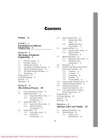
A different type of difficulty that arises from team development of software is I
shown in Figure 4. l . There are three channels of communication between the three i
I
computer professionals working on the project. Now suppose that the work is slipping, j.r,
' a deadline is rapidly approaching, and the task is not nearly complete. The obvious jn
is to add a fourth professional to the team. But the first thing that must 1thing to do
1-happen when the fourth professional joins the team is for the other three to explain
.
jin detail what has been accomplished to date and what is still incomplete
. ln other .1
.
words, adding personnel to a late software project makes it even later. This principle 'j
is known as Brooks 's f'tzw, after Fred Brooks who observed it while managing the j
development of 05/360 (Brooks, 19751. 1!
ln a large organization, teams are used in every phase of software production, :
;
but especially in the implem entation phase, during which programmers work in- !kn
dependently on separate modules. Accordingly, the implementation phase is a prime 1
E)f
candidate for sharinz the task amonz several comouter orofessionals. In som e smaller ! 1
C. = = * * 1
.
àe
L
'
3e ')
'
af j. M
-
x
w
jh N>4
x'
lie
- -e- /
/er
-
-'e
.
e- /
.
/
,e- / 'ke
.
-'e
.
.
e-
' /if
.,
-' / : A
b ''- / :e
ka
ds
:at Flgure *.1 Communication paths
between three computer professionols (solid
ke Iines) and when a fourth professioncl ioins
them (dashed lines).tre
( .
Please purchase Image To PDF Converter on to remove this message, thank you.
J
'
'
( 't i
l ! t
I
l I ë
; @Q e K A p T : R * * Teom s
i(
'
:
'
1
1 organizations, one individual may be responsible for the requirements, specihcations,i i
'
.
and design'. after which the im plementation is done by a team of two or three pro-
.
grammers. Because teams are used m ost heavily during the implementation phase,
l the problems of team organization are felt most acutely during implementation
. ln7 2
4 j the remainder of this chapter, therefore, team organization is presented within the
! l context of implementation, even though the problems and their solution are equally
( i 1(
applicable to a1l the other phases.l
'
.
k There are two extreme approaches to programming-team organization; demo-
1 1 cratic teams and chief programmer teams
. The approach taken here is to describel ' .
l t each of the approaches, highlight its strengths and weaknesses, and then suggest
! i
j p other ways of organizing a programming team that incorporate the best features of
1 ' the two extremes
.I
(
J (
i
I *.2 pzM otRATlt 'EAM A PPR/M H
'
j .
: . l
.
.
.
j The democratic team organization was first described by Weinberg in 1971 gWeinberg,
'
:
,
197 l ). The basic concept underlying the democratic team is egoless programming.
'
,
W einberg points out that program mers can be highly attached to their code. Some- '
.
ï
'
,
: times, they even nam e theirmodules afterthemselves; they therefore see their m odules '
'
as an extension of themselves. The difficulty w ith this is that a programmer who sees
a module as an extension of his or her ego certainly is not going to try to find all the
faults in Efhis'' code or 4ther'' code. And if there is a fault, it is termed a bug, like some1 : 1 insect that has crept unasked into the code and could have been prevented if only
! ;i
the code had been guarded more zealously against invasion. Some years ago, wheni
! j software was still input on punched cards, that attitude was amusingly lampooned
1 by the marketing of an aerosol spray named Shoo-Bug. The instructions on the label1
I .) , solemnly explained that spraying one s card deck with Shoo-Bug would ensure that
l j no bugs could possibly infest the codc.
l W einbern's solution to the oroblem of Droerammers beinc too closelv attached
'
to their own code is egoless programming. The social environment must be restruc-
: 1 tured and so must programmer values
. Every program mer m ust encourage the other) :
E ' ; i members of the team to find faults in his or her code. The presenee of a fault must!
:
not be considered something bad but rather a normal and accepted event; the attitude
of the reviewer should be appreciation at being asked for advice, rather than ridicule
of the programmer for m aking coding errors. The team as a whole develops an ethos,
' a group identity, and modules belong to the team as a whole rather than any one
individual.
'
i '
:
A group of up to 10 egoless programmers constitutes a dem ocratic team. Wein-1
i 2 ! berg warns that management may have difticulty working with such a team
. A fter1
l ' '
, E all, consider the managerial career path. W hen a programmer is promoted to a man- :
1 l
j agement position, his or her fellow programmers are not promoted and must strive to
'
j attain the higher level at the next round of promotions. In contrast, a democratic team!' g is a group working for a common cause with no single leader
,
with no programmers
! !
l E
.
!
:
Please purchase Image To PDF Converter on to remove this message, thank you.
1
I
l
. 1
ea Cm sslcAk CHIEF PROORAMMKR nAM APPROM H @a
trvinc to cet promoted to the next level. W hat is important is team identitv and mutual !
y *' *' *' *. s *' I
respect. 1
Weinberg tells of a democratic team that developed an outstanding product. M an- I
5
I
agement decided to give a cash award to the team 's nominal manager (by desnition, I1
a democratic team has no leader). He refused to accept it personally, saying that it l)
'
!
had to be shared equally among a11 members of the team. M anagement thought that jI
he was angling for more money and that the team (and especially its nominal man- 1
.
ager) had some rather unorthodox ideas. M anagement forced the nominal manager ti
he money, which he then divided equally among the team. Next, the entire lto accept t
t i
t team resigned and joined another company as a team. 1è 1
f The advantages and disadvantages of democratic teams now are presented.
1
E
+ 2.1 A xAkvsls o, TH. p zMotou lt TZAM A ppRoAtu !
ë
'
A major advantage of the democratic team approach is the positive attitude toward j
-
hnding faults. The more faults found, the happier are the members of a democratic j
team. This positive attitude leads to more rapid detection of faults and hence to high- 'j
quality code. But there are some major problems. As pointed out previously, managers l
.
''' ''' -' -' -' ''' ''' - !
'' may have difhculty accepting egoless programming. In addition, a programmer with, ;
'
' 15 ears of experience is likely to resent having his or her code appraised by !say
,
y
-
fellow programmers, especially beginners. l
s
1W
einberg feels that egoless teams spring up spontaneously and cannot be imposed j
S from outside
.
Little exoerimental research has been done on democratic oroeramminz 1
e * x '-' - i
team s, but the experience of W einberg is that dem ocratic teams are enorm ously pro- :
e :ductive
. M antei analyzed the democratic team organization using arguments based on I
Y theories of and experiments on group organization in general rather than speciscally j
n .
on proerammine teams (Mantei, 198 11. She ooints out that decentralized crouos work ; 'd A '
-' '-' - <- -
best when the problem is difficult and suggests that democratic teams should function
:1
well in a research environm ent. lt has been m y expelience that a democratic team :
tt :
also works well in an industrial setting when there is a hard problem to solve. O n a !
number of occasions, I have been a member of democratic teams that have sprung up I jd
spontaneously among computer professionals with research experience. But once the 12
- 11
task has been reduced to the implementation of a hard-won solution, the team must
lr be reorzanized in a m ore hierarchical fashion
,
such as the chief oroerammer team
st '-' * '-' l
approach described in the next section.L
e
e
q, .
i
le j:
I
G a t. AssItAk ZHIEF PR@/RAM M KR1
-
TKAM A PPROM Hlf
1- .
Consider the six-person team shown in Figure 4.2. There are 15 two-person commu-:o
nication channels. In fact, the total number of two-, three-, four-, five-, and six-person ' !R1
groups is 57. This multiplicity of communication channels is the major reason why aCS
Please purchase Image To PDF Converter on to remove this message, thank you.
!
'
! '
i j î
'
k I :
'
!
'
s J E. j
i ** t u A p 4 : w * . Teom s
k i
! j .l
j '. r
!
j j
5 .
l g
I , ;.
l
i :
'
.
! -1
I I
' i j j1
j 'i I y
1 )
: !
l ,
! l1 j j
j '
E i
. p Flgure *.Q Communication paths befween
'
six computer professionals,
j '
2
.
'
t P
rogramming Chief Back-up!
'
1 ' Secretary programmer programmer
:1 I
.
t 1 .
; .
Programmer Programmer Programmeri ! p
.I :
'
j '
l ; l Flguee *.a Structure of classical chief programmer team.
1 i 1'
j
i Il
six-person team structured as in Figure 4.2 is unlikely to be able to perform 36 person-
1 months of work in 6 months; many hours are wasted in meetings involving two or
1
1 1 j more team members at a time.; '
I . I Now consider the six-person team shown in Figure 4.3. Again there are sixi
: 1 but now there are only tive lines of comm unication
. This is the basic! ! Programmers,
:
'
; : 1 concept behind what now is termed the chiefprogrammer team. A related idea was put
' '
( 1
'
forward by Brooks, who drew the analogy of a chief surgeon directing an operation
!
:
i gBrooks, 19751. The surgeon is assisted by other surgeons, the anesthesiologist, and(
é j a variety of nurses. In addition, when necessary, the team uses experts in other areas,
' ! such as cardiologists or nephrologists. This analogy highlights two key aspects of a:
;
: chief program mer team . The first is specialization Each member of the team canies
' j è out only those tasks for w hich he or she has been trained
. The second aspect is 't
! : ' hierarchy The chief surgeon directs the actions of all the other members of the team
.
:
1 l ' and is responsible for every aspect of the operation.
' j ë
'
:
,
1 The chief programmer team concept was formalized by M ills LBaker, 19721. A ,
' j
classical chief programmer team, as described by Baker some 30 years ago, is showni 1
ii I
: . I .(
.
j '
;
;
' !
Please purchase Image To PDF Converter on to remove this message, thank you.
l
a CmssxAL CHIEF PROGRAMMER TEAM APPROACH *5 l
l
2
in Figure 4.3. It consisted of the chief programmer, who was assisted by the back-up 'j
programmer, the programming secretary, and from one to three programmers. W hen
necessary, the team was assisted by specialists in other areas. such as legal or financial il
matters, or the job control language (JCL) statements used to give operating system
commands to the mainframe computers of that era. The chiefprogrammer was both a l
successful manager and a highly skilled programmer who did the architectural design I
and any critical or complex sections of the code. The other team m em bers worked :
on the detailed design and the coding, under the direction of the chief programmer. 'l
As shown in Figure 4.3, there w ere no lines of communication between the pro- I
grammers; al1 interfacing issues were handled by the chief programmer. Finally, the
chief programmer reviewed the work of the other team members, because the chief 1
programmer was personally responsible for every line of code. i1
The position of back-up programmer was necessary only because the chief pro- .
grammer was human and therefore could become ill, fall under a bus, or changejobs. :!
Therefore, the back-up programmer had to be as competent as the chief programmer I
hief programmer. 2in every respect and had to know as much about the project as the c :
In addition, to free the chief program mer to concentrate on the architectural design,
the back-up programmer did black-box test case planning (Section 14.7) and other
tasks independent of the design process. j,
The word secretaty has a number of meanings. On the one hand, a secretary as- 'l
sists a busy executive by answering the telephone, typing correspondence, and so on. :1
lk about the American Secretary of State or the British Foreign Sec- iBut when we ta
l
retary, we refer to one of the most senior members of the Cabinet. The programming j
secretary was not a part-time clerical assistant but a highly skilled, well-paid, central I
lmember of a chief programmer team
. The programming secretary was responsible for !
maintaining the project production library, the documentation of the project. This in- J
cluded source code listings, JCL, and test data. The program mers handed their source
code to the secretary, who was responsible for its conversion to machine-readable 1
I
form, compilation, linking. loading, execution, and running test cases. Programmers ' '
lth
erefore did nothing but program. A1l other aspects of their work were handled by the I .
.n- .
programming secretary. (Because the programming secretary maintained the projector
.
production library, some organizations have used the title Iibrarian.) : i
Recall that what is described here are M ills's and Baker's original ideas, dating
.
ix
back to 197 1 , when keypunches still were widely used. Coding no longer is done
;ic I
that way. Programmers now have their own terminals or workstations in which they jiut
enter their code, edit it, test it, and so on. A m odern version of the classical chief l
nn 1
programmer team is described in Section 4.4.
Ad
tS, .'
t '
a il
es < aa 'uz N :w Y oRx Tl-zs pRozetv
is
The chief program mer team concept was tirst used in 197 l by IBM to automate them
clipping hle ('smorgue'') of the New Ftpr/c Times. The clipping tile contains abstracts
x and full articles from the Ncw York Times and other publications. Reporters and other
members of the editorial staff use this information bank as a reference source.vn
Please purchase Image To PDF Converter on to remove this message, thank you.
! ! l
I 1 ; .
j 1 . .
i ( .
l ,
i i : ** t u A p T : R * . Teoms '.7
! . L.
: 1 .;
1 The facts of the project are astounding. For example, 83
,000 lines of code (LOC): 1
.
1 were written in 22 calendar months
,
an effort of l 1 person-years. After the first year, : aë; ' !
ë only the hle maintenance system consisting of 12,000 LOC had been written. M ost Cl
@ ( of the code was written in the last 6 months
.
Only 21 faults were detected in the ûrst Stj .
. - .
.
5 weeks ot acceptance testing', only 25 turther taults were detected in the first year W1
i f o eration
. Principal programmers averaged one detected fault and 10,000 LOC' j o pj
l t ! per person-year. The file maintenance system, delivered l week after coding was m
i leted
,
operated 20 months before a single fault was detected. Almost half the tcj comp
1 j subprograms, usually 200 to 400 lines of PL/I, were correct on the first compilationl
1 Baker, l 9721 . tc,' j 1'
@ j I Nevertheless, after this fantastic success, no comparable claims for the chief pro- rei
'
grammer team concept have been made. Yes, many successful projects have been rel j
-
, carried out using chief programmer teams, but the figures reported, although satis- . is
1 ! fa
ctory, are not as impressive as those obtained for the New For/t Times project. W hy , te' ; ;I
.
q
:
was the New For/c Iilnes project such a success, and why have similar results not been la
obtained on other projects?
:
One possible explanation is that this was a prestige project for IBM. lt was the:
,
first real trial for PL/I, a language developed by IBM . An organization known for its
I superb software experts, IBM set up a team comprising what can only be described as -
4: their crème de la crème from one division
. Second, technical back-up was extremely
.
,
strong. PL/I compiler writers were on hand to assist the programmers in every way
1
( ; they could, and JCL experts assisted with the job control language. A third possible
explanation was the expertise of the chief programmer, F. Terry Baker. He is what is D
l : now called a superprogralnme6 a programmer whose output is four or hve times that ol1
i 1 of an average good programmer
.
In addition, Baker is a superb manager and leader, wl
;
) j and it could be thathis skills.enthusiasm, and personality werethe reasons underlying pt
ë the success of the project. al
! If the chief programmer is competent
,
then the chief programmer team organi- inl
Ii
j zation works well. Although the remarkable success of the New Fbrk Times project i S4
! ' has not been repeated
,
many successful projects have employed variants of the chief ) e5' j
.,
.
programmer approach. The reason for the phrase variants of the approach is that pl9 1
l j $ the classical chief programmer team as described in (Baker, 19721 is impractical in
' m any w ays. th
(i I '
' hi
é Ir
E *
.a.2 IMpoxtTltAua o: Tu: t' xssltAt tsI:y pwooax zp w
TZAM JkpppoAtu W
' Fe
'
'
Consider the chief program mer, a combination of a highly skilled programmer and St(
, ., , , . x . . - - x . , , , , x .
successlul manager. bucn InUlvlduals are Ulêllckllt to llnd: 1 llere is a Shortage Of highly W
I
.
@ ' skilled programmers as well as a shortage of successtkl managers, and thejob descrip- ' e:
i 1 1 tion of a chief programmer requires both abilities
. It also has been suggested that the alr ;
: .
' lities needed to be a highly skilled programmer are different from those needed 02 i : qtla
' !
'
to be a successful manager; therefore, the chances of hnding a chief programmer te
are small. eli
: !
.
'
,
'
'
j
'
j
'
; ( ) '
1 :
'
.
$ ;
h
: I
: .
Please purchase Image To PDF Converter on to remove this message, thank you.
l
I
l I
*.* BEYOND CHIEF PROGRAMMER AND DEMOCRATIC TEAM5 *V l
I
:
o But if chief programmers are hard to tind, back-up programmers are as rare : j
as hen's teeth. After all, the back-up programmer is expected to be as good as the i IR.
r, I ,
t chief programmer but has to take a back seat and a lower salary while waiting for IIS
t something to happen to the chief programmer. Few top programmers or top managers ;rs
would accept such a role.:ar
)c A program ming secretal'y also is difficult to find. Software professionals are
,as notorious for their aversion to paperwork, but the programming secretary is expected ' q
I
he to do nothing but paperwork a1l day.
r
i
Thus, chief programmer teams, at least as proposed by Baker, are impractical !.on
ito implement
.
Democratic teams also were shown to be impractical but for different )l
reasons. Furthermore, neither technique seems to be able to handle products that )7o
-
require 20, let alone l 20, programmers for the implementation phase. W hat is neededen
!
is- is a way of organizing programming teams that uses the strengths of democratic j
h team s and chief programmer team s and can be extended to the implementation of 'y
larger products. :en
1
; .)he
j
its 1'
.
)
'
aS 'i< * BR @NP QHIEF PR//RAM M KR
zly j
'ay ANp PEM @tRATI: TEAM :
!ble
I
L is Democratk teams have a major strength', namely, a positive attitude toward the linding l
f faults. A number of organizations use chief programmer teams in conjunction liat o
i
Ler, with code reviews (Section 6.2), creating a potential pitfall. The chief programmer is !
ersonally responsible for every line of code and, therefore, must be present during i
.
ng p
!
alI code review s. However, a chief programm er also is a manager and, as explained !
ni- in Chapter 6, reviews should not be used for any sort of perform ance appraisal. '
ect So, because the chief program mer is also the manager responsible for the primary '
;
ief evaluation of the team members, it is strongly inadvisable for that individual to be
hat present at a code review.
in The way out of this contradiction is to remove much of the managerial role from
; 'the chief programmer
.
After all, the difhculty of hnding one individual who is both a I
lhi
ghly skilled programmer and successful manager has been pointed out previously. j
Instead, the chief program mer should be replaced by two individuals: a team Ieader l
who is in charge of the technical aspects of the team's activities and a team manager I
ible for all nontechnical managerial decisions. The structure of the 1who is respons
lting team is shown in Figure 4.4. lt is important to realize that this organizational Iresu
does not violate the fundamental managerial principle that no employee lnd Strtlcturet
i
kly should report to m ore than one manager. The areas of responsibility are clearly delin- 'j
'
ip- eated. The team leader is responsible for only technical management. Thus, budgetary l
the and legal issues are not handled by the team leader, nor are performance appraisals.
jed 0n the other hand, the team leader has sole responsibility on technical issues. The
herefore has no right to promise, say, that the product will be deliv- iteam manager tner
,
ered within four weeks; promises of that sort have to be made by the team leader. The '
!
l
l
Please purchase Image To PDF Converter on to remove this message, thank you.
I 1 l
1 1 h
'
l j i.
l
4 d @* e u A p T : R * @ Team s .
ô t à .1 !!
j Team Teaml
.
,
j manager leader
,
ë l
! l '-x. v
I / N. 'x- L
/ N l l j '
. -x. ;
! / x
( ' N/
N ''x11 N
x! I i
l . 1
1
1 .! I
I 1 Technical management
i ; - - - - Nontechnical management
l i
.
! j
'
i 'Igure #.* Structure of modern programming team.
I ! !
1i ;
1
. ; team leader naturally participates in all code reviews', after all, he or she is personally
,
, ; responsible for every aspect of the code. A t the same time, the team manager is not
'
permitted at a review, because programmer performance appraisal is a function of the
.
.
i
.
team manager. Instead, the team manager acquires knowledge of the technical skills #I
4 of each programmer in the team during regularly scheduled team meetings
. .
'
j :
: ( Before implementation begins, it is important to demarcate clearly those areas
: that appear to be the responsibility of both the team m anager and the team leader
.
,
! For example
,
consider the issue of annual leave. The situation can arise that the team '
j
'
.
; manager approves a leave application because leave is a nontechnical issue, only to '
:
j find the application vetoed by the team leader because a deadline is approaching.
! . The solution to this and related issues is for higher m anagem ent to draw up a policy
1 i j djng areas that both the team manager and the team leader consider to be their
.
1 1 I regar
l ë s onsibility
.
I re p
l what about larger projects? This approach can be scaled up as shown in Figure
!i i 4
.5, which shows the technical managerial organizational structure', the nontechnical .1
! I!
,
side is similarly organized. Implementation of the product as a whole is under the ',
j direction of the project leader. The programmers report to their team leaders, and the' 1
I team leaders report to the project leader. For even larger products, additional levels1 ,
!
: i can be added to the hierarchy
.1
i '. Another way of drawing on the best features of both dem ocratic and chief pro-
! ) 1
: j grammer team s is to decentralize the decision-m aking process where appropriate
.!
'
.
t ' $ The resulting channels of communication are shown in Figure 4.6. This scheme is
1
, useful for the sorts of problems for which the democratic approach is good'
.
that is,
, :
' in a research environm ent or whenever a hard problem requires the synergistic ef-
:
!
,
.
'
fect of group interaction for its solution. Notwithstanding the decentralization
,
the
l
j ' an-ows from level to level still point dow nward', allowing programmers to dictate to
,
'
' the project leader can lead only to chaos.i '
; ? Unfortunately, there is no one solution to the problem of programming team or-
l 1 ganization and
,
by extension, the problem of organizing teams for all the otherphases
.
'
q , ! ;
: t l The optimal way of organizing a team depends on the product to be built, on previ-1
ous experience with various team structures, and on the outlook of the heads of thel1 l
organization. For example, if senior management is uncomfortable with decentralized ': 1
:
'
'
t' 1
r (' :
j 1 .
.
9 1
j '
(
'
.
!
Please purchase Image To PDF Converter on to remove this message, thank you.
(7 = T . lj b( g' = Lt ; ' s . 8* d = = = àJ H Lt . O (R g ' R M % = = T) w;-c. rv 1
.
' rp I w . I cm (7 (7 R ex << . . Cm fv ,-e
Project
Ieader
Team Team Team
Ieader Ieader Ieader
*
< Programmer Programmer Programmer Programmer Programmer Programmer Programmer Programmer
Technical management
Flgwre *.5 Technical managerial organizutional structure for Iarger proiects.
- 2 LL ' - - 772-77 . . - E I . L . 7 T . -77 - . - . . - - . . -
.
. .
.
- .
.
Please purchase Image To PDF Converter on to remove this message, thank you.
Project
Ieader
8
Team Team Team
Ieader leader Ieader
Programmer Programmer Programmer Programmer Programmer Programmer Programmer Programmer
Technical management
Flgu- *.* Decentralized decision-making version of team organizction of Figure :.5 showing communication channels of techniccl mcnagement
.
K. >% % K %' œ = th > > > = C7 C) = &- *% O >. <' rh *-' *- = -' o b'- -' = - ' - '' ' ' '
Please purchase Image To PDF Converter on to remove this message, thank you.
r
)
'
;
r
j'*.s ANtHRONIZE-AND-SIABILIZE TEAMS l@1
i
'
(
'
decision making, then it will not be implemented. Unfortunately, not much research j
has been done on software development team organizations and many of the generally ( 1,
accepted principles are based on research on group dynamics in general and not on !
software development team s. Until experimental results on team organization have
been obtained within the software industry. it w ill not be easy to determine the optim al I
team organization for a specilic product.
.
(
'
E
'
ç
'
+ 5 A NtHRONIIE-ANP-:TABIKIIK TKAM S !
i h
An alternative approach to team organization is the synchronize-and-stabilize team r.
utilized by Microsoft (Cusumano and Selby, l 9971. Microsoft builds large products; !
'
j .forexample
,
W indows 2000 consists of more than 30 millions of lines of code, built by !
:
over 3000 programmers and testers (Business Week Online, 19991. Team organization li
is a vital aspect of the successful construction of a product of this size. g
The synchronize-and-stabilize life-cycle model was described in Section 3.6. The !
success of this model is Iargely a consequence of the way the teams are organized. ;
Each of the three or four sequential builds of the synchronize-and-stabilize model !
is constructed by a number of small parallel teams led by a program manager and 2
consisting of between three and eight developers together w ith three to eight testers )
iwho work one-to-one with the developers
. The team is provided the specihcations of
their overall task; the individual team members then are given the freedom to design i ;
r
'
and implement their portion of that task as they wish. The reason that this does not
rapidly devolve into hacker-induced chaos is the synchronization step performed each '
I
day: The partially completed components are tested and debugged on a daily basis.
Thus, even though individual creativity and autonomy are nurtured, the individual
components always work together.
The strength of this approach is that, on the one hand, individual programmers are
encouraged to be creative and innovative, a characteristic of a democratic team. On
the other hand, the daily synchronization step ensures that the hundreds of developers .I
iare working together toward a common goal w ithout requiring the communication
.
!and coordination characteristic of the chief programmer team (see Figure 4
.
3). ç
M icrosoft developers must follow very few rules, but one of them is that they l
must adhere strictly to the time Iaid down to enter their code into the product database l
!
for that day's synchronization. Cusumano and Selby liken this to telling children that 1
they can do what they like a11 day but have to be in bed by 9 P.M. (Cusumano and l
' code prevents the product from 1Selby
, 19971. Another rule is that, if a developer s
, lb
eing compiled for that day s synchronization, the problem must be fixed im mediately g
hat the rest of the team can test and debug that day's work. Iso t
1Will use of the
synchronize-and-stabilize model and associated team organization j
guarantee that every other software organization will be as successful as M icrosoft? I
I iThis is extremely unlikely
.
Microsoft lnc., is more than just the synchronize-and- j j
stabilize model. It is an organization consisting of a highly talented set of managers ' 1
.
: .
1
1.1
j '
. I
Please purchase Image To PDF Converter on to remove this message, thank you.