PHP 5/MySQL Programming- P78 pptx
Bạn đang xem bản rút gọn của tài liệu. Xem và tải ngay bản đầy đủ của tài liệu tại đây (133.42 KB, 5 trang )
(My favorite combination is explosives and flower arranging.) Fields with lists in
them can be problematic.
• It’s much harder to figure out what size to make a field that may contain
several entities. If your most talented spy has 10 different skills, you need
enough room to store all 10 skills in every spy’s record.
• Searching on fields that contain lists of data can be difficult.
You might be tempted to insert several different skill fields (maybe a
skill1, skill2,
and
skill3 field, for example), but this doesn’t completely solve the problem. It is
better to have a more flexible system that can accommodate any number of skills.
The flat file system in this
badSpy database is not capable of that kind of versatility.
Designing a Better Data Structure
The spy master database isn’t complicated, but the badSpy database shows a num-
ber of ways even a simple database can go wrong. This database is being used to
save the free world, so it deserves a little more thought. Fortunately, data devel-
opers have come up with a number of ways to think about data structure.
It is usually best to back away from the computer and think carefully about how
data is used before you write a single line of code.
Defining Rules for a Good Data Design
Data developers have come up with a list of rules for creating well-behaved
databases:
• Break your data into multiple tables.
• Make no field with a list of entries.
• Do not duplicate data.
• Make each table describe only one entity.
• Create a single primary key field for each table.
A database that follows all these rules will avoid most of the problems evident in
the
badSpy database. Fortunately, there are some well-known procedures for
improving a database so it can follow all these rules.
Normalizing Your Data
Data programmers try to prevent the problems evident in the badSpy database
through a process called
data normalization.
The basic concept of normalization
363
C
h
a
p
t
e
r
1
1
D
a
t
a
N
o
r
m
a
l
i
z
a
t
i
o
n
364
P
H
P
5
/M
y
S
Q
L
P
r
o
g
r
a
m
m
i
n
g
f
o
r
t
h
e
A
b
s
o
l
u
t
e
B
e
g
i
n
n
e
r
Agent ID Name Assignment Description Location
1 Rahab Raging Dandelion Plant Crabgrass Sudan
2 Gold Elbow Dancing Elephant Infiltrate suspicious zoo London
3 Falcon Dancing Elephant Infiltrate suspicious circus London
TABLE 11.1 AGENT TABLE IN 1NF
Specialty ID Name
1 electronics
2 counterintelligence
3 sabotage
TABLE 11.2 SPECIALTY TABLE IN 1NF
is to break down a database into a series of tables. If each of these tables is
designed correctly, the database is less likely to have the sorts of problems
described so far. Entire books have been written about data normalization, but
the process breaks down into three major steps, called
normal forms.
First Normal Form: Eliminate Listed Fields
The goal of the first normal form (sometimes abbreviated
1NF
) is to eliminate rep-
etition in the database. The primary culprit in the
badSpy database is the specialty
field. Having two different tables, one for agents and another for specialties, is
one solution.
Data designers seem to play a one-string banjo. The solution to almost every data
design problem is to create another table. As you see, there is quite an art form to
what should be in that new table.
The two tables would look somewhat like those shown in Tables 11.1 and 11.2.
Note that I did not include all data in these example tables, but just enough to
give you a sense of how these tables would be organized. Also, you learn later in
this chapter a good way to reconnect these tables.
TRICK
Second Normal Form: Eliminate Redundancies
Once all your tables are in the first normal form, the next step is to deal with all
the potential
redundancy
issues. These mainly occur because data is entered
more than one time. To fix this, you need to (you guessed it) build new tables. The
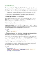
agent table could be further improved by moving all data about operations to
another table. Figure 11.3 shows a special diagram called an Entity Relationship
diagram, which illustrates the relationships between these tables.
An Entity Relationship diagram (ER diagram) reveals the relationships between
data elements. In this situation, I thought carefully about the data in the
spy
database. As I thought about the data, three distinct entities emerged. By sepa-
rating the
operation data from the agent data, I have removed redundancy: The
user enters operational data only one time. This eliminates several of the prob-
lems in the original database. It also fixes the situation where an operation’s
data was lost because a spy turned out to be a double agent. (I’m still bitter about
that defection.)
Third Normal Form: Ensure Functional Dependency
The third normal form concentrates on the elements associated with each entity.
For a table to be in the third normal form, that table must have a single primary
key and every field in the table must relate only to that key. For example, the
description field is a description of the
operation,
not the
agent,
so it belongs in
the
operation table.
In the third phase of normalization you look through each piece of table data
and ensure that it directly relates to the table in which it’s placed. If not, either
move it to a more appropriate table or build a new table for it.
365
C
h
a
p
t
e
r
1
1
D
a
t
a
N
o
r
m
a
l
i
z
a
t
i
o
n
FIGURE 11.3
A basic entity-
relationship
diagram for the
spy database.
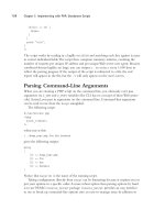
Defining Relationship Types
The easiest way to normalize your databases is with a stylized view of them such
as the ER diagram. ER diagrams are commonly used as a data-design tool. Take
another look at the ER diagram for the spy database in Figure 11.4.
This diagram illustrates the three entities in the
spy database (at least up to now)
and the relationships between them. Each entity is enclosed in a rectangle, and
the lines between each represent the relationships between the entities. Take a
careful look at the relationship lines. They have crow’s feet on them to indicate
some special relationship characteristics. There are essentially three kinds of
relationships (at least in this overview of data modeling).
Recognizing One-to-One Relationships
One-to-one relationships happen when each instance of entity A has exactly one
instance of entity B. A one-to-one entity is described as a simple line between two
entities with no special symbols on either end.
366
P
H
P
5
/M
y
S
Q
L
P
r
o
g
r
a
m
m
i
n
g
f
o
r
t
h
e
A
b
s
o
l
u
t
e
B
e
g
i
n
n
e
r
IN THE REAL WORLD
You might notice that my database fell into third normal form automatically
when I put it in second normal form. This is not unusual for very small data-
bases, but rare with the large complex databases used to describe real-world
enterprises. Even if your database seems to be in the third normal form already,
go through each field to see if it relates directly to its table.
FIGURE 11.4
The entity-
relationship
diagram for the
spy database.
One-to-one relationships are rare, because if the two entities are that closely
related, usually they can be combined into one table without any penalty. The spy
ER diagram in Figure 11.4 has no one-to-one relationships.
Describing Many-to-One Relationships
One-to-many (and many-to-one) relationships happen when one entity can con-
tain more than one instance of the other. For example, each operation can have
many spies, but in this example each agent can only be assigned to one mission
at a time. Thus the agent-to-operation relationship is considered a many-to-one
relationship, because a spy can have only one operation, but one operation can
relate to many agents. In this version of ER notation, I’m using crow’s feet to indi-
cate the many sides of the relationship.
There are actually several different kinds of one-to-many relationships, each with
a different use and symbol. For this overview I treat them all the same and use the
generic crow’s feet symbol. When you start writing more-involved databases,
investigate data diagramming more closely by looking into books on data normal-
ization and software engineering. Likewise, data normalization is a far more
involved topic than the brief discussion in this introductory book.
Recognizing Many-to-Many Relationships
The final type of relationship shown in the spy ER diagram is a many-to-many
relationship. This type of relationship occurs when each entity can have many
instances of the other. Agents and skills have this type of relationship, because
one agent can have any number of skills, and each skill can be used by any num-
ber of agents. A many-to-many relationship is usually shown by crow’s feet on
each end of the connecting line.
It’s important to generate an ER diagram of your data including the relationship
types, because different strategies for each type of relationship creation exist.
These strategies emerge as I build the SQL for the improved
spy database.
Building Your Data Tables
After designing the data according to the rules of normalization, you are ready
to build sample data tables in SQL. It pays to build your tables carefully to avoid
problems. I prefer to build all my tables in an SQL script so I can easily rebuild
my database if (okay, when) my programs mess up the data structure. Besides,
enemy agents are always lurking about preparing to sabotage my operations.
TRICK
TRICK
367
C
h
a
p
t
e
r
1
1
D
a
t
a
N
o
r
m
a
l
i
z
a
t
i
o
n