PATTERNS OF DATA MODELING- P41 pdf
Bạn đang xem bản rút gọn của tài liệu. Xem và tải ngay bản đầy đủ của tài liệu tại đây (159.91 KB, 5 trang )
14.2 Diagram Subject Area 187
14.2 Diagram Subject Area
A generic diagram is a picture that conveys the meaning of the underlying model. Figure
14.3 and Figure 14.4 support discrete tabs for attaching lines. The gray shading is for entity
types that involve metadata.
An Icon is a picture that is symbolic of something. Examples of Icons include an oval in
a data flow diagram and a compressor symbol in an equipment flow diagram. Each Icon has
a name, as well as a scale and position that are applied to its corresponding IconType. For ex-
ample, Figure 14.2 has two Icons for heat exchangers (IconTypes). One Icon is named “Evap-
orator” and the other Icon is named “Condenser”. Each Icon belongs to a specific Diagram.
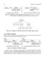
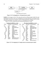
Figure 14.1 Example: Data flow diagram for designing a database (no ports).
reqmts
prepare
reqmts
UML
UML
model
prepare
IDEF1X
IDEF1X
model
generate
SQL
DDL
SQL
DDL
SQL
design database
model model
DDL
Figure 14.2 Example: Equipment flow diagram for an air conditioner (with ports).
E1:Expansion valve
C1:Compressor
CondenserEvaporator
refrigerant
outside air
tube
out
tube
in
tube
in
tube
out
warm air cool air
inout
in out
188 Chapter 14 / Generic Diagrams
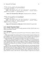
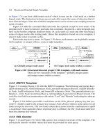
Figure 14.3 Diagram subject area, with tabs: UML model. A generic diagram
is a picture that suggests the meaning of the underlying model.
Icon
name {unique}
Diagram
name
1
*
scale
position
IconType
DiagramType
*
Tab
name
scale
position
1
*
Line
11source target
TabType
1
*
LineType
1
*
1
1
*
*
1
1
*
0 10 1
Figure 14.4 Diagram subject area, with tabs: IDEF1X model.
iconID
Icon
iconName (AK1.1)
scale
position
iconTypeID
IconType
. . .
diagramID
Diagram
diagramName
diagramTypeID (FK)
iconTypeID (FK)
diagramID (FK)
diagramTypeID
DiagramType
. . .
tabID
Tab
tabName
scale
position
iconID (FK)
tabTypeID (FK)
lineID
Line
lineTypeID (FK)
diagramID (FK)
sourceTabID (FK) (AK1.1)
targetTabID (FK) (AK2.1)
tabTypeID
TabType
. . .
lineTypeID
LineType
. . .
14.3 Model Subject Area 189
A Tab is a discrete position on an Icon for attaching a Line. A Tab has a name, as well
as a scale and position that are applied to its corresponding TabType. The relationships be-
tween Tab and Line illustrate the Node–Edge directed graph (see Chapter 3). The relation-
ships between Icon, IconType, Ta b, and TabType form a homomorphism (see Chapter 5).
A Line is a means for coupling two Tabs. A Diagram is a set of Icons and Lines. Section
14.5 defines DiagramType, IconType, Tab Type, and LineType.
Figure 14.5 and Figure 14.6 forego Tabs and permit lines to connect anywhere on an
Icon.
14.3 Model Subject Area
A semantic diagram has a model that expresses the meaning. Figure 14.7 and Figure 14.8
show the model with discrete ports.
Figure 14.5 Diagram subject area, no tabs: UML model.
Icon
name {unique}
Diagram
name
1
*
scale
position
IconType
DiagramType
*
Line
11
**
source target
LineType
1
*
1
1
*
*
1
iconTypeID
IconType
. . .
Figure 14.6 Diagram subject area, no tabs: IDEF1X model.
iconID
Icon
iconName (AK1.1)
scale
position
diagramID
Diagram
diagramName
diagramTypeID (FK)
iconTypeID (FK)
diagramID (FK)
lineID
Line
lineTypeID (FK)
diagramID (FK)
sourceIconID (FK)
targetIconID (FK)
lineTypeID
LineType
. . .
diagramTypeID
DiagramType
. . .
190 Chapter 14 / Generic Diagrams
Figure 14.7 Model subject area, with ports: UML model. A semantic
diagram has an underlying model that expresses the meaning.
Entity
name
EntityType
name {unique}
*
1
SimpleEntityExpandableEntity
PortType
name {unique}
1
*
Port
name
*
1
1
*
Model
1
*
1
*
Connection
0 1
0 1
1
1
input
output
ExpansionMapping
1
*
1
*
inner outer11
0 1
0 1
subModel
name
Figure 14.8 Model subject area, with ports: IDEF1X model.
entityDiscrim
entityID
Entity
entityName
entityDiscrim
entityTypeID (FK)
ExpandableEntity
expandableEntityID (FK)
submodelID (FK)
SimpleEntity
simpleEntityID (FK)
entityTypeID
EntityType
entityTypeName (AK1.1)
portTypeID
PortType
portTypeName (AK1.1)
entityTypeID (FK)
modelID (FK)
portID
Port
portName
portTypeID (FK)
entityID (FK)
connectionID
Connection
modelID (FK)
inputPortID (FK) (AK1.1)
outputPortID (FK) (AK2.1)
expansionMappingID
ExpansionMapping
expandableEntityID (FK)
innerPortID (FK) (AK1.1)
outerPortID (FK) (AK2.1)
modelID
Model
modelName
14.3 Model Subject Area 191
An Entity is a thing with semantic meaning. Examples of Entities include a data flow in
a data flow diagram and a piece of equipment in an equipment flow diagram. An Entity can
be represented by an Icon in a generic diagram. An Entity name may or may not be unique
within a model.
A Port is a defined place for an Entity, available for a connection. Just as Icons have
Ta bs , so too Entities have Ports. For example, an expansion valve has inlet and outlet ports.
An Entity has many Ports and each Por t belongs to a specific Entity.
An Entity may have multiple Ports with the same name. For example, a piping tee has
two outputs that are interchangeable (and consequently have the same name). A minimum
value function could have up to ten inputs and one output that is the minimum value.
Ports are helpful for some kinds of models and unnecessary for others. If a diagram
omits Ports , then connections go directly to Entities.
An EntityType is a classification of Entities. For example, E101 (an Entity) is a heat ex-
changer (an EntityType). The EntityType specifies the kinds of ports (PortType) that apply.
It would be clumsy to define ports individually. It is better to define them for an Entity-
Type. Thus, an EntityType can have PortTypes. A PortType is a classification of Ports. Each
PortTy p e belongs to a specific EntityType. Then each Entity defines Ports corresponding to
the PortTypes for its EntityType. Such a mechanism enforces uniformity. Note that the rela-
tionships among Entity, EntityType, Port, and PortType form a homomorphism (see Chapter
5).
A Model is a set of Entities and Connections and has a meaning that a diagram illus-
trates. Each Entity and Connection belong to a single Model. Some of the Entities in a Model
are ExpandableEntities and lead to submodels. Hence Models can be structured as a hierar-
chy of arbitrary depth.
There are two kinds of Entities: ExpandableEntities and SimpleEntities. An Expand-
ableEntity provides a placeholder for a submodel. In an implementation, double clicking the
corresponding icon leads to the expansion into a lower-level diagram. As Figure 14.1 illus-
trates, some Entities can be expanded into submodels with a finer level of detail. A submodel
is reusable and can be embedded in multiple places. A SimpleEntity encompasses all other
Entities that do not lead to a submodel.
A Connection is a binding between an input Port and an output Port. A Port may, or
may not, have a Connection. The various Connections establish the direction of flow through
Ports . Port and Connection illustrate the Node–Edge directed graph (see Chapter 3).
The ExpansionMapping takes a Po rt on an interface (outer Port for an ExpandableEn-
tity) and couples it to a Port (an inner Port) within the corresponding subModel. A Po rt may
participate in one ExpansionMapping as an inner Port, one ExpansionMapping as an outer
Port, or in no ExpansionMapping at all. The inner Port must belong to an Entity that is di-
rectly contained within the subModel.
Figure 14.9 and Figure 14.10 simplify the Model subject area and permit Connections
anywhere on an Entity.