Internetworking with TCP/IP- P41 docx
Bạn đang xem bản rút gọn của tài liệu. Xem và tải ngay bản đầy đủ của tài liệu tại đây (497.99 KB, 10 trang )
Sec.
18.8
ATM Adaptation
Layers
DEVICE DRIVER
5
sofrware in
t
host computer
host interface
-
board
optical fiber
I
1
1
I
ADAPTATION LAYER
1
t
CELL TRANSPORT
1
t
OPTICAL COMM.
4
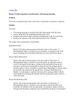
Figure
18.6
The conceptual organization of
ATM
interface hardware and the
flow of data through it. Software on a host interacts with an
adaptation layer protocol to send and receive data; the adaptation
layer converts to and from cells.
v
When establishing a connection, a host must spec@ which adaptation layer proto-
col to use. Both ends of the connection must agree on the choice, and the adaptation
layer cannot
be
changed once the connection has been established. To summarize:
-
Although ATM hardware uses small, jixed-size cells to transport data,
a higher layer protocol called an ATM Adaptation Layer provides
data transfer services for computers that use ATM. When a virtual
circuit is created, both ends of the circuit
must agree on which adup-
tation layer protocol will be used.
TCPlIP
Over
ATM
Networks
Chap.
18
18.9
ATM Adaptation Layer
5
Computers use
ATM
Adaptation
Layer
5
(AAL.5)
to send data across an
ATM
net-
work. Interestingly, although
ATM
uses small fmed-size cells at the lowest level,
AAL5
presents an interface that accepts and delivers large, variable-length packets.
Thus, the interface computers use to send data makes
ATM
appear much like a connec-
tionless technology. In particular,
AAL5
allows each packet to contain between
1
and
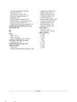
65,535 octets of data. Figure 18.7 illustrates the packet format that AAL5 uses.
Between
1
and
65,535
octets
of
data
&octet
trailer
Figure
18.7
(a) The basic packet format that
AAL5
accepts and delivers, and
(b)
the fields
in
the 8-octet
trailer
that follows the data.
&BIT
UU
Unlike most network frames that place control information in a header, -5
places control information in an 8-octet trailer at the end of the packet. The AAL5
trailer contains a 16-bit length field, a 32-bit cyclic redundancy check
(CRC)
used
as
a
frame checksum, and two 8-bit fields labeled
UU
and
CPZ
that are currently unused?.
Each
AALS
packet must be divided into cells for transport across
an
ATM
net-
work, and then must
be
recombined to form a packet before being delivered to the
re-
ceiving host. If the packet, including the 8-octet trailer, is
an
exact multiple of 48 oc-
tets, the division will produce completely full cells. If the packet is not an exact multi-
ple of 48 octets, the final cell will not be full. To accommodate arbitrary length pack-
ets, AALS allows the final cell to contain between
0
and
40
octets of
data,
followed by
zero padding, followed by the 8-octet trailer.
In
other words,
AALS
places the trailer
in
the last 8 octets of the final cell, where it can be found and extracted without knowing
the length of the packet.
tField
UU
can contain any value; field
CPI
must
be
set to zero.
&BIT
CPI
16-BIT
LENGTH
32-BIT
FRAME CHECKSUM
Sec.
18.10
AALS
Convergence, Segmentation, And Reassembly
36
1
18.1
0
AAL5 Convergence, Segmentation, And Reassembly
When an application sends data over an ATM connection using
-5,
the host
delivers a block of data to the
AAL5
interface.
AAL5
generates a trailer, divides the in-
formation into 48-octet pieces, and transfers each piece across the ATM network in a
single cell.
On
the receiving end of the connection,
AAL5
reassembles incoming cells
into a packet, checks the CRC to ensure that
all
pieces arrived correctly, and passes the
resulting block of data to the host software. The process of dividing a block of data
into cells and regrouping them is known as
ATM segmentation and reassemblyt
(SAR).
By separating the functions of segmentation and reassembly from cell transport,
AAL5
follows the layering principle. The ATM cell transfer layer is classified as
machine-to-machine
because the layering principle applies from one machine to the next
(e.g., between a host and a switch or between two switches). The
AAL5
layer is classi-
fied as
end-to-end
because the layering principle applies from the source to the destina-
tion
-
AAL5
presents the receiving software with data in exactly the same size blocks
as
the application passed to
AAL5
on the sending end.
How does
AAL5
on the receiving side know how many cells comprise a packet?
The sending
AAL5
uses the low-order bit of the
PAYLOAD
TYPE
field of the ATM cell
header to mark the final cell in a packet. One can think of it as
an
end-of-packet bit.
Thus, the receiving
AAL5
collects incoming cells until it finds one with the end-of-
packet bit set. ATM standards use the term
convergence
to describe mechanisms that
recognize the end of a packet. Although
AAL5
uses a single bit in the cell header for
convergence, other ATM adaptation layer protocols are
free
to use other convergence
mechanisms.
To summarize:
A
computer uses ATM Adaptation Layer
5
to transfer a large block of
data over an ATM virtual circuit. On the sending host,
AAL5
gen-
erates a trailer, segments the block of data into cells,
and
transmits
each cell over the virtual circuit. On the receiving host,
AALS
reassembles the cells to reproduce the original block of data, strips
off the trailer, and delivers the block of data to the receiving host
sofrware.
A
single bit in the cell header marks the final cell of a
given data block
18.1
1
Datagram Encapsulation And IP
MTU
Size
We said that
IP
uses
AAL5
to transfer datagrams across an ATM network. Before
data can be sent, a virtual circuit (PVC or SVC) must be in place to the destination
computer and
both
ends must agree to use
AAL5
on the circuit. To transfer a datagram,
the sender passes it to
AAL5
along with the VPWCI identifying the circuit.
AAL5
generates a trailer, divides the datagram into cells, and transfers the cells across the net-
tUse of the
term
reassembly
suggests
the
strong similarity between
AALS
segmentation and
IP
fragmen-
tation:
both
mechanisms divide
a
large block of
data
into
smaller units for transfer.
362
TCPIIP Over
ATM
Networks Chap. 18
work. At the receiving end,
AAL5
reassembles the cells, checks the
CRC
to verify that
no bits were lost or corrupted, extracts the datagram, and passes it to
IP.
In reality,
AALS
uses a 16-bit length field, making it possible to send
64K
octets
in a single packet. Despite the capabilities of
AAL5,
TCPm restricts the size of da-
tagrams that can
be
sent over ATM. The standards impose a default of 9180 octets? per
datagram. As with any network interface, when an outgoing datagram is larger than the
network MTU,
IP
fragments the datagram, and passes each fragment to
AAL5.
Thus,
AAL5
accepts, transfers, and delivers datagrams of 9180 octets or less. To summarize:
When TCP/IP sends data across an ATM network, it transfers an en-
tire datagram using ATM Adaptation Layer
5.
Although
AAL.5
can
accept and transfer packets that contain up to
64K
octets, the TCPnP
standards specify a default MTU of 9180 octets. IP must fragment
any datagram larger than 9180 octets before passing it to
AALS.
18.1
2
Packet
Type
And
Multiplexing
Observant readers will have noticed that the
AAL5
trailer does not include a
type
field. Thus, an
AAL5
frame is not self-identifying. As a result, the simplest form of
encapsulation described above does not suffice if the two ends want to send more than
one type of data across a single
VC
(e.g., packets other than
IP).
Two possibilities ex-
ist:
The two computers at the ends of a virtual circuit agree
a priori
that the cir-
cuit will
be
used for a specific protocol (e.g., the circuit will only
be
used to
send
IP
datagram).
The two computers at the ends of a virtual circuit agree
a priori
that some
octets of the data area will
be
reserved for use as a type field.
The former scheme, in which the computers agree on the high-level protocol for a
given circuit, has the advantage of not requiring additional information in a packet. For
example,
if
the computers agree to transfer
IP,
a sender can pass each datagram directly
to
AAL5
to transfer; nothing needs to
be
sent besides the datagram and the
AAL5
trailer. The chief disadvantage of such a scheme lies in duplication of virtual circuits: a
computer must create a separate virtual circuit for each high-level protocol. Because
most carriers charge for each virtual circuit, customers
try
to avoid using multiple cir-
cuits because it adds unnecessary cost.
The latter scheme, in which two computers use a single virtual circuit for multiple
protocols, has the advantage of allowing all traffic to travel over the same circuit, but
the disadvantage of requiring each packet to contain octets that
identlfy the protocol
type. The scheme also has the disadvantage that packets from
all
protocols travel with
the same delay and priority.
tThe size 9180 was chosen to make
ATM
compatible with an older technology called
Switched Multime-
gabit Data Service (SMDS);
a
value other than 9180 can
be
used if both ends agree.
Sec. 18.12 Packet Type And Multiplexing
363
The TCPIIP standards spec@ that computers can choose between the two methods
of using
AALS.
Both the sender and receiver must agree on how the circuit will be
used; the agreement may involve manual configuration. Furthermore, the standards
suggest that when computers choose to include
type
information in the packet, they
should use
a
standard
IEEE
802.2
Logical Link Control
(LLC)
header followed by a
SubNetwork Attachment Point (SNAP)
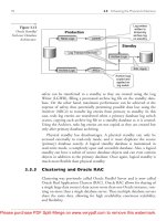
header. Figure
18.8
illustrates the LLCISNAP
information prefured to a datagram before it is sent over an ATM virtual circuit.
LLC
(
AA.
AA.
03)
I
OUI,
(00)
OUln
(00.00)
I
TYPE
(08.00)
IP
DATAGRAM
Figure
18.8
The packet format used to send a datagram over
AALS
when
multiplexing multiple protocols on a single
virtual
circuit.
The
I-octet
LLCISNAP
header identifies the contents as
an
IP
da-
tagram.
As the figure shows, the
LLC
field consists of three octets that contain the hexade-
cimal values
AA.AA.03t.
The SNAP header consists of five octets: three that contain
an
Organizationally Unique Identifier (OUI)
and two for a
type*.
Field
OUI
identifies
an organization that administers values in the
TYPE
field, and the
TYPE
field identifies
the packet
type.
For an IP datagram, the
OUI
field contains
00.00.00
to identify the or-
ganization responsible for Ethernet standards, and the
TYPE
field contains
08.00,
the
value used when encapsulating
IP
in an Ethernet frame. Software on the sending host
must prefix the LLCISNAP header to each packet before sending it to AALS, and
software on the receiving host must examine the header to determine how to handle the
packet.
18.13
IP Address Binding In An ATM Network
We have seen that encapsulating a datagram for transmission across an ATM net-
work is straightforward. By contrast,
IP
address binding in a Non-Broadcast Multiple-
Access
(NBUA)
environment can be difficult. Like other network technologies, ATM
assigns each attached computer a physical address that must be used when establishing
a virtual circuit.
On
one hand, because an ATM physical address is larger than an
IP
address, an ATM physical address cannot be encoded within an
IP
address. Thus,
IP
cannot use static address binding for ATM networks.
On
the other hand, ATM
?The notation represents each octet as a hexadecimal value separated
by
decimal points.
$To avoid unnecessary fragmentation, the eight octets of
an
LLCISNAP header
are
ignored
in
the
MTU
computation (i.e., the effective
MTU
of
an
ATM
connection that uses
an
LLCISNAP header is 9188).
364
TCPlIP
Over
ATM
Networks
Chap.
18
hardware does not support broadcast. Thus,
IP
cannot use conventional
ARP
to bind
addresses on
ATM
networks.
ATM
permanent virtual circuits further complicate address binding. Because a
manager configures each permanent virtual circuit manually, a host only knows the
circuit's VPWCI pair. Software on the host may not know the
IP
address nor the
ATM
hardware address of the remote endpoint.
Thus, an
IP
address binding mechan-
ism must provide for the identification of a remote computer connected over a PVC as
well
as
the dynamic creation of SVCs to known destinations.
Switched connection-oriented technologies further complicate address binding
be-
cause they require two levels of binding. First, when creating a virtual circuit over
which datagrams will
be
sent, the
IP
address of the destination must
be
mapped to an
ATM
endpoint address. The endpoint address is used to create a virtual circuit.
Second, when sending a datagram to a remote computer over an existing virtual circuit,
the destination's
IP
address must
be
mapped to the VPWCI pair for the circuit. The
second binding is used each time a datagram is sent over an
ATM
network; the first
binding is necessary only when a host creates an SVC.
18.14
Logical
IP
Subnet Concept
Although no protocol has been proposed to solve the general case of address bind-
ing for
NBMA
networks like
ATM,
a protocol has been devised for a restricted form.
The restricted form arises when a group of computers uses an
ATM
network in place of
a single (usually local) physical network. The group forms
a
Logical
IP
Subnet
(LIS).
Multiple logical
IP
subnets can
be
defined among a set of computers that
all
attach to
the same
ATM
hardware network. For example, Figure
18.9
illustrates eight computers
attached to an
ATM
network divided into two LIS.
ATM
NETWORK
Figure
18.9
Eight computers attached to
an
ATM
network participating in
two Logical
IP
Subnets. Computers marked with a slash partici-
pate in one LIS, while computers marked with a circle partici-
pate
in
the other
LIS.
Sec.
18.14
Logical
IP
Subnet Concept
365
As the figure shows, all computers attach to the same physical ATM network.
Computers
A,
C,
D,
E,
and
F
participate in one LIS, while computers
B,
F,
G,
and
H
participate in another. Each logical IP subnet functions like a separate LAN. The com-
puters participating in an LIS establish virtual circuits among themselves to exchange
datagramst. Because each LIS fomls a conceptually separate network,
IP
applies the
standard rules for a physical network to each LIS. For example, all computers in an
LIS share a single
IP
network prefix, and that prefix differs from the prefixes used by
other logical subnets. Furthermore, although the computers in an LIS can choose a non-
standard MTU, all computers must use the same MTU on
all
virtual circuits that
comprise the LIS. Finally, despite the ATM hardware that provides potential connec-
tivity, a host in one LIS is forbidden from communicating directly with a host in anoth-
er LIS. Instead, all communication between logical subnets must proceed through a
router just
as
communication between two physical Ethemets proceeds through a router.
In
Figure
18.9,
for example, machine
F
represents an IP router because it participates in
both logical subnets.
To summarize:
TCP/IP allows a subset of computers attached to an ATM network to
operate like an independent
LAN.
Such a group is called a
Logical
IP
Subnet
(US);
computers in an LIS share a single IP network prefix.
A computer in an LIS can communicate directly with any other com-
puter in the same LIS, but is required to use a router when communi-
cating with a computer in another LIS.
18.1
5
Connection Management
Hosts must manage ATM virtual circuits carefully because creating a circuit takes
time and, for commercial ATM services, can incur additional economic cost. Thus, the
simplistic approach of creating a virtual circuit, sending one datagram, and then closing
the circuit is too expensive. Instead, a host must maintain a record of open circuits so
they can be reused.
Circuit management occurs in the network interface software below
IP.
When a
host needs to send a datagram, it uses conventional IP routing to find the appropriate
next-hop address,
N$,
and passes it along with the datagram to the network interface.
The network interface examines its table of open virtual circuits.
If
an open circuit ex-
ists to
N,
the host uses
AAL5
to send the datagram. Otherwise, before the host can
send the datagram, it must locate a computer with IP address
N,
create a circuit, and add
the circuit to its table.
The concept of logical IP subnets constrains
IP
routing. In a properly configured
routing table, the next-hop address for each destination must be a computer within the
same logical subnet as the sender. To understand the constraint, remember that each
LIS is designed to operate like a single LAN. The same constraint holds for a host at-
tThe
standard specifies the use of LLCISNAP encapsulation within
an
LIS.
$As usual, a next-hop address is
an
IP
address.
366
TCPlIP
Over ATM Networks
Chap.
18
tached to a LAN, namely, each next-hop address in the routing table must be a router
attached to the LAN.
One of the reasons for dividing computers into logical subnets arises from
hardware and software constraints. A host cannot maintain an arbitrarily large number
of open virtual circuits at the same time because each circuit requires resources in the
ATM hardware and in the operating system. Dividing computers into logical subnets
limits the maximum number of simultaneously open circuits to the number of comput-
ers in the LIS.
18.16
Address Binding Within An
LIS
When a host creates a virtual circuit to a computer in its LIS, the host must speclfy
an ATM hardware address for the destination. How can a host map a next-hop address
into an appropriate ATM hardware address? The host cannot broadcast a request to all
computers in the LIS because ATM does not offer hardware broadcast. Instead, it con-
tacts a server to obtain the mapping. Communication between the host and server uses
ATMARP,
a variant of the ARP protocol described in Chapter
5.
As with conventional ARP, a sender forms a request that includes the sender's
IP
and ATM hardware addresses as well as the
IP
address of a target for which the ATM
hardware address is needed. The sender then transmits the request to the
ATMARP
server
for the logical subnet.
If
the server knows the ATM hardware address, it sends
an
ATW reply.
Otherwise, the server sends a
negative ATUARP reply.
18.1
7
ATMARP Packet Format
Figure 18.10 illustrates the format of an ATMARP packet. As the figure shows,
ATMARP modifies the ARP packet format slightly. The major change involves addi-
tional address length fields to accommodate ATM addresses.
To appreciate the
changes, one must understand that multiple address forms have been proposed for
ATM, and that no single form appears to be the emerging standard.
Telephone com-
panies that offer public ATM networks use an &octet format where each address is an
ISDN telephone number defined by
ITU
standard document
E.164.
By contrast, the
ATM Forum? allows each computer attached to a private ATM network to be assigned
a 20-octet
Network Service Access Point (NSAP)
address. Thus, a two-level hierarchical
address may be needed that specifies an E.164 address for a remote site and an NSAP
address of a host on a local switch at the site.
To accommodate multiple address formats and a two-level hierarchy, an ATMARP
packet contains two length fields for each ATM address as well
as
a length field for
each protocol address. As Figure 18.10 shows, an ATMARP packet begins with fixed-
size fields that specify address lengths. The first two fields follow the same format as
conventional ARP. The field labeled
HARDWARE TYPE
contains the hexadecimal
TThe ATM Forum is a consortium of industrial members that recommends standards for private ATM
Sec.
18.17
ATMARP
Packet Format
367
value
0x0013
for
ATM,
and the field labeled
PROTOCOL TYPE
contains the hexade-
cimal value
0x0800
for
IP.
Because the address format of the sender and target can differ, each
ATM
address
requires a length field. Field
SEND HLEN
specifies the length of the sender's
ATM
ad-
dress, and field
SEND HLEN2
specifies the length of the sender's
ATM
subaddress.
Fields
TAR
HLEN
and
TAR
HLEN2
specify the lengths of the target's
ATM
address and
subaddress. Finally, fields
SEND PLEN
and
TAR
PLEN
speafy the lengths of the
sender's and target's protocol addresses.
Following the length fields
in
the header,
an
ATMARP
packet contains six ad-
dresses. The first three address fields contain the sender's
ATM
address,
ATM
subad-
dress, and protocol address. The last three fields contain the target's
ATM
address,
ATM
subaddress,
and
protocol address.
In
the example in Figure
18.10,
both the sender
and target subaddress length fields contain zero, and the packet does not contain octets
for subaddresses.
1
HARDWARE TYPE (0x0013)
1
PROTOCOL TYPE (0x0800)
1
I
SENDER'S ATM ADDRESS (octets 0-3)
I
SEND HLEN (20)
SEND PLEN (4)
I-
-
SENDER'S ATM ADDRESS (octets
4-7)
SENDER'S ATM ADDRESS (octets 8-1 1)
SENDER'S ATM ADDRESS (octets 12-1 5)
SENDER'S ATM ADDRESS (octets 16-1 9)
*
SEND HLEN2 (0)
TAR HLEN (20)
I
SENDER'S PROTOCOL ADDRESS
I
OPERATION
TAR HLEN2 (0) TAR PLEN (4)
TARGET'S ATM ADDRESS (octets
0-3)
TARGET'S ATM ADDRESS (octets
4-71
I
-
TARGET'S ATM ADDRESS (octets
8-1
1)
TARGET'S ATM ADDRESS (octets 12-15)
TARGET'S ATM ADDRESS (octets 16-1 9)
TARGET'S PROTOCOL ADDRESS
Figure
18.10
The format of
an
ATMARP packet when used with 20-octet
ATM addresses
such
as
those recommended
by
the ATM
Forum.
368 TCPlIP
Over
ATM
Networks
Chap.
18
18.17.1 Format Of ATM Address Length Fields
Because
ATMARP
is designed for use with either E.164 addresses or 20-octet
NSAP
addresses, fields that contain an
ATM
address length include a bit that specifies
the address format. Figure 18.11 illustrates how
ATMARP
encodes the address type
and length in an 8-bit field.
Figure
18.11 The encoding of
ATM
address type and length in an 8-bit field.
Bit
I
distinguishes the two types of
ATM
addresses.
0
1
2
3
4
5
6
7
A
single bit encodes the type of an
ATM
address because only two forms are
available.
If
bit
1
contains zero, the address is in the
NSAP
format recommended by
the
ATM
Forum.
If
bit
1
contains one, the address is
in
the E.164 format recommended
by the
ITU.
Because each
ATM
address length field in an
ATMARP
packet has the
form shown
in
Figure 18.11, a single packet can contain multiple types of
ATM
ad-
dresses.
18.17.2 Operation Codes Used With The ATMARP Protocol
I
I
I I I
LENGTH OF ADDRESS IN OCTETS
I
I
I I I
0
The packet format shown in Figure 18.10 is used to request an address binding, re-
ply to a request, or request an inverse address binding. When a computer sends an
AT-
MARP
packet, it must set the
OPERATION
field to specify the type of binding. The
table in Figure 18.12 shows the values that can be used in the
OPERATION
field, and
gives the meaning of each. The remainder of this section explains how the protocol
works.
TYPE
Code Meaning
1 ATMARP Request
2 ATMARP Reply
8 lnverse ATMARP Request
9
lnverse ATMARP Reply
10 ATMARP Negative Ack
Figure
18.12 The values that can appear in the
OPERATION
field of an
AT-
MAW
packet and their meanings. When possible, values have
been chosen to agree with the operation codes used in conven-
tional
ARP.