Hands-On Microsoft SQL Server 2008 Integration Services part 36 pot
Bạn đang xem bản rút gọn của tài liệu. Xem và tải ngay bản đầy đủ của tài liệu tại đây (350.13 KB, 10 trang )
328 Hands-On Microsoft SQL Server 2008 Integration Services
Review
Event Handlers are like subpackages that can respond to events occurring at run time,
and if properly designed and developed, they can let you have a good night’s sleep
most nights. In this exercise, you created simple event handlers for OnTaskFailed
and OnPostExecute events and have seen how these event handlers wake up on the
occurrence of these events and perform the work they are configured to perform. You
can create quite a complex event handler to perform alternative actions if a particular
event happens. However, you also need to be careful while using these event handlers,
as the events are flagged up to the parent container at the cost of CPU cycles, unless
you filter out the events not to be sent to parent container. Last, you can disable event
handlers during design and testing using the DisableEventHandlers property on the
objects on which the event handlers have been defined.
As a Data Source for Reporting Services Report
This is an excellent feature that allows you to use an SSIS package as a data source
inside a reporting services report. You will study about a DataReader Destination of
Data Flow task in Chapter 9 that can act as a data source for external applications. The
Data Reader Destination is not actually a destination to write data to some data store;
rather, it is an interface for ASP.NET applications to connect and read data from an
SSIS package. This feature is not enabled by default in Reporting Services, so you have
to enable it before using it. The following describes the steps you need to perform.
Enable SSIS as a Data Source
To enable SSIS as a data source, you need to configure two reporting services config
files—RSReportDesigner.Config and RSReportServer.Config files.
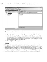
1. First, locate the RSReportDesigner.Config file, which exists in the C:\Program
Files\Microsoft Visual Studio 9.0\Common7\IDE\PrivateAssemblies folder in
a default installation.
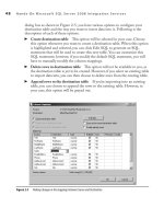
2. Open this file using either any text editor or Visual Studio 2008. The later
displays XML in a nice format that is easy to work with. Locate the Extensions
section and note that there are three different types of extensions—Render, Data,
and Designer extensions. SSIS being a data source, we will add the following
code in Data element as shown in Figure 8-15:
<Extension Name="SSIS"
Type="Microsoft.SqlServer.Dts.DtsClient.DtsConnection,Microsoft.SqlServer
.Dts.DtsClient, Version=10.0.0.0, Culture=neutral, PublicKeyToken=89845dcd808
0cc91"/>
Chapter 8: Advanced Features of Integration Services 329
3. And add the following code in the Designer element:
<Extension Name="SSIS"
Type="Microsoft.ReportingServices.QueryDesigners.
GenericQueryDesigner,Microsoft.ReportingServices.QueryDesigners"/>
4. Now locate and open the rsreportserver.config file, which should be located
in C:\Program Files\Microsoft SQL Server\MSRS10_50.MSSQLSERVER\
Reporting Services\ReportServer folder in a default installation. In the file locate
the Extensions section and add the following code in the Data element:
<Extension Name="SSIS" Type="Microsoft.SqlServer.Dts.DtsClient
.DtsConnection,Microsoft.SqlServer.Dts.DtsClient, Version=10.0.0.0,
Culture=neutral, PublicKeyToken=89845dcd8080cc91"/>
5. You may have to restart the Reporting Services service for the changes to
take effect.
Figure 8-15 Editing the RSReportDesigner.Config file
330 Hands-On Microsoft SQL Server 2008 Integration Services
Using SSIS as a Data Source
After you have enabled the SSRS to use SSIS as a data source, you can use this feature.
1. First you have to build an SSIS package in which your data flow task should
have DataReader Destination as a destination. The name you assign to the
DataReader Destination will be used in the Reporting Services, so keep it short.
In our example, I’m using the default name—DataReaderDest.
2. Now start a new reporting services project in BIDS and add a data source. In
the Type field, you will see SSIS listed as a data source. Select SSIS as shown in
Figure 8-16 and then add -f C:\SSIS\Packages\Sales.dtsx in the connection
string field. The SSRS data source will execute the package using DTEXEC
command and needs only the connection path in the connection string.
Figure 8-16 Using SSIS as a data source in the SSRS Report and specifying the connection path
Chapter 8: Advanced Features of Integration Services 331
3. Next add a report and select the data source created in the preceding step. Then
in the query field specify the name of the DataReader Destination, which in our
case is DataReaderDest as shown in Figure 8-17. You have done whatever was
required to use the SSIS DataReader Destination as a source in an SSRS report.
Now proceed to complete the report. When you run the report or preview it, you
will see data served at run time.
This method is easily configurable, though Microsoft does not recommend it. The
primary concern is the security settings, as the package runs under the Reporting
Services service account, which might be an issue in some situations. You need to
be careful when you deploy this method. However, this example is very useful in
demonstrating that the DataReader Destination can serve data dynamically to external
ASP.NET applications.
Figure 8-17 Specifying the DataReader Destination name in the Query String
332 Hands-On Microsoft SQL Server 2008 Integration Services
Summary
This was an absorbing chapter, as you’ve worked through various advanced features
provided in Integration Services to enhance the service quality of your packages.
You’ve worked with logging and log providers and have enabled logging for a package
in the Hands-On exercise. Then you worked with transactions and configured your
package to use transactions to handle three different kinds of scenarios for processing
transactional data. You also used checkpoints to restart your package from the point
of failure and learned about the effect of using transactions on checkpoints. Later in
the chapter you extended the Contacting Opportunities package to create personalized
e-mails using variables and property expressions. In the last Hands-On exercise,
you created event handlers in your package and saw how they become active when a
specified event happens.
With this chapter, you’ve concluded the workflow configurations of Integration
Services projects and their administration. In the next two chapters, you will learn
all about the data flow engine and how to transform data using Integration Services
Data Flow transformations. Until now, your packages did not include any data
flow or Data Flow tasks; however, from now on, we will focus mainly on data flow
components and their configurations and will not do much in the control flow. Note
that you cannot exclude control flow from your packages, as it must be part of an
Integration Services package.
Data Flow Components
Chapter 9
In This Chapter
c
From Control Flow to
Data Flow
c
Data Flow Component
Interfaces
c
Considerations for Bringing
Data into Data Flow
c
Data Flow Sources
c
Data Flow Transformations
c
Data Flow Destinations
c
Data Flow Paths
c
Summary
334 Hands-On Microsoft SQL Server 2008 Integration Services
I
ntegration Services provides several data-oriented services and the related
components that can be configured in the data flow task designer. The data
flow within a package extracts the data from a data source; performs the
transformations, computations, and derivations; and then loads the transformed data
to the data destination. The assembly used to represent a data flow is called a data
flow pipeline. The data flow engine of Integration Services is a data-driven execution
engine that provides a steady flow of data streams onto which atomic computations or
processes are applied.
The data flow constitutes three main components: data flow sources, data flow
transformations, and data flow destinations. Additionally, these components use data
flow paths to move the data from one component to the next in the data flow.
This chapter discusses the separation of data flow from the control flow and the
benefits thus achieved. It then discusses the data flow components consisting of data flow
sources, data flow transformations, data flow destinations, and data flow paths, plus the
inputs, outputs, error outputs, and the external columns to explain their functions. At the
end of the chapter, you will work through a Hands-On exercise to use these components.
From Control Flow to Data Flow
An Integration Services package relies on control flow and data flow as integral parts,
though other parts such as event handlers and log providers also support the package.
The data flow consists of three major components—data flow sources, data flow
transformations, and data flow destinations—which are connected via data flow paths.
One of the key enhancements in Integration Services over DTS 2000 is the separation
of control flow and data flow engines. The immediate predecessor to SSIS—i.e., SQL
Server 2000 Data Transformation Services—had all the control and data flow features
available in one engine and hence was difficult to use for creating complex packages to
meet some stringent data requirements. Integration Services introduces two engines,
called the integration services run-time engine and integration services data flow engine,
which separate data flow from control flow.
Inherently, the requirements of control flow and data flow are different for operational
and performance reasons. The requirements that drive the creation of an ETL package
are to extract data, perform some transformations, and load; when you get to the design
board, you realize that the package needs to populate variables along the way, wait for
data to be available that might be populated by some other part of the package, perform
operations in a particular order, move data from buffer to buffer, and so on. This order
of tasks, availability of data, and ability to move data as fast as possible from a buffer
to another buffer after applying transformations drive the designers in two opposing
directions—applying control to the package work flow and applying transformations
that are fast enough to the data flow. Although DTS 2000 fits the bill for tackling these
Chapter 9: Data Flow Components 335
operations, it lacks the ability to strike a perfect balance between control and data flow
requirements for the packages you design for various purposes.
The provision of a separate run-time engine and data flow engine provides better
control over packages and enhances the way the packages can be designed with separate
data flow. The run-time engine controls the order of the package workflow and provides
associated services, such as the ability to define an alternative workflow on the occurrence
of an event, to apply breakpoints on the tasks, to manage connections to the data sources,
to log data, and to manage transactions and variables. The data flow engine provides
high-performance data movement functionality, transformations optimized for speed,
and great extensibility by allowing you to create custom transformations on top of prebuilt
data sources, transformations, and destinations to load data capable of meeting most of
your requirements. You can include multiple data flow tasks in a package, with each data
flow task able to support multiple data sources, transformations, and destinations.
When you drop the Data Flow task on the Control Flow Designer surface,
you invoke the data flow engine. The Data Flow task is a special task provided in
Integration Services that allows you to create data movements and transformations
for data in a package. The Data Flow task replaces the DTS 2000 tasks, such as the
Data transformation task and the Data Driven Query task, which used to provide data
movement and manipulation functionalities. Unlike other tasks, double-clicking the
Data Flow task doesn’t invoke the Properties or Editor dialog box; instead, it opens
another designer surface represented by the Data Flow tab in BI Development Studio
(BIDS). The Data Flow task, accessed through the Data Flow tab, provides many
additional components such as data sources, transformations, and destinations to build
your data movement and transformation part of the package. The following section
covers the components available in the Data Flow tab.
Data Flow Component Interfaces
The Data Flow task consists of source and destination adapters that extract and load
data between heterogeneous data stores; transformations that modify, summarize,
cleanse, and extend data; and the paths that link these components together by
connecting output of one component to the input of the other component, thus
providing a sequence to the data flow. Some components accept multiple inputs and
can have multiple outputs. As mentioned, the Data Flow task can have multiple data
sources, transformations, and destinations. These components are designed for high
performance with a focus on data movement and manipulation efficiency.
All these components are available in the Toolbox window of the Data Flow tab
and can be added to the data flow just like control flow tasks. These components are
categorized in three ways: data flow sources, data flow transformations, and data flow
destinations. Data flow sources are used to extract data, data flow transformations help
336 Hands-On Microsoft SQL Server 2008 Integration Services
in modifying the extracted data, and this modified data is finally loaded into the data
silos using data flow destinations. While these components perform their functions,
they use data flow paths to move data from a source component to the destination
component. These data flow paths are similar to pipes in a pipeline. A data flow path
is quite interesting and helpful to debug and visualize the data. You can see the data
and metadata of the data flowing through data flow path using data viewers. Data flow
paths are covered in detail later in the chapter.
Each of the data flow components may have one or more inputs, outputs, or error
outputs associated with it. The data flow source reads the data from the external data
source, such as a flat file or a table of a relational database, using its external interface. It
then makes this data available to the downstream components. A data flow source uses
outputs to send the data in one or more columns via the data flow path to the inputs of
the transformations or destinations. A transformation receives data at its inputs and sends
data out at its outputs. Finally, a destination receives data at its inputs and sends data out
through its external interface to the destination. These components can optionally be
configured to have error outputs as well that can contain all the input columns and two
extra columns, one for error code and one for an error column to indicate the reason for
failure and the failing column. Let’s discuss these interfaces in detail.
External Metadata
This interface writes or reads data to and from external data stores (for example, an Excel
worksheet) and keeps a copy of their metadata. During design time, when you create a data
flow and add sources to your package, the metadata of the data from the sources is copied
to the external columns on data flow sources. Similarly, a data flow destination keeps a
copy of the destination metadata in its external columns as a snapshot of the destination
data store and compares the data schema with this snapshot before writing to the data
store. So, as the external columns keep a schema snapshot of the external data stores, they
help in the process of package validation. So if a data store is to be created at run time that
doesn’t exist at design time, or you make changes to a data store without updating the
package, you will get validation errors or warnings displayed by SSIS components. Some
of these warnings can be handled by using the ValidateExternalMetadata property on
the components, which works like DelayValidation property on the tasks and delays the
validation until the run time of the component.
Inputs
Inputs receive data from the data flow path in the input columns. The components
keep a copy of the metadata in the input interface as well, and the data received at
the inputs can be validated against the cached schema. You can configure an input
Chapter 9: Data Flow Components 337
to fail a component, ignore failure, or redirect a row in case it receives errors in
the input columns. In an Integration Services data flow, only the destinations and
transformations have inputs. You might think that as the data flow sources bring in
data to the data flow, they have inputs, but this is not the case. The data flow sources
use external columns to bring data into the data flow. Inputs and outputs (discussed
in the next section) are used when the data flows from one data flow component to
another data flow component. Whenever external data sources or storages are involved,
the data flows directly through the data flow sources or data flow destinations via the
external interface.
Outputs
The data is sent out from the outputs of the sources and transformations through the data
flow path to the inputs of the downstream components that could be transformations
or destinations. The output columns’ data can be validated against the external column
schema depending on the data flow components configurations. The output columns
are exposed in the Input and Output Properties tab of the Advanced Editor, where you
can configure them.
Error Outputs
When the data flows through the processing logic of the component, errors and mismatches
can occur. These errors could be related to the data type mismatch between the input
data and the corresponding metadata of an external column, or the data coming in may
be longer than the length defined in the corresponding external column. These kinds
of mismatches may cause data rows to raise errors or truncations. You can configure the
error handling in the component to fail the component on an error, ignore the error, or
redirect the failing rows to an error output. You can specify the error handling behavior
for each column using one of three options. Whenever the failing rows are redirected to
error output, two additional columns, ErrorColumn and ErrorCode, are also added to
indicate the failing column and the code of failure.
Considerations for Bringing Data into Data Flow
Integration Services uses the data flow engine to extract data from a data source,
transform and modify the data once it is in the data flow, and then load it to an external
data store. The data flow engine uses data flow sources for extracting data from a data
store. Figure 9-1 shows how the data is being extracted and parsed by a data source; it
also shows how an erroneous record will be handled.
In Figure 9-1, two records demonstrate how data flows through a data flow source.
As the data flow source reads the data from the external source, it translates the source