Hướng dẫn học Microsoft SQL Server 2008 part 88 ppt
Bạn đang xem bản rút gọn của tài liệu. Xem và tải ngay bản đầy đủ của tài liệu tại đây (717.07 KB, 10 trang )
Nielsen c37.tex V4 - 07/21/2009 2:13pm Page 832
Part V Data Connectivity
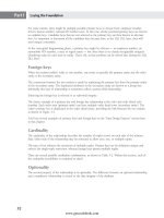
Unlike DTS, in which transformations happen in a single step as data is read from a source and written
to a destination, Integration Services enables several transformations to be used between reading and
writing data. Data flows can come from several sources, and they can be split and merged, and writ-
ten to several destinations within the confines of a single Data Flow task. Because the transformations
occur without reading and writing the database at every step, well-designed data flows can be surpris-
ingly fast.
FIGURE 37-2
The Data Flow tab of Integration Services’ design environment
Connection managers
A connection manager is a wrapper for the connection string and properties required to make a connec-
tion at runtime. Once the connection is defined, it can be referenced by other elements in the package
without duplicating the connection definition, thus simplifying the management of this information and
configuration for alternate environments.
Create a new connection manager by right-clicking in the Connection Managers pane or by choosing the
New option when configuring a task that requires a connection manager. When right-clicking, notice
that several of the more popular connection types are listed directly on the menu, but additional con-
nection types are available by choosing the New Connection option.
832
www.getcoolebook.com
Nielsen c37.tex V4 - 07/21/2009 2:13pm Page 833
Performing ETL with Integration Services 37
Each connection type has an editor dialog and properties that appear in the Properties pane, both of
which vary according to the connection type. Each of the two lists may contain properties not available
in the other. For example, the connection timeout can be set only in the OLE DB editor, while the delay
validation property must be set in the Properties pane.
Variables
As with all proper programming environments, Integration Services provides variables to control exe-
cution, pass around values, and so on. Right-click the design surface and choose Variables to show the
Variables pane. Notice that along with Name, Data Type, and Value columns, the Scope column indi-
cates at which level in the package hierarchy the variable is visible.
Variables with package scope (scope equals the package name) are visible everywhere, whereas variables
scoped to a task or event handler are visible only within that object. Variables scoped to a container are
visible to the container and any objects it contains.
By default, the Variables pane displays only variables whose scope matches the currently selected object
or one of its parents. For e xample, clicking on the design surface will select the package object and dis-
play only the variables scoped at the package level, but selecting a Control Flow task will show variables
for both the selected task and the package (the task’s parent). Alternately, the full variable list can be
displayed by selecting the Show All Variables button on the pane’s toolbar.
Create a new variable by first selecting the object to provide the scope and then click the Variable pane’s
Add Variable toolbar button. Once created, set the variable’s name, data type, and value. Note that you
cannot change a variable’s scope without deleting and recreating it.
In addition to scope, each variable has a namespace, which by default is either
User or System.
You can change the namespace for user-created variables, but there is very little that you can change
(only the occasional value) for system namespace variables. The namespace is used to fully qualify
a variable reference. For example, a variable called
MyVar in the user namespace is referred to as
@[User::MyVar].
Variable usage
Variable values can be manually set via the Variables pane, but their values can also come from a num-
ber of other sources, including the following:
■ Variable values can be provided at runtime via the
/SET switch on the dtexec utility (or
equivalent dialog of the
dtexecui utility).
■ Variable values can be entered as expressions, which are evaluated at runtime. Enter the
expression by clicking the Expression ellipses on the variable’s Properties pane, and
then use the Expression Builder to enter the appropriate formula. Be sure to set the
EvaluateAsExpression property to True to cause the contents of the variable to be
evaluated as a formula.
■
For and Foreach container tasks can set a variable to contain a simple numeric sequence,
each file in a directory on disk, each node in an XML document, and items from other lists
and collections.
■ Query results can provide variable values, either as an individual value or an entire result set.
■ Scripts can read and/or set variable values.
833
www.getcoolebook.com
Nielsen c37.tex V4 - 07/21/2009 2:13pm Page 834
Part V Data Connectivity
Among the many places for variables to be used, property e xpressions are one of the most useful, as
nearly any task property can be determined at runtime based on an expression. This enables variables to
control everything from the text of a query to the enabling/disabling of a task.
Expressions
Expressions are used throughout Integration Services to calculate values used in looping, splitting data
streams, setting variable values, and setting task properties. The language used to define an expression
is a totally new syntax, resembling a cross between C# and Transact-SQL. Fortunately, an Expression
Builder is available in many places where an expression can be entered. Some of the key themes include
the following:
■ Variables are referred to by prefixing them with an
@, and can be qualified by names-
pace, making
@[User::foo] the fully qualified reference to the user variable foo.
Columns are referred to by their name, and can be qualified by their source name, mak-
ing
[RawFileSource].[Customer Name]the fully qualified reference to the Customer
Name
column read from the RawFileSource. Square brackets are optional for names with
no embedded spaces or other special characters.
■ Operators are very C-like, including
== (double equal signs) for equality tests, prefix of an
exclamation mark for
not (for example, !> and !=), && for logical AND, || for logical OR,
and
? for conditional expressions (think IIf() function). For example, @[User::foo]
== 17 && CustomerID < 100
returns true if the variable foo equals 17 AND the
CustomerID column is less than 100.
■ String constants are enclosed in double quotes, and special characters are C-like backslash
escape sequences, such as
\n for new line and \t for tab.
■ The
cast operator works by describing the target type in parentheses immediately before
the value to be converted. For example,
(DT_I4)"193" will convert the string ‘‘193’’ to a
four-byte integer, whereas
(DT_STR,10,1252)@[User::foo]converts the value of the user
variable
foo to a 10-character string using codepage 1252. The codepage has no default, so
everyone will learn the number of their favorite codepage.
■ Functions mostly come from the Transact-SQL world, including the familiar date
(
GETDATE(), DATEADD(), YEAR()), string (SUBSTRING(), REPLACE(), LEN()),
and mathematical (
CEILING(), SIGN()) entries. Details do differ from standard T-SQL,
however, so use the Expression Builder or Books Online to check availability and syntax.
A codepage, not to be confused with a locale identifier, maps character representa-
tions to their corresponding codes. Two good sources for codepage references are
www.i18nguy.com/unicode/codepages.html and www.microsoft.com/typography/unicode/
cscp.htm
.
Configuring elements
A large number of elements work together in a functioning Integration Services package, including Con-
trol Flow tasks, task precedence, and data flow components. This section describes the concepts and
settings common to each area. Later, this chapter describes the functions and unique properties for indi-
vidual elements.
834
www.getcoolebook.com
Nielsen c37.tex V4 - 07/21/2009 2:13pm Page 835
Performing ETL with Integration Services 37
Control flow
Work flow for both the Control Flow and Event Handler tabs is configured by dragging control flow
elements (tasks and/or containers) onto the design surface, configuring each element’s properties, and
then setting execution order by connecting the items using precedence constraints. Each item can be
configured using the overlapping sets of properties in the Properties pane and the Editor dialog. Right-
click an item and choose Edit to invoke its Editor, which presents multiple pages (content varies accord-
ing to the type of task).
All editors include an Expressions page that enables many of the configurable properties to be specified
by expressions, rather than static values. You can view and modify existing expression assignments
directly on the page, or you can click the ellipses next to an expression to launch the Expression
Builder. You can add additional expression assignments by clicking the e llipses in the top line of the
expressions page, launching the Property Expressions Editor, shown in Figure 37-3. Choose the property
to be set in the left column, and then enter the expression in the right column, pressing the ellipses to
use the Expression Builder if desired.
FIGURE 37-3
Property Expressions Editor
While many of the properties available vary by item, several are available across all items, including
packages, containers, and individual tasks. These common properties include the following:
■ DelayValidation: Normally, each task in a package is validated before beginning execution
to avoid unnecessary partial runs (such as waiting 20 minutes to discover that the last step’s
filename was mistyped). Set this property to
true to delay validation until the task actually
runs. This option is useful for tasks that reference objects that don’t exist when the package
starts, but that will exist by the time the task executes.
■ Disable: When set to
true, the task will not execute. This option is also available from the
context menu’s Disable/Enable toggle. Note how disabled tasks display in a darker color.
835
www.getcoolebook.com
Nielsen c37.tex V4 - 07/21/2009 2:13pm Page 836
Part V Data Connectivity
■ DisableEventHandler: This keeps event handlers from executing for the current task,
although event handlers for parent objects (e.g., containers, packages) still execute.
■ Error handling properties are best considered as a group:
■ FailPackageOnFailure: When set to
true, the entire package fails when the individual
item fails. The default is
false.
■ FailParentOnFailure: When set to
true, the parent container fails when the individual
task fails. If a task is not explicitly included in a container (e.g.,
For Loop, Foreach
Loop
, or Sequence), then it is implicitly wrapped in an invisible TaskHost container,
which acts as the parent. The default i s
false.
■ MaximumErrorCount: Maximum number of errors a task or container can see before
failing itself. The default is 1, so the first error encountered will fail the task.
Because of the default settings that apply at the package, container, and task levels, any task
that fails will cause its container to fail, which in turn will fail the package, all based on the
MaximumErrorCount. This is true regardless of any failure branches defined by precedence
constraints. You can increase the
MaximumErrorCount on a task to allow error branching to
succeed.
Given this behavior, where do the ‘‘FailOn’’ properties fit in? Consider a container with
two tasks, one that is expected to fail in certain cases (call it ‘‘Try’’) and another that
will recover from the expected failure but is not itself expected to fail (call it ‘‘Recover’’).
The container’s
MaximumErrorCount must be increased to allow the ‘‘Recover’’ to be
reached when ‘‘Try’’ fails, but this has the side effect of ignoring failures in ‘‘Recover’’! Use the
FailPackageOnFailure property on ‘‘Recover’’ to stop the entire package when the task
fails, or
FailParentOnFailure to take the failure precedence branch from the container
when ‘‘Recover’’ fails.
■ LoggingMode: This property defaults to
UseParentSetting so that logging can be defined
for the entire package at once, but individual items can also be enabled or disabled.
■ Transactions can be used to ensure that a sequence of operations, such as changes to multi-
ple tables, either succeed or fail together. The following properties control transactions in a
package:
■ IsolationLevel: Specifies the isolation level of a transaction as one of the following:
Unspecified, Chaos, ReadUncommitted, ReadCommitted, RepeatableRead,
Serializable,orSnapshot . The default is Serializable.
■ TransactionOption: This property offers three options:
NotSupported (the item will
not participate in a transaction),
Supported (if a parent container requires a transaction,
then this item will participate), and
Required (if a parent container has not started a
transaction, then this container will start one).
Once begun by a parent container, all child items can participate in that transaction by
specifying a
TransactionOption setting of either Supported or Required.
Control flow precedence
As described earlier, precedence constraints determine the order in which tasks will execute. Select any
task or container to expose its precedence constraint arrow, and then drag that arrow to the task that
should follow it, repeating until all items are appropriately related. Any unconstrained task will be run
at the discretion of the runtime engine in an unpredictable and often parallel ordering. Each constraint
836
www.getcoolebook.com
Nielsen c37.tex V4 - 07/21/2009 2:13pm Page 837
Performing ETL with Integration Services 37
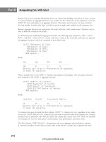
defaults to an ‘‘On Success’’ constraint, which can be adjusted by double-clicking the constraint to reveal
the Precedence Constraint Editor, shown in Figure 37-4.
FIGURE 37-4
Precedence Constraint Editor
The upper half of the editor, ‘‘Constraint options,’’ determines when the constraint should fire. It relies
on two evaluation operation concepts:
■ Constraint: How the previous item completed — Success, Failure, or Completion (Comple-
tion being any outcome, either success or failure)
■ Expression: The evaluation of the entered expression, which must resolve to either true or
false
These concepts are combined as four separate options — constraint, expression, expression and con-
straint, expression or constraint — enabling very flexible constraint construction. For example, consider
a task that processes a previously loaded table of data and counts the successfully processed rows. The
processing task could have two outgoing paths: a success path indicating that the task was successful
and that the processed rowcount matches the loaded rowcount, and a failure path indicating that either
the task failed or the rowcounts don’t match.
The lower half of the editor, labeled ‘‘Multiple constraints,’’ determines how the downstream tasks
should deal with multiple incoming arrows. If logical
AND is chosen (the default), then all the incoming
constraints must fire before the task can execute. If logical
OR is chosen, then any incoming constraint
firing will cause the task to execute. Logical
AND is the most frequently used behavior, but logical
837
www.getcoolebook.com
Nielsen c37.tex V4 - 07/21/2009 2:13pm Page 838
Part V Data Connectivity
OR is useful for work flows that split apart and then rejoin. For example, control can split when an
upstream task has b oth success and failure branches, but the failure branch needs to rejoin the normal
processing once the error has been resolved. Using a logical
AND at the merge point would require both
the success and the failure branches to execute before the next task could run, which cannot happen by
definition. Logical
AND constraints are presented visually as solid lines, whereas logical OR constraints
are dotted lines.
The arrows that represent precedence constraints provide other visual clues as to the type of constraint.
Green arrows denote a success constraint, red a failure constraint, and blue a completion constraint.
Constraints that use an expression include an f(x) icon. There is no visual queue to distinguish between
Constraint AND expression versus Constraint OR expression, so it is best to double-check
the Precedence Constraint Editor when an f(x) is displayed. For example, a green arrow with an f(x)
displayed could fire even if the preceding task had failed, given the expression had been satisfied and
the
Constraint OR expression option was chosen.
Data flow
Unlike other tasks that can be configured in the control flow, a Data Flow task does not show an Edi-
tor dialog i n response to an edit request. Instead, it switches to the Data Flow tab to view/configure the
task details. Each component appearing on the design surface can in turn be configured in the Prop-
erties pane, b y a component-specific editor dialog, and, for many components, by an advanced editor
as well.
Each data flow must begin with at least one Data Flow source, and generally ends with one or more
Data Flow destinations, providing a source and sink for the data processed within the task. Between
source and destination, any number of transformations may be configured to sort, convert, aggregate, or
otherwise change the data.
Out of each source or transformation, a green Data Flow path arrow is available to be connected to
the next component. Place the next component on the design surface and connect it to the path before
attempting to configure the new component, as the path provides necessary meta-data for configuration.
Follow a similar process for the red error flow for any component that has been configured to redirect
error rows.
Use the Data Flow Path Editor to view/configure paths as necessary, double-clicking on a path to invoke
its editor. The editor has three pages:
■ General: For name, description, and annotation options. While the default annotations are
usually adequate, c onsider enabling additional annotations for more complex flows with
intertwined paths.
■ Metadata: Displays metadata for each column in the Data Flow path, including data type and
source component. This information is read-only, so adjust upstream components as necessary
to make changes, or use a Data Conversion transformation to perform necessary conversions.
■ Data Viewers: Allows different types of Data Viewers to be attached to the path for testing
and debugging.
Because a data flow occurs within a single Control Flow task, any component that fails will cause the
task to fail.
838
www.getcoolebook.com
Nielsen c37.tex V4 - 07/21/2009 2:13pm Page 839
Performing ETL with Integration Services 37
Event handlers
Event handlers can be defined for a long list of possible events for any Control Flow task or container.
Use them for custom logging, error handling, common initialization code, and a variety of other tasks. If
a handler is not defined for a given item when an event fires, then Integration Services will search par-
ent containers up to the package level looking for a corresponding event handler to use instead. It is this
‘‘inheritance’’ that makes event handlers useful, enabling a single handler to be built once and then used
repeatedly over many tasks and containers.
To construct an event handler, switch to the Event Handlers tab and choose the Control Flow item
(Executable) in the upper-left drop-down list and the event in the upper-right list. Then click the
hotlink on the design surface to initialize the event. Build the logic within the handler as if it were just
another control flow.
Executing a package in development
As portions of a package are completed, they can be tested by running the package within the develop-
ment environment. Right-click a package in the Solution Explorer and c hoose Execute Package to start
the package i n debug mode. Packages run in debug mode display progress within the designer environ-
ment, with tasks and components changing from white (not yet run) to yellow (running) to green or red
(completed with success or failure, respectively).
There are other convenient methods for executing a package from within Business Intelli-
gence Development Studio, but you must ensure that the correct object executes. Select-
ing Start Debugging from the menu, keyboard (F5), or toolbar can be very convenient, but ensure that
the package to be executed has been ‘‘Set as Startup Object’’ by right-clicking on that package in the
Solution Explorer. In addition, solutions that contain more than one project may execute unexpected
actions (such as deploying an Analysis Services database) regardless of startup object/project settings
before beginning to debug the selected package. Even in development, inadvertently starting a six-hour
data load or stepping on a cube definition can be quite painful.
Once the debug run begins, an Execution Results tab appears displaying the execution trace, including
detailed messages and timing for each element of the package. When the package completes, it remains
in debug mode to enable variables and state information to be reviewed. To return to design mode,
choose the Stop button on the Debug toolbar, or choose Stop Debugging from the Debug menu
(Shift+F5).
You can set breakpoints on any task, container, or the package by right-clicking on the object and
selecting Edit Breakpoints. The Set Breakpoints dialog (see Figure 37-5) enables a breakpoint to be set
on any event associated with that object. PreExecute and PostExecute events are common choices; select-
ing an object and pressing F9 is a shortcut for toggling the PreExecute event breakpoint. Optionally,
instead of breaking at every execution (Always), a breakpoint can be ignored until the nth execution (Hit
count equals), any time at or after the nth execution (Hit count greater than or equal to), or ignored
except for the nth, 2nth, etc., execution (Hit count multiple).
While execution is suspended at a breakpoint, use the Locals window to view the current values of vari-
ables. You can also check the Output window for useful messages and warnings, and the Progress tab
for details on run history across all tasks.
The analogue to the breakpoint for data flows is the Data Viewer. Double-click on a data path of
interest to add a viewer. Then, during a debug run, package execution will be suspended when the Data
839
www.getcoolebook.com
Nielsen c37.tex V4 - 07/21/2009 2:13pm Page 840
Part V Data Connectivity
Viewer has been populated with data. Choose the Go or Detach buttons on the Data Viewer to resume
execution.
FIGURE 37-5
Set Breakpoints dialog
Breakpoints can also be placed in the code of a Script task. Open the script, set a breakpoint on the line
of interest, and Integration Services will stop in the script debugger at the appropriate place.
Integration Services Package Elements
This section describes in detail the individual elements that can be used in constructing an Integration
Services package. For general concepts and common properties, review the earlier sections of this
chapter.
Connection managers
A connection manager is a wrapper for the connection string and properties required to make a c onnec-
tion at runtime. Once the connection is defined, it can be referenced by other elements in the package
without duplicating the connection definition. This simplifies the management of this information and
configuration for alternate environments.
840
www.getcoolebook.com
Nielsen c37.tex V4 - 07/21/2009 2:13pm Page 841
Performing ETL with Integration Services 37
Database
Defining database connections through one of the available connection managers requires setting a few
key properties:
■ Provider: The driver to be used in accessing the database
■ Server: The server or filename containing the database to be accessed
■ Initial Catalog: The default database in a multi-database source
■ Security: Database authentication method and any username/password required
The first choice for accessing databases is generally an OLE DB connection manager using one of the
many native providers, including SQL Server, Oracle, Jet (Access), and a long list of other source types.
Other database connection managers include the following:
The key to most Integration Services packages is speed. ADO.NET has more capabilities,
but in most cases that is not what you are after. Most developers prefer OLE DB for that
reason.
■ ADO: Provides ADO abstractions (such as command, recordset) on top of the OLE DB
provider. ADO is not used by Integration Services built-in elements, but it could be required
by custom tasks written to the ADO i nterface.
■ ADO.NET: Provides ADO.NET abstractions (such as named parameters, data reader, data
set) for the selected database connection. While not as fast as using OLE DB, an ADO.NET
connection can execute complex parameterized scripts, provide an in-memory recordset to a
Foreach loop, or support custom tasks written using C# or VB.NET.
■ ODBC: Allows a connection manager to be configured based on an ODBC DSN. This is useful
when OLE DB or .NET providers are not available for a given source (e.g., Paradox).
■ OLE DB: The OLE DB connection manager is generally the preferred database connection
due to its raw speed. It provides methods for basic parameter substitution but falls short of
ADO.NET’s flexibility.
■ Analysis Services: When accessing an existing Analysis Services database, this connection
manager is equivalent to an OLE DB connection using the Analysis Services 10.0 provider.
Alternately, an Analysis Services database in the same solution can be referenced — a useful
feature for packages being developed in support of a new database. If one of the older OLAP
providers is needed for some reason, it can be accessed via the OLE DB connection manager.
■ SQL Server Mobile: Allows a connection to mobile database .
SDF files
As individual tasks execute, a connection described by the connection manager is opened and closed
for each task. This default setting safely isolates tasks, keeping prior tasks from tweaking the connection
of subsequent tasks. If you would like to keep the same connection between tasks, then set the
RetainSameConnection property to True. With appropriate care, this allows a session to be shared
between tasks for the manual control of transactions, the passing of temp tables, and so on.
File
Remember that every file or folder referenced needs to be available not only at design time, but
after a package is deployed as well. Consider using Universal Naming Convention (UNC) paths for
global information or package configurations (see ‘‘Maintainable Packages,’’ later in this chapter)
841
www.getcoolebook.com