Sổ tay tiêu chuẩn thiết kế máy P25 pptx
Bạn đang xem bản rút gọn của tài liệu. Xem và tải ngay bản đầy đủ của tài liệu tại đây (1022.5 KB, 38 trang )
CHAPTER
21
THREADED
FASTENERS
Joseph
E.
Shigley
Professor
Emeritus
The
University
of
Michigan
Ann
Arbor,
Michigan
21.1 SCREW
THREADS/21.1
21.2
BOLTS/21.5
21.3
SCREWS/21.11
21.4
NUTS/21.28
21.5 TAPPING SCREWS
/
21.35
REFERENCE/21.38
This chapter
is
intended
to
cover
the
description, uses, materials,
and
sizes
of
threaded fasteners.
The
amount
of
data available concerning this subject
is
extremely large,
so the
intent here
is to
provide
the
information necessary
for the
usual
machine-design task
of
selecting such fasteners.
The
data contained
in
this
chapter have been compiled
in
part
from
the
standards listed
in
Ref.
[21.1].
27,
T
SCREWTHREADS
Standard screw threads consist
of the
Unified
inch series
and the
metric
series.
Two
profiles
have been standardized
in the
metric series; these
are
called
the M and MJ
profiles.
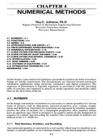
Figure
21.1
shows that both
the
Unified
and
metric
M
threads utilize
the
same profile.
The
metric
MJ
profile
has a
rounded
fillet
at the
root
of the
external thread
and
a
larger minor diameter
of
both
the
internal
and
external threads. This profile
is
used
for
applications requiring
a
high
fatigue
strength
and is
also employed
in
aerospace
applications.
The
Unified-series profile, shown
in
Fig. 21.1,
is
designated
as UN.
Another uni-
fied
profile, designated
as
UNR,
has a
rounded root
on the
external thread.
Unified
thread standards
are
based
on the
nominal size (major diameter)
and the
number
of
threads
per
inch.
The
three standards
coarse
(UNC), fine (UNF),
and
extra
fine
(UNEF)
are
listed
in
Table
21.1
and are
called
the
standard
series.
Typical
specifications
would
be
written
/4-20
UNC or
/4-20 UNRC
Both these designations
specify
a
nominal size
of
1
A
in and 20
threads
per
inch.
A
constant-pitch
unified
series consisting
of 4, 6,
8,12,16,
20, 28, and 32
threads
per
inch
has
also been standardized. These
are
used mostly
for
sizes over
1 in, and 8
UN,
12 UN, and 16 UN are the
preferred pitches.
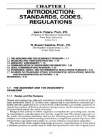
FIGURE
21.1
Basic thread profile
for
unified
(UN)
and
metric
(M)
threads
(ISO 68).
D(d)
=
basic major diameter
of
internal
(external)
thread;
D\(di)
=
basic minor
diameter
of
internal (external) thread;
D
2
(d
2
)
=
basic pitch diameter
of
internal (external)
thread;
p
=
pitch;#
=
0.5V3p.
As
shown
in
Table
21.2,
the
metric series consists
of a
coarse thread
and,
often,
several
fine
threads.These
are
specified
by
giving
the
size
or
major
diameter
and the
pitch
(see
Fig.
21.1).
Typical specifications would
be
written
M
70
x
1.5 or
MJ
7Ox
1.5
which
specifies
a
major
diameter
of 70 mm and a
pitch
of 1.5 mm.
Unified
threads
may be
further
designated
as UN A for
external threads
and UN
B for
internal threads.
The
tolerance classes
are
IA,
2A, and
3A
for
external threads
and
IB,
2B, and 3B for
internal threads. Class
2 is for
general use, class
3 is a
tight
fit
used
where great accuracy
is
required,
and
class
1 is a
loose
fit
which permits very
easy
assembly
and
allows
the
possibility
of
nicks
on the
threads.
Metric
threads utilize
the
international tolerance grades
(see
Chap.
19).
21.1.1
Choosing
the
Pitch
The
Unified coarse-thread series
(UNC
or
UNRC)
and the
metric coarse-thread
series
(M or MJ)
provide
the
most resistance
to
internal thread stripping. Conse-
quently,
coarse threads should
be
used
for
materials such
as
brass, cast iron,
alu-
minum,
and
other lower-strength materials. However,
the
coarse-thread series
are
TABLE
21.1
Standard Series
of UN and UNR
Screw
Threads*
Threads
per
inch
Nominal
Basic
major
Coarse, Fine,
Extra-fine,
size
diameter
UNC UNF
UNEF
0
0.0600
80
1
0.0730
64 72
2
0.0860
56 64
3
0.0990
48 56
4
0.1120
40 48
5
0.1250
40 44
6
0.1380
32 40
8
0.1640
32 36
10
0.1900
24 32
12
0.2160
24 28 32
i
0.2500
20 28 32
lk
0.3125
18 24 32
i
0.3750
16 24 32
&
0.4375
14 20 28
i
0.500
13 20 28
&
0.5625
12 18 24
J
0.6250
11
18 24
I'
0.7500
10 16 20
I
0.8750
9 14 20
1
.0000
8 12 20
It
.1250
7 12 18
11
.2500
7 12 18
Ii
.3750
6 12 18
Ii
.5000
6 12 18
fAIl
dimensions
in
inches.
TABLE
21.2
Standard Diameter-Pitch Combinations
for
Metric
M
Screw
Threads
1
Basic major diameter Pitch
Preferred
First option Second option Coarse Fine
1.6
0.35
2
0.4
2.5
0.45
3
0.5
3.5
0.6
4
0.7
5
0.8
6
1
TABLE
21.2
Standard Diameter-Pitch Combinations
for
Metric
M
Screw
Threads
1
(Continued)
Basic
major
diameter Pitch
Preferred
First option Second option Coarse Fine
8
1.25
10
1.5
.25
or
0.75
12
1.75
.25orl
14
2
.5orl.25t
15
16
2 .5
17
18
.5
20
2.5 .5 or 1
22
2.5§
.5
24
3 2
25
1.5
27
3f
2
30
3.5
2
or
0.5
33
2
35f
1.5
36
4 2
39
2
40
1.5
42
4.5 2
45
1.5
48
5 2
50
1.5
55
1.5
56
5.5 2
60
1.5
64
6 2
65
1.5
70
1.5
72
6 2
75
1.5
80
6 1.5
85
2
90
6 2
95
2
100
6 2
105
2
110
2
120
2
130
2
140
2
150
2
160
3
170
3
180
3
190
3
200
3
t
All
dimensions
in
millimeters.
JOnIy
for
engine spark plugs.
§Only
for
high-strength structural steel
bolts.
f
Only
for
nuts
for
bearings.
also widely used with other materials because mass-produced fasteners
are
usually
made with coarse threads
and
hence
are the
most economical.
The
coarse-thread
series should also
be
used whenever
fast
assembly
is
needed
or
when dropping
or
handling
the
fasteners
may
damage
the
threads
by
causing nicks
or
dents.
The
Unified fine-thread
series
(UNF
or
UNRF)
and
metric fine-thread series
(M
and MJ)
find
their greatest
use
where
a
high fastener strength
is
required
and
where
vibration
may be a
problem.
The
shallow depth
of
thread,
and
hence larger
minor diameter, increases
the
strength
of the
external member.
It
also permits
a
smaller wall thickness
for the
internal member.
Extra-fine-series screw threads
are
useful
for
thin nuts,
on
thin-wall tubing,
and
where
parts
may
require
a
very
fine
adjustment.
21.1.2
Pipe Threads
The
profile
of
pipe
threads
is
similar
to the UN
profile except that there
is a
taper
of
1 on 16
based
on the
outside diameter.
The
last
few
threads will
be
imperfect because
of
the
taper
and the
chamfer
on the
thread-cutting die. Table 21.3 gives
the
basic
dimensions
of
Unified-inch-series
standard pipe threads.
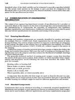
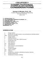
21.2 BOLTS
The
symbols used
to
indicate
the
dimensions
of
square
and hex
bolt heads
are
shown
in
Fig. 21.2.
See
Table 21.4
for
head dimensions.
The
washer
or
bearing
face
shown
in
Fig.
21.2b
is
standard
for the
heavy structural
hex
bolt (Table 21.4)
and for the fin-
ished
hex
bolt.
A
finished
hex
bolt
is
identical
to a hex cap
screw (see Table
21.13).
The
basic thread length
for
bolts
is
T2D
+
0.25
L<6
H2»
+
0.50
L>6
(21-D
TABLE
21.3
Basic
Dimensions
of
Standard
Pipe
Threads
1
Nominal
Outside
Threads
Thread
length
pipe
size
diameter
per
inch
on
OD
(approx.)
A
0.3125
27
0.261
i
0.405
27
0.264
i
0.540
18
0.402
i
0.675
18
0.408
i
0.840
14
0.534
i
1.050
14
0.546
1
1.315
Hi
0.683
Ii
1.660
Ul
0.707
Ii
1.900
Ul
0.723
2
2.375
Ul
0.757
2i
2.875
8
1.138
Over
2i 8
t
All
dimensions
in
inches.
FIGURE
21.2 Bolt
heads,
(a)
Square;
(b)
hex;
the
washer
or
bearing
face
is
used
only
on
heavy
hex
structural bolts.
where
L =
bolt length, measured under
the
head,
and
L
T
=
thread length,
in
inches.
Head dimensions
for
metric
hex
bolts
are
listed
in
Table 21.5.
The
heavy
hex
structural
bolt
is the
only
one of
these with
a
bearing
face.
The
thread length
is
{
2D + 6 L
<
125 D
<
48
2D + 12 125
<
L
<
200
(21.2)
2Z)
+ 25 L > 200
Here
L and
L
T
are in
millimeters.
Standards
for
bolt materials
and the
corresponding head markings
are
listed
in
Tables
21.6,21.7,
and
21.8.
The
property class number
in
Table 21.8
is a
code derived
from
the
tensile strength
S
ut
and the
yield strength
S
y
.
If we
designate
the
class num-
ber
by the
symbol
X.
Y,
then
X=
5^/100
and
Y=S
y
/S
ut
.
Bolts
in
metric sizes
are
nor-
mally
manufactured
to SAE and
ASTM specifications too.
For
fillet
dimensions,
see
Tables
21.9
and
21.10.
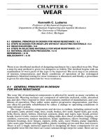
Typical
heads
for
round-head
or
carriage
bolts
are
shown
in
Fig. 21.3,
and
head
dimensions
are
given
in
Tables 21.11
and
21.12.
Other standard bolts
are
step bolts,
which
have
a
square neck with
a
larger-diameter head,
and
several countersunk-head
bolts with
and
without square necks.
The
bolts listed
in
Table 21.12
are the
only round-
head
metric bolts that
are
standardized
at
this writing. Round-head bolts
are
made
to
the
same material specifications
as hex
bolts
and use the
same head markings.
TABLE
21.4
Dimensions
of
Square-
and
Hex-Head Bolts (Inch
Series)
Head
type
Structural
Square
Regular
next
Heavy
next
hex
Nominal
I I
I I
size
WH WH
WHWH
i
i
tt
*
tt
4
i
a
i
*
j
ft i ft i
ft i a i
«
i
J
a
I
«
i M i
*
i
«
8 ti a
i*
8
IA
a
i
U
i U i
ii
i
it
ti
i
i*
«
IA
s
i*
a
IA
s
i
H
it
ii
a
U
a
ij
a
ii
Mt
J
Mt J 1«
I
Hi
«
Ii
Ii S
»i
i 2 fi 2 H
Ii
2*
3
2A
8
2*
S 2ft
S
4
2i
i
21
i
21
i
2j
tf
fAlso
available
in
standard
sizes
up to 4 in.
JAlso
available
in
standard
sizes
up to 3 in.
TABLE
21.5
Dimensions
of
Metric
Hex
Bolts (Metric
Series)
1
Type
of
bolt
Regular}:
Heavy Structural
Nominal
Thread
1
I
diameter
pitch
WHWHWH
M5
0.8 8
3.58
M6 1 10
4.38
M8
1.25
13
5.68
MlO
1.5 16
6.85
M12
1.75
18
7.95
21
7.95
M14
2 21
9.25
24
9.25
M16
2 24
10.75
27
10.75
27
10.75
M20
2.5 30
13.40
34
13.40
34
13.40
M22
2.5
36
14.90
M24
3 36
15.90
41
15.90
41
15.90
M27
3
46
17.90
M30 3.5 46
19.75
50
19.75
50
19.75
M36
4 55
23.55
60
23.55
60
23.55
fHead
dimensions
are
maximum.
AH
dimensions
in
millimeters.
JAlso
available
in
standard sizes
to 100 mm.
TABLE
21.6
SAE
Grade Markings
for
Steel Bolts
SAE
Size Proof Tensile
grade range
strength,!
strength,!
no.
incl.
kpsi kpsi Material
1
Hi
Low-or
medium-
carbon steel
2
H 55 74
4-Ii
33 60
5
4-1 85 120
Medium-carbon
steel,
Q&T
Ii-Ii
74 105
5.2
|-1
85 120
Low-carbon
martensite
steel,
Q&T
7
Hi 105 133
Medium-carbon
alloy
steel,
Q &
TJ
8
Hi 120 150
Medium-carbon
alloy
steel,
Q&T
8.2
i-1
120 150
Low-carbon
martensite
steel,
Q&T
fMinimum
values.
IRoIl
threaded
after
heat treatment.
SOURCES:
See
"Helpful
Hints,'*
by
Russell, Burdsall
&
Ward Corp., Mentor, Ohio 44060;
and
Chap.
23.
Head
marking
TABLE
21.7
ASTM
Grade
Markings
for
Steel
Bolts
Size Proof
Tensile
ASTNf
range
strength,!
strength,!
designation
incl.
kpsi kpsi Material
A307
J
to 4
Low-carbon
steel
A325
type
Jtol
85
120
Medium-carbon
steel,
I
Q&T
Ii
to
Ii
74 105
A32Stype
i
to 1 85 120
Low-carbon
martensite
2
steel,
Q&T
Ii
to
Ii
74 105
A325type
{ to 1 85 120
Weathering steel,
3
Q&T
Ii
to
Ii
74 105
A354
grade
Alloy
steel,
Q&T
BC
A354
grade
J
to
4 120 150
Alloy steel,
Q & T
BD
A449
Jtol
85 120
Medium-carbon
steel,
Q&T
Ii
to
Ii
74 105
Ij
to 3 55 90
A490type
itoli
120 150
Alloy
steel,
Q & T
1
A490
type Weathering steel,
3
Q&T
!Minimum
values.
SOURCES:
See
"Helpful
Hints,*'
by
Russell,
Burdsall
&
Ward
Corp.,
Mentor,
Ohio
44060;
and
Chap.
23.
Head marking
Proof Tensile
Property Size range strength, strength,
class
incl.
MPa MPa
Material
4.6
M5-M36
225 400
Low-or
medium-
carbon steel
4.8
M1.6-M16
310 420
Low-or
medium-
carbon steel
5.8
M5-M24
380 520
Low-or
medium-
carbon steel
8.8
M16-M36
600 830
Medium-carbon
steel,
Q&T
9.8
M1.6-M16
650 900
Medium-carbon
steel,
Q&T
10.9 M5-M36
830
1040
Low-carbon
martensite
steel,
Q&T
12.9
M1.6-M36
970
1220
Alloy
steel,
Q & T
SOURCES:
44
HeIpHiI
Hints,"
by
Russell,
Burdsall
&
Ward
Corp.,
Mentor,
Ohio
44060;
see
also
Chap.
23
and SAE
standard
Jl
199,
and
ASTM
standard
F568.
TABLE
21.8
Metric Mechanical-Property Classes
for
Steel Bolts, Screws,
and
Studs
Head marking
TABLE
21.9
Under-the-Head
Fillet
Radii
for Hex
Bolts
(Inch
Series)
Regular
and
heavy
Heavy
structural
Size
Maximum Minimum Maximum Minimum
H
0.03 0.01 0.031
0.009
H
0.06 0.02
0.062
0.021
1-li
0.09 0.03
0.093
0.062
TABLE
21.10
Under-the-Head
Fillet
Radii
for Hex
Bolts
(Metric
Series)*
Heavy
Size
Regular
and
heavy
(min.)
structural
(min.)
M5
0.2
M6
0.3
M8-M10
0.4
M12-M16
0.6 0.6
M20-M22
0.8 0.8
M24
0.8 1.0
M27 • • 1.2
M30 1.0
1.2
M36 1.0 1.5
fAll
dimensions
in
millimeters.
27.3
SCBCWS
21.3.1
Hexagon Head
Hex
screw heads resemble those shown
in
Fig.
21.26,
and
they
all
have
a
washer
or
bearing face. Basic dimensions
of the cap
screw
and the
heavy
screw
in the
inch
series
are
given
in
Table
21.13.
Three metric series
are
standardized. These
are the cap
screw,
the
formed
screw,
which
has an
indentation
in the
head,
and the
heavy screw;
see
Table 21.14
for
basic dimensions
of
these.
Hex
screws
are
made
to the
same
material specifications
as
bolts
and
utilize
the
same head markings (see Tables 21.6,
21.7,
and
21.8).
Use Eq.
(21.1)
or
(21.2)
to
determine
the
basic length
of
thread.
21.3.2
Sockets
and
Keys
Figure
21.4 illustrates
the
standard
hex and
spline socket,
and the
products
in
Fig.
21.5
illustrate
the
variety. Socket screws
are
driven with
a
socket key,
as in
Fig.
21.4c,
or
with
a
length
of hex or
spline stock, called
a
bit.
The bit is
used
for
driving
by
inserting
it
into
a
standard socket wrench
or
power driver. Dimensions
of
standard
keys
are
given
in
Tables
21.15,21.16,
and
21.17.
Metric splines have
not as yet
been
standardized.
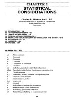
FIGURE 21.3 Some types
of
round-head
bolts,
(a)
Plain;
(b)
regular
square-neck;
(c)
short square-neck;
(d)
rib-neck;
(e)
fin-neck.
TABLE
21.11
Some
Basic
Dimensions
of
Round-Head
Bolts
(Inch
Series)
1
Nominal
Max.
head
Max.
head
Max.
square
size
diameter
A
height
H
width
W\
No. 10
0.469
0.114 0.199
i
0.594
0.145
0.260
k
0.719 0.176
0.324
J
0.844
0.2OS
0.3S8
A
0.969
0.239
0.452
i
1.094
0.270
0.515
i
1.344
0.344
0.642
i
1.594
0.406
0.768
I
1.844
0.469
0.895
1
2.094
0.531 1.022
fShort
square-neck
and
rib-neck
bolts
are
standardized only
to
j
in; fin-neck
bolts
are
standard only
to i in.
|Not
applicable
to
plain,
rib-neck,
or fin-neck
bolts.
TABLE
21.12
Some
Basic
Dimensions
of
Round-Head
Short
Square-Neck
Metric
Bolts
Nominal
Thread
Max.
head
Max.
head
Max.
square
size
pitch
diameter
A
height
H
width
W
M6 1
14.2
3.6
6.48
M8
1.25 18.0
4.8
8.58
MlO
1.5
22.3
5.8
10.58
M12
1.75 26.6
6.8
12.70
M14
2
30.5
7.9
14.70
M16
2
35.0
8.9
16.70
M20 2.5
43.0 10.9
20.84
21.3.3
Socket-Head
Cap
Screws
Figure
21.6«
illustrates
a
socket-head
cap
screw,
and
Fig.
21.6c
shows
a
flat
counter-
sunk-head
cap
screw.
Socket button-head
cap
screws resemble Fig.
21.Sa,
but
have
a
hex
or
spline driving socket instead
of the
slot. Head dimensions
for
these,
in
inch
and
metric sizes,
are
given
in
Tables 21.18
to
21.23 inclusive.
Thread-length formulas
are
L
r
=
2£>
+
0.50in
L
T
=
2D +
12
mm
(21.3)
Shorter
cap
screws
are
threaded
full
length.
Alloy-steel
cap
screws,
in
both inch
and
metric sizes, should contain
an
alloying
element, such
as
chromium, nickel, molybdenum,
or
vanadium,
in
such quantities
as
to
ensure that
a
hardness range
of 36 to 45
R
c
is
achieved.
TABLE
21.13
Basic Dimensions
of Hex Cap
Screws (Finished
Hex
Bolts)
and
Heavy
Hex
Screws
(Inch Series)
Fastener type
Heavy
hex
Fillet
radii Hex cap
screw screw
Nominal
I
I
I
size
Maximum
Minimum
WHWH
i
0.025 0.015
A
£
A
0.025 0.015
i H
\
0.025 0.015
&
iJ
1%
0.025 0.015
I
£
i
0.025 0.015
\
&
I
A
ft
0.045 0.020
ft
8
i
0.045 0.020
ti
S
IA
8
i
0.045 0.020
U
ti
U
U
i
0.065 0.040
1ft
S
lft
8
1
0.095 0.060
Ii
8
Ii
$
Ii
0.095 0.060
ltt
tt
lti
tt
Ii
0.095 0.060
Ii
S
2
S
Ii
0.095 0.060
2ft
%
2ft
%
Ii
0.095
0.060
21
IH
2j
ft
TABLE
21.14
Basic Dimensions
of
Metric
Hex
Screws
1
Type
of
screw
Nominal
Thread
CapJ
Formed}:
Heavy}:
Height Fillet
diameter pitch
W W
WH
radius§
M5
0.8 8 8
3.65
0.2
M6
1 10 10
4.15
0.3
M8
1.25
13 13
5.50
0.4
MlO
1.5 16 16
6.63
0.4
M12
1.75
18 18 21
7.76
0.6
M14
2 21 21 24
9.09
0.6
M16
2 24 24 27
10.32
0.6
M20
2.5 30 30 34
12.88
0.8
M24
3 36 36 41
15.44
0.8
M30
3.5 46 50
19.48
1.0
M36
4 55 60
23.38
1.0
fAll
dimensions
in
millimeters.
^Maximum.
§Minimum.
FIGURE 21.4 Standard
socket
shapes,
(a)
Forged
hex
socket;
(b)
forged
spline;
(c)
hex-socket
key.
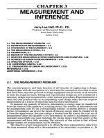
21.3.4
Shoulder
Screws
The
nominal size
D
s
shown
for the
shoulder screw
in
Fig.
21.6b
is
related
to the
max-
imum
and
minimum shoulder diameters
by the
relation
D
5
(max)
=
DS
-
0.002
£>
5
(min)
=
D
3
-
0.004
(21.4)
Sizes,
in the
inch series,
are
tabulated
in
Table 21.24.
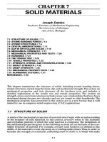
FIGURE
21.5
Hex-socket fasteners. From
left
to
right,
the
parts
are
identified
as
a
low
socket-head
cap
screw,
a
button-head socket
cap
screw,
a
socket shoulder
screw,
a
socket
set
screw,
a
socket-head
cap
screw,
a
socket
flat-head cap
screw,
a
hexagon key,
a
dowel
pin,
and a
socket pressure plug.
(Holo-Krome
Company.)
TABLE
21.15
Hex-Socket
Key
Sizes
(Inch Series)
fMaximum.
Nominal
width
W
0.028
0.035
0.050
Tk
£
A
A
J
&
£
A
£
i
*
J
4
i
ft
i
J
i
i
Short
arm B
Maximum
0.312
0.438
0.625
0.656
0.703
0.750
0.797
0.844
0.891
0.938
.031
.125
.219
.344
.469
.594
.719
.844
.969
2.219
2.469
2.719
Minimum
0.125
0.250
0.438
0.469
0.516
0.562
0.609
0.656
0.703
0.750
0.844
0.938
.031
.156
.281
.406
.531
.656
.781
2.031
2.281
2.531
Long
arm C
Shortsf
1.312
1.312
1.750
1.844
1.969
2.094
2.219
2.344
2.469
2.954
2.844
3.094
3.344
3.844
4.344
4.844
5.344
5.844
6.344
7.344
8.344
9.344
Longsf
2.688
2.766
2.938
3.094
3.281
3.469
3.656
3.844
4.031
4.219
4.594
4.969
5.344
6.094
6.844
7.594
8.344
9.094
9.844
11.344
12.844
14.344
TABLE
21.16
Spline-Socket
Key
Sizes (Inch Series)
Short
arm B
Long
arm C
Nominal
I
I
size
M
Maximum
Minimum
Shortsf
Longsf
0.033J
0.312 0.125 1.312
0.048
0.438
0.250 1.312
0.060
0.625 0.438 1.750
0.072 0.656 0.469 1.844
0.096 0.703 0.516 1.969
0.111
0.750 0.562 2.094
0.133 0.797 0.609 2.219 3.656
0.145 0.844 0.656 2.344 3.844
0.168 0.891 0.703 2.469 4.031
0.183 0.938 0.750 2.594 4.219
0.216
.031 0.844 2.844 4.594
0.251
.125 0.938 3.094 4.969
0.291
.219 1.031 3.344 5.344
0.372 .344 1.156 3.844 6.094
0.454 .469 1.281 4.344 6.844
0.595 .719 1.531 5.344 8.344
0.620 .844 1.656 5.844 9.094
0.698 .844 1.656 5.844
0.790 .969 1.781 6.344
fMaximum.
!This
size
has
only
four
splines.
TABLE
21.17
Basic
Maximum
Dimensions
of
Metric
Hex
Keys
f
Long
arm C
Nominal
Short
arm
I
size
W B
Shorts
Longs
0.7 5.5 34 62
0.9
9 34 62
1.3
13.5
44 84
1.5
14 45 90
2 16 50 100
2.5 18 56 112
3 20 63 126
4 25
70
142
5 28 80 160
6 32 90 180
8 36 100 200
10
40 112 224
12
45 125 250
14
56 140 280
17
63 160 320
19
70 180 360
22
80 200 400
24
90 224 448
27
100 250 500
fAll
dimensions
in
millimeters.
FIGURE 21.6 Socket
screws,
(a) Cap
screw;
(b)
shoulder screw;
(c) flat-head
screw.
The
maximum
and
minimum shoulder diameters
for
metric sizes
are
{
0.013
D
5
<10
0.016
10
<
DS
<
20
0.020
D
5
> 20
r
(
21
-
5
)
0.049
DS
<
10
Z>s(min)
=
D
5
-
-
0.059
10
<
D
5
<
20
^
0.072
D
5
> 20
TABLE
21.18
Basic Dimensions
of
Socket-Head
Cap
Screws (Inch Series)
Nominal Max. head Max. head
Hex
Spline Socket
size
D
diameter
A
height
H
size
W
size
M
depthf
T
0
0.096
0.060
0.050
0.060
0.025
1
0.1.18
0.073
h
0.072 0.031
2
0.140 0.086
£
0.096
0.038
3
0.161 0.099
&
0.096 0.044
4
0.183 0.112
A
0.111 0.051
5
0.205 0.125
i
0.111 0.057
6
0.226 0.138
&
0.133 0.064
8
0.270 0.164
&
0.168 0.077
10
0.312 0.190
£
0.183
0.090
i
0.375 0.250
li
0.216 0.120
&
0.469 0.312
i
0.291 0.151
J
0.562 0.375
&
0.372 0.182
A
0.656
0.438
I
0.454 0.213
i
0.750 0.500
i
0.454 0.245
I
0.938
0.625
i
0.595 0.307
3
1.125 0.750
I
0.620 0.370
I
1.312 0.875
i
0.698 0.432
1
1.500 1.000
I
0.790 0.495
U
1.688 1.125
I
0.557
U
1.875 1.250
i
0.620
IJ
2.062 1.365
1
0.682
Ii
2.250 1.500
1
0.745
fMinimum.
where
D
s
is, of
course,
in
millimeters.
See
Tables 21.24
and
21.25
for
basic dimensions
of
shoulder screws. These
are
made
of the
same material
and of the
same hardness
as
specified
for cap
screws.
21.3.5
Set
Screws
Socket
set
screws (Fig. 21.7)
are
available
in
both inch
and
metric sizes with either
hex
or
spline sockets
for the
inch series
and hex
sockets
for the
metric series.
The
cone point
in
Fig.
21.Ib
comes
in
seven
different
variations.
Square-head
set
screws (not shown) have
a
width across
flats
equal
to the
nomi-
nal
size
of the
screw.
The
head height
is
three-quarters
of the
nominal size. These
have
a
reduced-diameter neck
just
below
the
head.
21.3.6
Slotted-Head
Cap
Screws
The
three standard head styles
of the
inch-series
slotted-head
cap
screws
are
shown
in
Fig. 21.8,
and the
basic head dimensions
are
given
in
Table
21.26.
The
slot width
is
TABLE
21.19
Basic Dimensions
of
Socket-Head
Cap
Screws (Metric
Series)
1
Nominal
Max. head Max. head
Hex
Spline Socket
size
D
diameter
A
height
H
size
W
size
M
depthj
T
M1.6
3.00 1.60
1.5
1.829 0.80
M2
3.80 2.00
1.5
1.829 1.00
M2.5
4.50 2.50
2.0
2.438 1.25
M3
5.50 3.00
2.5
2.819 1.50
M4
7.00 4.00
3.0
3.378 2.00
M5
8.50 5.00
4.0
4.648 2.50
M6
10.00 6.00
5.0
5.486 3.00
M8
13.00 8.00
6.0
7.391 4.00
MlO
16.00 10.00
8.0
5.00
M12
18.00 12.00 10.0 6.00
M16
24.00 16.00 14.0 8.00
M20
30.00 20.00 17.0
10.00
M24
36.00 24.00 19.0
12.00
M30
45.00
30.00
22.0
15.00
M36
54.00
36.00
27.0
18.00
jAll
dimensions
in
millimeters.
^Minimum.
TABLE
21.20
Basic Dimensions
of
Socket Flat-Head
Cap
Screws
(Inch Series)
Nominal
Max. head Max. head
Hex
Spline Socket
size
D
diameter
A
height
H
size
W
size
A/
depthf
T
0
0.138 0.044 0.035 0.048 0.025
1
0.168 0.054
0.050
0.060
0.031
2
0.197
0.064
0.050
0.060
0.038
3
0.226 0.073
ft
0.072 0.044
4
0.255
0.083
ft
0.072 0.055
5
0.281
0.090
£
0.096 0.061
6
0.307
0.097
A
0.096 0.066
8
0.359 0.112
A
0.111 0.076
10
0.411
0.127
i
0.145 0.087
i
0.531 0.161
£
0.183 0.111
&
0.656 0.198
ft
0.216 0.135
I
0.781 0.234
A
0.251 0.159
ft
0.844 0.234
i
0.291 0.159
i
0.938 0.251
ft
0.372 0.172
i
1.188 0.324
3
0.454 0.220
J
1.438 0.396
i
0.454 0.220
i
1.688 0.468
ft
0.248
1
1.938 0.540
I
0.297
Ii
2.188 0.611
J
0.325
U
2.438 0.683
I
0.358
Ii
2.688 0.755
J
0.402
Ii
2.938 0.827
1
0.435
f
Minimum,
TABLE
21.21
Basic Dimensions
of
Socket Flat-Head
Cap
Screws (Metric
Series)
1
Nominal
Max. head Max. head
Hex
Socket
size
D
diameter
A
height
H
size
W
depthi
T
M3
6.72 1.85
2 18
M4
8.96 2.69
2.5 20
M5
11.20 3.18
3
'22
M6
13.44 3.58
4 24
M8
17.92 4.42
5 28
MlO
22.40 6.01
6 32
M12
26.88 6.85
8 36
M16
33.60 8.10
10 44
M20
40.32 8.70
12 52
M24
40.42 16.05
14 60
t
All
dimensions
in
millimeters.
^Minimum.
SOURCE:
Unbrako,
Division
of
SPS,
Jenkintown,
Pa.
19046
TABLE
21.22
Basic Dimensions
of
Socket Button-Head
Cap
Screws (Inch Series)
Nominal
Max. head Max. head
Hex
Spline Socket
size
D
diameter/*
height//
size
W
size
A/
depthf
T
0
0.114 0.032 0.035 0.048 0.020
1
0.139 0.039 0.050
0.060
0.028
2
0.164 0.046 0.050
0.060
0.028
3
0.188 0.052
*
0.072
0.035
4
0.213 0.059
*
0.072 0.035
5
0.238 0.066
A
0.096 0.044
6
0.262
0.073
A
0.096 0.044
8
0.312
0.087
£
0.111
0.052
10
0.361 0.101
4
0.145
0.070
i
0.437 0.132
A
0.183 0.087
&
0.547 0.166
A
0.216 0.105
J
0.656 0.199
A
0.251 0.122
i
0.875 0.265
&
0.372 0.175
i
1.000 0.331
i
0.454 0.210
!Minimum.
TABLE
21.23
Basic Dimensions
of
Socket Button-Head
Cap
Screws (Metric
Series^
Nominal
Max. head Max. head
Hex
Socket
size
D
diameter
A
height//
size
W
depth}:
T
M3
5.70 1.65
2
1.04
M4
7.60 2.20
2.5
1.30
M5
9.50 2.75
3
1.56
M6
10.50 3.30
4
2.08
M8
14.00 4.40
5
2.60
MlO
17.50 5.50
6
3.12
M12
21.00 6.60
8
4.16
M16
28.00 8.80
10
5.20
fAll
dimensions
in
millimeters.
{Minimum.
TABLE
21.24
Basic Dimensions
of
Socket Shoulder Screws (Inch
Series)
Shoulder Max. head Max. head
Hex
Socket Thread Thread
diameter
D
5
diameter
A
height
H
size
W
depthf
T
size
D
length
L
T
i
0.375
0.188
4
0.094
10
0.375
£
0.438
0.219
•&
0.117
I
0.438
j
0.562
0.250
A
0.141
£
0.500
i
0.750
0.312
i
0.188
i
0.625
I
0.875 0.375
&
0.234
i
0.750
3
1.000
0.500
i
0.281
I
0.875
1
1.312
0.625
i
0.375
3
1.000
H
1.750
0.750
i
0.469
i
1.125
Ii
2.125 1.000
i
0.656
Ii
1.500
Ii
2.375 1.125
1
0.750
U
1.750
2
2.750 1.250
U
0.937
Ii
2.000
fMinimum.
TABLE
21.25
Basic Dimensions
of
Socket-Head
Shoulder Screws
(Metric
Series)*
Shoulder Max. head Max. head
Hex
Socket Thread Thread
diameter
D
5
diameter
A
height
H
size
W
depth$
T
size
D
length
L
7
6.5
10.00 4.50
3 2.4 M5
9.75
8.0
13.00 5.50
4 3.3 M6
11.25
10.0
16.00 7.00
5 4.2 M8
13.25
13.0
18.00 9.00
6 4.9 MlO
16.40
16.0
24.00
11.00
8 6.6
M12
18.40
20.0
30.00
14.00
10 8.8 M16
22.40
25.0 36.00 16.00
12
10.0
M20
27.40
fAlI
dimensions
in
millimeters.
^Minimum.
f
0.16(XD
+
0.024
D
<
1
J=
\
(21.6)
[
0.160D
1
<
D
<
1/2
The
slot depth varies, depending
on the
head type
and the
nominal size.
Slotted-head
cap
screws
are
normally made
from
carbon steel conforming
to
ASTM A307 properties (see Table 21.7). However, they
can
also
be
obtained
in
grade
ASTM A449 material
and
properties.
21.3.7
Machine
Screws
We
can
keep track
of the
many types
of
machine screws
by
classifying
them
as
follows:
1.
Flat countersunk head
(80
degrees)
a.
Regular
or
undercut
b.
Slotted
or
cross-recessed
FIGURE 21.7
Socket
set
screws,
(a)
Flat
point;
(b) cup
point;
(c)
oval point;
(d)
cone
point;
(e)
half-dog
point.
2.
100-degree
flat
countersunk head
a.
Regular
or
close tolerance
b.
Slotted
or
cross-recessed
3.
Oval countersunk head
a.
Regular
or
undercut
b.
Slotted
or
cross-recessed
4.
Flat countersunk trim head
a.
Regular
or
short
b.
Cross-recessed
5.
Oval countersunk trim head
a.
Regular
or
short
b.
Cross-recessed
6.
Pan
head
a.
Slotted
or
cross-recessed
7.
Fillister head
a.
Slotted
and
cross-drilled
b.
Slotted
or
cross-recessed
8.
Truss head
a.
Slotted
or
cross-recessed
FIGURE
21.8
Slotted-head
cap
screws,
(a)
Round head;
(b)
flat
countersunk head;
(c)
fillister
head.
TABLE
21.26
Basic Head Dimensions
of
Slotted-Head
Cap
Screws (Inch Series)
Flat
headf
Round
headj
Fillister
headf
Nominal
I I
I
size
A H A H A H O
i
0.500 0.140 0.437 0.191 0.375 0.172 0.216
tfe
0.625 0.177 0.562 0.245 0.437 0.203 0.253
I
0.750 0.210 0.625 0.273 0.562 0.250 0.314
A
0.812 0.210
0.750
0.328 0.625 0.297 0.368
i
0.875 0.210 0.812 0.354 0.750 0.328 0.413
ft
1.000 0.244 0.937 0.409 0.812 0.375 0.467
J
1.125 0.281 1.000 0.437 0.875 0.422 0.521
3
1.375 0.352 1.250 0.546 1.000 0.500 0.612
J
1.625 0.423 1.125 0.594 0.720
1
1.875 0.494 1.312 0.656 0.803
U
2.062 0.529
U
2.312 0.600
Ii
2.562 0.665
Ii
2.812 0.742
fMaximum.
9.
Binding head
a.
Slotted
or
cross-recessed
10.
Hex
head
a.
Indented
b.
Slotted
c.
Indented
and
slotted
11. Hex
washer head
a.
Indented
b.
Indented
and
slotted
The
round-head
machine screw
is
obsolete.
Use the
pan-head screw, instead;
it
has
more driving power. Most
of the
head types outlined here
are
illustrated
in
Figs.
21.9
to
21.11,
some slotted
and
some with cross-recesses.
FIGURE
21.9
(a)
Slotted
flat
countersunk-head
machine
screw;
also
available
with
100-degree
head;
(b)
short
or
undercut
slotted
oval
countersunk-head
machine
screw.
Note
the
difference
between
the
body
of a
machine
screw
and
that
of a cap
screw.
Com-
pare
this
figure
with
Fig.
21.Sa.