Introduction to Modern Liquid Chromatography, Third Edition part 24 ppt
Bạn đang xem bản rút gọn của tài liệu. Xem và tải ngay bản đầy đủ của tài liệu tại đây (156.3 KB, 10 trang )
186 DETECTION
mass spectrometric (MS) detector is the most popular hyphenated HPLC detector in
use today (other hyphenated detectors are discussed in Section 4.15). MS detection
has become the standard detector system for bioanalytical methods—the analysis
of pharmaceutical compounds in biological systems (e.g., plasma or urine). MS
detectors are also widely used in the R&D setting to provide structural information or
confirmation of unknowns, although it does not have the mass-resolution capability
of traditional stand-alone mass spectrometers. MS detectors come in two popular
configurations. The single-stage detector, sometimes called an MSD (mass selective
detector), is used to measure a single ionic species for each analyte, often the
protonated molecular ion (M + H). (Within a given run, more than one analyte
ion can be monitored by switching back and forth between different m/z values or
scanning between ions.) Instruments using this type of detection are referred to as
LC-MS. A more complex detector design isolates the primary ionic species (parent
or precursor ion), fragments it into additional ions (daughter or product ions),
and monitors one or more of these product ions. This process, sometimes called
multiple reaction monitoring (MRM), gives added selectivity when the transition
from precursor to product ion is used as a ‘‘signature’’ of a specific analyte. Such
systems are referred to as LC-MS/MS. We will refer to LC-MS/MS when this specific
technique is used, and LC-MS for the single-stage methodology or when it is not
important whether the system is LC-MS or LC-MS/MS. A more detailed discussion
of MS detection as applied to gradient elution can be found in Section 8.1 of [13],
much of which is equally valid for isocratic separation. Additional information
about LC-MS and LC-MS/MS detection can be found in books dedicated to the
subject (e.g., [38–40]).
4.14.1 Interfaces
The development of the MS detector interface is perhaps the most important factor
in the successful application of mass spectrometry as an HPLC detection technique.
MS detectors manipulate and detect ions in the gaseous phase, so for the MS to
be useful as an HPLC detector, the mobile phase must be evaporated and sample
ions must be generated. This is the function of the MS detector interface. The
mobile phase is converted from liquid to gas phase, with an expansion in volume of
≈1000-fold; at the same time the pressure must be reduced from atmospheric
pressure (760 torr) to 10
−5
to 10
−6
torr within the 5 to 10 cm flow path of the
interface. Pressure is reduced by pumping most of the vaporized sample and mobile
phase to waste (no concentration takes place); only a tiny fraction of the sample is
drawn into the MS itself. The two most popular interfaces are electrospray ionization
(ESI) and atmospheric pressure chemical ionization (APCI).
4.14.1.1 Electrospray Interface (ESI)
The electrospray interface (Fig. 4.29) adds a charge to analytes in the mobile
phase by placing a potential (e.g., 3–5 kV) on the stainless-steel nebulizer spray-tip
(‘‘capillary’’ in Fig. 4.29). The mobile phase is sprayed into the heated interface,
where the solvent evaporates, leaving ions in the gaseous state. ESI is the most
commonly used interface for bioanalytical applications because it is a ‘‘softer’’
ionization technique and is less likely to cause undesirable analyte degradation.
4.14 MASS SPECTRAL DETECTORS (MS) 187
Figure 4.29 Schematic of the electrospray interface (ESI) for the LC-MS detector.
Figure 4.30 Schematic of the atmospheric pressure chemical ionization interface (APCI) for
the LC-MS detector.
4.14.1.2 Atmospheric-Pressure Chemical-Ionization Interface (APCI)
This interface (Fig. 4.30) vaporizes the mobile phase first, and then uses a corona
discharge to add a charge to the analyte in the gas phase. The APCI technique is
used for compounds that do not ionize well with ESI (often more stable, smaller
molecular-weight compounds and some nonpolar compounds), but under harsher
conditions, so it is more likely than ESI to cause sample degradation, especially
with heat-labile compounds. APCI has been shown to have fewer matrix-ionization
problems than ESI. APCI and ESI have different ionization mechanisms, so the
response and selectivity may vary significantly between the two interfaces. Either
188 DETECTION
interface can be operated in the positive- or negative-ion mode, resulting in the
generation of positively or negatively charged sample ions (most often achieved by
adding or removing a proton from the analyte molecule).
4.14.1.3 Other Interface Designs
Other interfaces are available for LC-MS besides ESI and APCI. For example, instead
of the corona discharge of the APCI, the atmospheric-pressure photoionization
interface (APPI) uses a UV lamp to generate photons, which in turn ionize the analyte.
At least one interface splits the column effluent to allow simultaneous generation of
ions using ESI and APCI, which can be useful for screening applications where the
sample ionization properties are not known.
4.14.1.4 Flow-Rate Considerations
To minimize the work required by the interface, a smaller column i.d. is selected
than is used for more traditional HPLC separations, so as to reduce the mobile-phase
flow rate. Although LC-MS interfaces can operate with a flow rate of 1 mL/min,
they are more reliable with lower flow rates. The use of 2.1-mm i.d. columns
allows the use of flow rates of 0.2 to 0.5 mL/min, with linear velocities (and
separation) comparable to flow rates used with conventional 4.6-mm i.d. columns
(1.0–2.5 mL/min). Short, 30- to 50-mm-long columns packed with 3- to 5-μm
particles provide fast separations of the usual (simple) mixtures encountered in
bioanalytical applications, namely an analyte, an internal standard, and one or two
metabolites. For more complex mixtures, longer column lengths (100–150 mm)
may be required, in order to obtain larger column plate numbers (with longer run
times). Capillary columns (e.g.,<1 mm) often are used with proteomics applications
and a ‘‘nanospray’’ interface designed for low- to submicroliter flow rates (Section
13.4.1.6).
4.14.2 Quadrupoles and Ion Traps
Two designs of mass filters are predominant for LC-MS (single-stage) applications:
quadrupoles and ion traps. Time-of-flight (TOF) designs (Section 4.14.3) also
are growing in popularity. Quadrupoles use a set of four rods and a carefully
controlled electric field to isolate selected ions from the sample. Ions of a selected
mass-to-charge ratio (m/z) are then passed to an electron multiplier for detection,
providing a selective response for the desired analyte. Ion traps use a ring electrode
in combination with end-cap electrodes to accomplish the same isolation of desired
ions, followed by detection. Both quadrupoles and ion traps can be set up to
change rapidly from monitoring one mass to another, and thus generate a spectrum
(scan) across a range of masses. An alternate mode of operation allows the detector
to ‘‘simultaneously’’ detect co-eluting compounds, such as an analyte and internal
standard, by switching back and forth between data collection channels for each mass
during the elution of the peaks. As discussed below, quadrupole MS detectors are
favored for quantitative analysis, whereas ion traps have advantages for qualitative
(structural) applications.
Single-stage MS detectors of the above-mentioned kind are used in less expen-
sive LC-MS units; however, additional structural discrimination is needed for more
4.14 MASS SPECTRAL DETECTORS (MS) 189
Figure 4.31 Triple quadrupole mass spectrometer. (a) Schematic; (b) MS/MS experiment for
A
+
>
A
+
b
precursor
>
product ion transition.
selective detection. The triple-quadrupole (Fig. 4.31a), or tandem, MS detector can
provide additional selectivity compared to that obtained with a single-quadrupole
unit. Sample ions generated in the interface (A
+
,B
+
,C
+
,D
+
in Fig 4.31b)enterthe
first quadrupole. The ions of a given m/z (A
+
) are isolated in the first quadrupole
and sent to a second quadrupole (collision cell), which is filled with an inert gas
(nitrogen or argon). The ions are fragmented (A
+
→A
+
a
,A
+
b
,A
+
c
) in the collision
cell and passed to a third quadrupole. The third quadrupole then isolates specific
ion fragments (e.g., A
+
b
) and passes them to the electron multiplier for measurement.
The transition from the initial ion (precursor or parent)tothefragmention(product
or daughter ion) provides a unique ‘‘signature’’ (A
+
>
A
+
b
in Fig. 4.31b)foran
analyte, and greatly increases the selectivity of the triple-quadrupole (MS/MS) over
the single-quadrupole detector. (Note that the conventional notation is ‘‘A
+
>
A
+
b
’’ to
represent the transition signature of the precursor A
+
to the product ion A
+
b
. We will
use this shorthand, while using ‘‘A
+
→A
+
a
,A
+
b
,A
+
c
’’ to represent the fragmentation
process itself.)
Ion traps accomplish multiple-stage fragmentation and the isolation of a
preferred product ion in the same physical space (vs. in different parts of the detector
as in the triple quadrupole of Fig. 4.31). First, ions are generated in the interface
and passed into the ion trap (ion accumulation, Fig. 4.32). Ions of a desired m/z are
held, while the remaining ions are sent to waste (ion isolation 1). The isolated ions
(A
+
in Fig. 4.32) are then fragmented (A
+
→A
+
a
,A
+
b
,A
+
c
) and the desired fragment
m/z is isolated (A
+
b
, ion isolation 2). The ions can then be sent to the electron
multiplier for detection or the process can be continued (further fragmentation
of A
+
b
, isolation, etc.). The ion trap is capable of performing this operation over
and over, isolating and breaking ion fragments into successively smaller fragments
(with a corresponding loss of sensitivity for each fragmentation step). This is useful
for structural identification, but historically the ion trap has not been as good for
quantitative work as the quadrupole because of space-charge effects (ion interactions
190 DETECTION
Figure 4.32 Ion-trap mass spectrometer. MS/MS experiment for A
+
>
A
+
b
precursor
>
prod-
uct ion transition. Note that the different boxes represent the same physical part of the system
at different times.
within the detector) and variability in the output signal intensity. Thus quadrupoles
(single and triple) tend to be more widely used for routine quantitative work,
whereas ion traps are preferred when structural identification is needed, such as in
metabolite isolation and identification.
4.14.3 Other MS Detectors
In addition to the quadrupole and ion trap, several other LC-MS detector configura-
tions are available. One of the most popular of these is the time-of-flight (TOF) MS
detector, as illustrated in Figure 4.33. In the TOF, ions are generated in the interface
and are accelerated with a specific energy and directed through a drift tube to the
detector. The velocity of an ion traveling through the drift tube will be related to
the amount of energy applied, so for the same applied energy, lower mass ions will
travel more quickly to the detector than will larger ions. The time taken to transit the
4.15 OTHER HYPHENATED DETECTORS 191
interface
drift tube
electron
multiplier
Figure 4.33 Linear time-of-flight (TOF) mass spectrometer.
drift tube is then correlated to the mass (m/z) of the ion. Mass resolution is related
to the length of the drift tube. Spatial limitations limit the length of the drift tube, so
one popular configuration uses an electrostatic mirror (‘‘reflectron’’) to increase the
effective length of the drift tube, and thus improve mass resolution. With sufficient
path length, the TOF can provide higher mass resolution than the quadrupole, so it
is useful for structural work. It should be noted, however, that none of the LC-MS
detectors have the mass-resolution capability of the more traditional, dedicated mass
spectrometers.
Many combinations of MS detector designs are available for MS-MS detection.
As mentioned above (Section 4.14.2), the triple quadrupole uses one quadrupole to
isolate the precursor ion, a second quadrupole as the collision cell for fragmentation,
and a third quadrupole for isolation of fragment ions. Two TOF sections can be
connected to a collision cell to provide similar function with a TOF-TOF. Mixing
the ion isolation sections is also possible. For example the Q-TOF uses a quadrupole
for the first stage, a collision cell, and then a TOF for the final stage. Each design
has certain advantages (and disadvantages)—and the instrument manufacturers are
glad to explain why their favorite configuration is better than all the others!
4.15 OTHER HYPHENATED DETECTORS
Hyphenated detectors, as defined in Section 4.2.2.4, refer to the combination of
an HPLC and another analytical instrument. It seems that nearly every stand-alone
analytical instrument has been connected to an HPLC system at some time or place,
so the number of possible combinations of hyphenated detectors is large. If each
detector provides quantitative and/or qualitative information about the sample, it
follows that multiple detectors attached to a single HPLC system could provide even
more information. In at least one case, four spectrometers were connected to a single
HPLC. This multiple hyphenation has been called ‘‘hypernation,’’ and is reviewed in
[41]. However, only LC-MS has reached the level of acceptance that it is used widely
and applied in nearly every application area of HPLC today. Two other hyphenated
detectors, infrared and nuclear magnetic resonance, also are commercially available
with HPLC interfaces. These detectors are used primarily as tools to aid structural
elucidation of unknowns in mixtures, rather than for routine quantitative analysis.
4.15.1 Infrared (FTIR)
Fourier transform infrared spectroscopy (FTIR) is a popular tool for providing
chemical structural information. When coupled to an HPLC system, IR data can
192 DETECTION
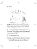
Figure 4.34 LC-FTIR response for E. coli extracts. (a) Composite chromatogram of largest IR
absorbance versus time; (b) individual FTIR spectrum for sample at 23 min (* in a). Adapted
from data of [41].
be obtained for separated components; that is, it makes possible IR analysis of a
mixture. The mobile-phase background spectrum can confuse interpretation of IR
spectra, so flow-through IR detectors are of limited use. An alternative is to use an
interface that evaporates the mobile phase and deposits the sample on a window
(e.g., ZnSe) that is transferred automatically into the IR instrument for analysis.
In this case, the detection is not continuous but rather in small, discrete samples.
(Sensitivity can be increased by increasing the time over which each IR reading takes
place, but this slows analysis time.) However, the data are sufficient for applications
such as that shown in Figure 4.34 for the LC-FTIR analysis of E. coli extracts
[42]. The sample was separated on a C18 column using a gradient of 0.1% formic
acid and acetonitrile. The composite chromatogram (Fig. 4.34a) was obtained by
plotting the largest IR absorbance value in every spectrum over time. The individual
spectrum at 23 minutes (*) is shown in Figure 4.34b. The spectrum is identified
as a protein by the various amide vibration bands at 1642, 1550, and 1268 cm
−1
(arrows) plus other spectral features. See [43] for a review of LC-FTIR.
4.15.2 Nuclear Magnetic Resonance (NMR)
Nuclear magnetic resonance (NMR) can be used as an HPLC detector in three
different operating modes [44]. In the simplest, the column effluent is directed
through the NMR flow cell and NMR data are gathered on-the-fly. Because of
time limitations, the sensitivity of this technique is low, but
1
HNMRhasproved
useful. Recent advances have enabled 2D NMR and
13
C NMR to be used in
flow-through mode for some applications. An alternate technique is stopped-flow
4.15 OTHER HYPHENATED DETECTORS 193
sampling, usually performed by trapping a segment of the chromatogram in a
loop and sending it to the NMR for stopped-flow analysis. Both flow-through and
stopped-flow LC-NMR must be used with proton-free mobile phases, so D
2
O often
is used instead of water (and deuterated ACN or CD
3
OD instead of MeOH), along
with narrow-bore columns to keep solvent consumption low. A third alternative is
LC-SPE-NMR, where a sample of column effluent is trapped on an SPE cartridge.
The cartridge can then be treated to remove any water, and the sample can be eluted
with a small volume of acetonitrile into the NMR cell for analysis. Both of the
latter techniques can be operated in short cycles (e.g., 20 sec) to minimize loss of
chromatographic resolution. See [45] for a review of LC-NMR.
Figure 4.35 shows an application of stopped-flow LC-NMR to the analysis
of organic matter in a water sample [46]. An gradient ion-pairing separation was
performed on a C
18
column using a mobile phase of 0.01M tetrabutylammonium
hydrogen sulfate in D
2
O (A-solvent) and acetonitrile (B-solvent), with 20-second
sampling into a holding loop across the regions of interest. NMR spectra were
obtained for selected regions of the UV chromatogram (Fig. 4.35a); the spectrum
of Figure 4.35b represents the aromatic region of the
1
H NMR spectrum for the
sample at 16 minutes (*) in Figure 4.35a.
Figure 4.35 Stopped-flow LC-NMR response for organic matter in water. (a) UV chro-
matogram for sample at 280 nm; (b)aromaticregionof
1
H NMR spectrum taken at (*).
Adapted from data of [46].
194 DETECTION
4.16 SAMPLE DERIVATIZATION AND REACTION DETECTORS
Despite the wide variety of HPLC detectors available today, some compounds cannot
be detected, or detection limits may not be sufficiently low for practical application.
One way around this problem is to derivatize the analyte to a new compound or
complex that will have sufficient response to conventional detectors (e.g., UV or
fluorescence). The derivatization reaction may be performed before the sample is
injected or after the analyte is eluted from the column. New derivatization reactions
are regularly reported in the literature, which should be consulted for detection
of specific compounds or compound types. Books of derivatization reactions are
available (e.g., [47]; also see references of Section 16.12), while a very practical
source for information is to consult the applications literature of the manufacturers
of reaction detectors (e.g., [48]).
Pre-column derivatization can be used to enhance detection limits, the chro-
matographic characteristics of the analyte (less often), or both. As a part of sample
pretreatment, pre-column derivitization may be done manually or in automated
fashion. Some autosamplers are designed to derivatize the sample just prior to
injection. Derivatization reactions can be instantaneous or slow, but if done in
batchwise fashion, even slow reactions may provide acceptable sample throughput.
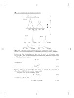
An example of pre-column derivatization to enhance the fluorometric detec-
tion of low-molecular-weight acids is shown in Figure 4.36 [49]. In this case,
9-chloromethylanthracene plus tetrabutylammonium bromide (a catalyst) is reacted
with the sample at 80
◦
C for 50 minutes as part of sample pretreatment. Fluores-
cence detection (excitation 256 nm, emission 412 nm) gave linear response of 1
to 250 ng/mL of monofluoroacetate in serum and a detection limit (S/N = 3) of
0.25-ng/mL serum.
Post-column derivatization (reaction detectors) involves reacting the sample
as it travels between the column outlet and the detector cell. This can be mediated
chemically, photochemically, or in combination. Table 4.9 summarizes some of
the desirable characteristics of a post-column reaction detector and the selected
chemistry. The detector design usually incorporates additional tubing between the
column and detector to provide reagent mixing and sufficient reaction time. However,
extra tubing will increase extra-column peak broadening, so the system must be
designed to balance reaction requirements with peak-broadening effects. One method
Time
(
min
)
1
2
3
4
5
0246810
Figure 4.36 Pre-column derivatization of organic acids to provide fluorescence response
(excitation at 256 nm, emission at 412 nm). 1, 9-Chloromethylanthracene derivatization
reagent. Derivatives of 2, monofluoroacetate; 3, formic acid; 4, acetic acid; 5, propionic acid.
Adapted from data of [48].
4.16 SAMPLE DERIVATIZATION AND REACTION DETECTORS 195
Table
4.9
Requirements of Post-column Reaction Detection
Minimum dispersion
Completeness of reaction in a short time
Reproducibility
Stability of reagents
Solubility of reagents and products
Minimum detector response to reagents
to reduce extra-column peak broadening during reaction is to use a knitted reactor,
where narrow-bore flexible tubing is knitted into a series of tight radius bends to
create turbulent flow and reduce dispersion. Generally, a fast reaction is desired to
minimize the reactor volume requirements. Also reactions that go to completion tend
to be more reproducible than those that only go partially to completion. The reaction
chemistry must be chosen so that the reagents are sufficiently stable to use over the
course of a batch of samples, and both the reagents and the reaction products must
be soluble in the mobile phase. Of course, the reagents should not interfere with
detection of the product, so detector response to the reagents should be minimal.
Reagent kits for popular post-column reactions (e.g., orthophthaldehyde, OPA, and
ninhydrin for amino acid analysis) are commercially available. The purchase of such
kits is convenient and provides standardized concentrations and quality control of
reagents that may not be available when performing in-lab formulation of reagents.
1200 20406080100
Time
(
min
)
1
2
3
5
7
8
10
9
12
13
15
16
19
17
18
20
22
21
23
24
25
26
27
28
29
30
31
32
33
34
35
37
38
39
40
44
42
41
43
45
36
14
11
4
6
Figure 4.37 UV response at 405 nm after post-column derivatization with ninhydrin of 45
amino acids and related compounds. Courtesy of Pickering Laboratories, Inc.