An Encyclopedia of the History of Technology part 64 pdf
Bạn đang xem bản rút gọn của tài liệu. Xem và tải ngay bản đầy đủ của tài liệu tại đây (205.95 KB, 10 trang )
PART THREE: TRANSPORT
612
Throughout the nineteenth century, ballooning was largely an activity for
showmen, with a limited number of ascents for scientific (mainly
meteorological) purposes. Most of these flights were made using coal-gas,
which was conveniently available in most towns from about 1820. Charles
Green was the first to use coal-gas in London in 1821; although the Academy
of Lyons had suggested it in 1784. Coal gas is heaver than hydrogen, so a
somewhat larger balloon was needed, but the lower cost and the convenience
of inflating from a permanent supply were great advantages.
Hot-air balloons were used occasionally during the nineteenth and early
twentieth centuries, but their very large size compared to gas balloons made
them difficult to handle, and it was only when sheer size was a desirable
feature required by an entrepreneur that they were noticed. However, it was
often realized that if a continuous supply of heat could be contrived, hot-air
balloons could be useful in remote places where coal gas or hydrogen was not
conveniently available. Experiments on these lines were regularly made, using
alcohol or petroleum fuels, from the latter part of the nineteenth century
onwards.
Another interesting but abortive proposal was to combine the constant lift
of a hydrogen balloon with the variable lift of a hot-air balloon carrying a
fuel supply. This concept was first tried by Pilâtre de Rozier, the pilot of the
first Montgolfier balloon, in 1785. He made a combination balloon which
had a conventional hydrogen balloon on top of a cylindrical bag heated by a
brazier, fuelled with straw blocks. Its only flight, on 15 June 1785, was an
attempt to cross the English Channel from Boulogne; this ended in disaster
when the balloon caught fire after a few minutes’ flight. Subsequent attempts
to produce combination balloons were equally unsuccessful, though not so
spectacularly fatal.
Although the use of balloons for military observation purposes was
pioneered by the French in 1794, it was neglected thereafter. During the
Franco-Prussian War of 1870 attention was focused on the successful use of
free balloons to allow individuals and dispatches to leave Paris during the
seige; tethered observation balloons were employed on both sides but were not
significantly useful. However, in the aftermath of the war, experiments were
resumed in Britain, France, Germany and elsewhere into the use of captive
balloons for observation work. The major technical advances arising from this
work were the development by the British army of steel cylinders to hold
compressed gas and special wagons to carry them; and portable winches to
raise and lower the balloon quickly. Electrolysis of water was also introduced
as an alternative method of generating acid-free hydrogen on a large scale.
It was soon realized that in strong winds, a spherical balloon was very
unstable when tethered, especially near the ground. Two German officers,
Major von Parseval and Captain von Sigsfeld, developed (about 1896) an
elongated balloon with large inflated tail-fins which flew at an angle to the
AERONAUTICS
613
wind, like a kite, and was much more stable. Such kite-balloons were then
taken up by most other countries; a version invented in 1916 by the
Frenchman Albert Caquot supplanted the Parseval design during the First
World War. Apart from their use at the front for observing the results of
artillery bombardment, Caquot balloons were used also as an anti-aircraft
screen around London—the so-called ‘balloon barrage’—and this use was
repeated on a large scale in the Second World War.
After a number of high-altitude balloon flights in which the pilots were
killed, a sealed pressurized cabin was first used by the Swiss scientist Auguste
Piccard in 1931 for a flight to 15,780m (51,775ft) to investigate cosmic
radiation. The spherical aluminium cabin or gondola was designed and made
in Belgium, but closely resembled a published design of 1906 by Horace Short
which was never built. Piccard’s balloon was made of rubberized cotton, and
dispensed with the conventional net—the gondola was supported from a band
sewn into the envelope.
A number of similar flights were made in the 1930s in several countries.
The last pre-war flight, by the Americans Stevens and Anderson, used helium
as the lifting gas, and reached 22,066m (72,395ft).
Helium was identified as a minor constituent of natural gas in some
American oilfields in 1907, and its potentialities for inflating balloons and
airships were realized on the outbreak of the First World War. Although
heavier than hydrogen, it is completely non-flammable. Several plants were
installed to separate helium from natural gas in the United States in 1917–18;
the American military services prohibited its export and from 1923 it replaced
hydrogen entirely in US military airships, but was rarely used in balloons
because of the cost.
The resumption of high-altitude balloon flights for cosmic ray research after
the Second World War utilized the recently developed lightweight polythene
films for the envelope. Initially these were not thought safe enough for manned
flight, so from 1947 a series of unmanned flights was made using helium-filled
balloons developed by the American Otto Winzen and funded by the US navy
and air force. Eventually a number of manned flights were made in the USA
with polythene balloons between 1956 and 1961.
A by-product of these high-altitude flights was the revival of hot-air
ballooning. In 1960, the American Paul E. Yost introduced the ‘Vulcoon’, with
an envelope made of nylon fabric laminated with an internal mylar plastic film.
Commercially available propane gas cylinders (normally used for fuelling
portable cooking stoves) fed a burner system which heated the air in the
balloon. The single pilot sat on a sling, although small wicker or aluminium
baskets were soon introduced. Although nominally developed as a military
project by Yost’s company Raven Industries, these new hot-air balloons were
primarily produced for sport-flying. After a somewhat hesitant start, the revival
of hot-air ballooning spread world-wide during the 1970s, and improved
PART THREE: TRANSPORT
614
designs of envelopes and burners made it possible to build a large variety of
sizes and shapes, including many novelties to advertise commercial products.
The new fabric technology was also applied to gas balloons, and long-
distance flights lasting several days became possible. The first successful
balloon flight across the Atlantic was made by the Americans Ben L.Abruzzo,
Max L. Anderson and Larry Newman in August 1978 in a helium-filled
balloon.
AIRSHIPS
Almost as soon as the free balloon had been invented, attempts were made to
control its direction of flight, by using hand-operated paddles (tried by Lunardi in
1784), airscrews (Blanchard, 1784) or even by letting out a jet of hot air from the
side of the envelope (Joseph Montgolfier, 1784). It was soon realized that it would
be an advantage to reduce the cross-section area of the balloon, so elongated and
pointed shapes were proposed. The French General J.B.M.Meusnier produced a
detailed design for such a dirigible balloon or airship in 1785; it had the form of an
ellipsoid, 79m (260ft) long with a capacity of 60,000ft
3
(1700m
3
), and was intended
to be driven by manually-powered airscrews.
Meusnier’s most significant invention in this design was the ballonet—an
air-bag inside the envelope, into which air was pushed by a bellows to
maintain internal pressure inside the airship. Varying the amount of air in the
ballonet compensated for changes in the volume of hydrogen as the altitude
of the ship changed, while maintaining the external shape of the envelope.
Although Meusnier’s airship was never built, it embodied many of the
features of later designs.
As long as manual effort was the only available power source to propel an
airship, little progress was possible. The idea of using a pair of horses
working a treadmill was proposed in a design by Dr E.C.Génet in 1825, but
the first satisfactory power source was a 2.25kW (3hp) steam engine
employed by the French engineer Henri Giffard in 1852. This unit, with its
coke-fired boiler, was slung some 12m (40ft) below the cigar-shaped
envelope, which was 44m (144ft) long and contained 2500m
3
(88,000ft
3
) of
hydrogen. Giffard’s airship was calculated to have a maximum speed of
10kph (6mph) in still air, so in practice it was impossible to fly to a pre-
determined destination except down-wind.
An Austrian engineer, Paul Haenlein, was the first to build an airship with
an internal combustion engine; in 1872 he constructed a four-cylinder gas
engine of Lenoir pattern, but it was too heavy for his balloon which was never
flown. He was followed by two French army engineers, Charles Renard and
Arthur Krebs, who in 1884 flew their airship La France powered by an electric
motor of 6.5kW (8.5hp) supplied with current from batteries. This is usually
AERONAUTICS
615
regarded as the world’s first successful airship, since it was able to return to its
starting point on five of its seven flights; however, it was capable of no more
than 24kph (15mph) in still air so was only able to fly in the lightest breezes.
With the development of petrol-engined road vehicles in 1886 (see Chapter
8), it seemed that a suitable power unit for airships had appeared. The German
engineer Karl Woelfert, in conjunction with Gottlieb Daimler, produced an
airship with a 1.5kW (2hp) single-cylinder Daimler engine which was test-
flown in 1888. This was too small to be practicable; Woelfert’s next airship
with a 4.5kW (6hp) Daimler engine probably never flew because it lacked
sufficient lift; and a larger airship built for trials by the Prussian army in 1897
caught fire and killed the inventor on its only flight in Berlin. In the same year,
at the same place, a unique all-metal airship designed by the Austrian David
Schwarz and fitted with a Daimler engine was wrecked on its first trial flight.
In France, the Brazilian amateur enthusiast Alberto Santos-Dumont fitted a
1.5kW (2hp) De Dion-Bouton engine in the first of a series of small airships
which he flew fairly successfully. In 1901, in his No. 6 airship, he just
succeeded in flying from St Cloud to the Eiffel Tower and back inside the time
limit of 30 minutes and thus won a prize of 100,000 francs offered by Henri
Deutsch de la Mearthe. The enormous publicity surrounding this flight gave
Santos-Dumont’s airships a rather unwarranted reputation, for in truth they
were hardly capable of outflying Renard and Krebs’ La France of 1884.
Inspired by Santos-Dumont’s activities, the French Lebaudy brothers, owners
of a large sugar refinery, commissioned their chief engineer Henri Julliot to build
a much larger airship. This machine Lebaudy I was 57m (187ft) long with a
capacity of 2250m
3
(80,000ft
3
); a 30kW (40hp) Daimler engine driving two 3m
(9ft) diameter airscrews gave it a speed of about 40kph (25mph) and it was the
first really practical airship when it flew in November 1902.
During the next ten years a considerable number of essentially similar airships
were made in several European countries, and these were further developed
during the First World War. Most were non-rigid airships, colloquially known as
Blimps, which had envelopes made of rubberized cotton or linen fabric, whose
shape was maintained by having the gas at slightly greater than atmospheric
pressure: this pressure was generated by forcing air into internal ballonets by
scoops behind the propellers. The car (often called a gondola) containing crew and
engines was slung beneath the envelope, usually hanging from support patches
sewn into the fabric (see Figure 12.1). The so-called semi-rigid airships (which
included the Lebaudy types) had a rigid keel of wood or a metal framework,
attached directly to the bottom of the envelope; the car was slung from this.
Probably the largest of the non-rigid airships built during this period were
the British North Sea class of 1917, with two 250hp (166kW) engines and a
crew of ten; these were 80m (262ft) long with a capacity of 10,000m
3
(360,000ft
3
). During and after the Second World War much larger airships of
this general type, filled with helium, were developed by the US navy,
PART THREE: TRANSPORT
616
eventually culminating in the Goodyear ZPG-3W of 1958 with a capacity of
42,500m
3
(1.5 million ft
3
), powered by two 1120kW (1500hp) engines. These
carried early-warning radar systems for fleet protection, with large aerials
inside the envelope.
Small non-rigid airships continue to be built in the 1980s, using modern
synthetic materials for the gas-bag and cabins; the basic configuration,
however, remains essentially similar to the successful Blimps of the First
World War.
The ‘semi-rigid’ design was particularly developed in Italy, the largest being
the Roma of 34,000m
3
(1.2 million ft
3
), launched in 1919. Its six 500hp engines
gave a maximum speed of almost 70mph. This was sold to the United States
and its destruction by fire in 1922 caused the US military authorities to use
only helium for inflating their airships thereafter.
The largest and most spectacular airships were the ‘rigids’, which had a
wooden or metal framework structure, covered externally with a fabric skin,
and containing a number of internal gas bags to provide lift. Accommodation
for the crew and passengers was either in a cabin attached directly to the main
hull, or in a separate gondola slung below it. Engines were slung from the hull,
usually in discrete pods distributed along the length of the ship.
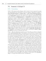
Figure 12.1: A ‘Coastal’ class airship of the Royal Naval Air Setting setting off for
an anti-submarine patrol during the First World War, 1914–18. This is a typical
non-rigid airship, inflated by hydrogen, and powered by two 112kW (150hp)
Sunbeam engines.
AERONAUTICS
617
The ill-fated Schwarz metal airship was technically a rigid airship, for it had
an internal structure of metal tubes supporting the external skin, but the
accepted originator of the classical rigid airship was Count Ferdinand von
Zeppelin. His first design, LZ.1, was developed with the assistance of Professor
Müller-Breslau, a structural engineer. A framework of internally-based ring
girders joined by longitudinal members was made in aluminium—the whole
structure being a 128m (420ft) long cylinder of 11.75m (38.5ft) diameter with
tapered ends. Two gondolas were slung beneath the hull, each containing a
10.5kW (14hp) Daimler engine. Seventeen individual gas bags made of cotton
with a rubber lining were installed between the frames, and the outside of the
hull was covered in a varnished cotton fabric. LZ.1 was launched in 1900, and
flew only three times because it had inadequate controls. A second ship, LZ.2,
built in 1905, introduced triangular section girders made of the new high-
strength duraluminium alloys. This had two 63kW (85hp) motors and a more
satisfactory control system, but crashed on its second flight. However, LZ.3 of
1906 proved sufficiently successful to spawn a long line of airships, and
successful passenger-carrying services were operated from 1911 with LZ.10
and three other ships. The main uses of Zeppelins were to be for military
purposes, and notably for the inauguration of night-bombing attacks on French
and British targets, in which they were able to avoid the opposition of guns
and aeroplanes by flying at altitudes above 6000m (20,000ft).
There were other rigid airships, notably the wooden-framed German
Schutte-Lanz designs of 1911–18. The British government sponsored a series
of designs culminating in the passenger ships R100 and R101 (Figure 12.2) of
1929, and the US Navy purchased the Akron and Macon built by Goodyear
(with considerable Zeppelin input) in 1931–3; but the Zeppelin company
continued to dominate the field. Their LZ.127 Graf Zeppelin, built 1928, was
236m (775ft) long with a volume of 106,000m
3
(3.7 million ft
3
), and operated
passenger services on a regular schedule across the South Atlantic for several
years. However, the spectacular losses of the British R.101 in 1931 and the
LZ.129 Hindenburg in 1937, following a series of earlier accidents, brought
about a cessation of work on rigid airships. Although new designs were
proposed in the 1970s using modern materials and various novel design
principles, it seems unlikely that the rigid airship will reappear.
HEAVIER-THAN-AIR FLYING MACHINES: THE
PIONEERS
An entirely new approach to achieving dynamic flight with heavier-than-air
apparatus was initiated by Sir George Cayley, a scholarly Yorkshire landowner
with wide practical interests who remained fascinated by flying throughout his
life. Although at various times he worked on model helicopters and clockwork
PART THREE: TRANSPORT
618
Figure 12.3: Sir George Cayley scratched this sketch (a) on a small silver disc in
1799 to illustrate his concept that the aerodynamic force on a wing could be
resolved into lift and drag. On the other side (b) he shows an aircraft with the
wing, a boat-shaped nacelle for the pilot, a controlling tail unit and a pair of
propulsive flappers.
Figure 12.2: The British airship R101 leaving the passenger access tower at
Cardington during test flying, October 1929. Water-ballast is being discharged
near the nose, and the four ‘forward’ engines are stationary while the ship is
maneuvered by the ‘reverse’ engine.
AERONAUTICS
619
powered airships, his main contribution was to formulate clearly the basic
principle of dynamic flight using a rigid wing surface to provide lift and a
separate propulsion unit to provide forward motion (see Figure 12.3). In a
classic paper published in three numbers of Nicholson’s Journal of Natural
Philosophy (November 1809–March 1810), he summarized the basic principle in
the words:
The whole problem is confined within these limits, viz. To make a surface
support a given weight by the application of power to the resistance of air.
In 1804 he had measured the lift produced by a flat plate moving through
the air at a small angle of incidence, using a whirling arm driven by a falling
weight, similar to that used by John Smeaton in 1752 for comparing various
designs of windmill (see Chapter 4). With the data thus obtained he was able
to design and make model gliders incorporating a kite-like wing and a
stabilizing tail unit. He also found that the stability of his gliders in the lateral
plane was improved by bending the wing to incorporate a dihedral angle.
There is some evidence that he built what would now be called a hang-glider
in about 1810—a full-size winged machine supporting a man who launched it
by running forward (probably downhill) and controlled its flight by moving his
body. Towards the end of his life he made two gliders which certainly carried a
live load—a ‘boy-carrier’ in 1849 and a ‘man-carrier’ in 1853. Unfortunately
the evidence for their construction and operation is little better than anecdotal
and although it is clear that a controlling tail unit was fitted at least to the later
machine, it is not clear whether the occupant could really control the flight
path to any significant extent.
Although Cayley experimented with hot-air engines, clockwork springs and
even a gunpowder motor as potential power units, he never solved the problem
of propelling his aircraft and was consequently unable to exploit his vision that
an uninterrupted navigable ocean, that comes to the threshold of every man’s
door, ought not to be neglected as a source of human gratification and advantage
(1816).
STEAM POWER
Most of Cayley’s work was never published, and although the significance of
his paper of 1809–10 was later well recognized, it had less influence on his
contemporaries than he had hoped. However, he did directly inspire William
Samuel Henson, whose widely publicized patent of 1843 for an Aeriel Steam
Carriage fixed the idea of Cayley’s classical aeroplane shape in the minds of
later workers. Henson postulated a high-wing monoplane with cambered wing
PART THREE: TRANSPORT
620
section, externally braced with streamline wires to reduce drag, with a separate
fuselage containing accommodation for passengers and crew, and housing a
steam engine which drove two airscrews behind the wing. A large tail unit
comprising horizontal and vertical rudders was intended to steer the machine.
The most impractical feature of Henson’s machine was the intention to
launch it down an inclined rail. The idea was to use the force of gravity to
accelerate the aircraft, so the steam engine needed only to be sufficiently
powerful to overcome drag in forward flight. Clearly Henson recognized that
the weight of the power plant—including boilers, fuel and water—would be
critical, and must be kept as small as possible.
Henson’s project was never built, though there is evidence that contracts
were placed for construction of the airframe and engine. The company formed
to exploit it suffered much ridicule as a result of its excessively optimistic
publicity for passenger-carrying services to India and China, and the scheme
foundered.
Henson then combined with John Stringfellow to test a large model of
about 6.6m (20ft) wingspan—something that might prudently have been done
earlier. However, no real success was obtained, partly because the trials (on a
hillside near Chard in Somerset) were conducted at night to maintain secrecy
and avoid ridicule. These tests were made in 1847; in the next four years or so
Stringfellow continued the work alone, building a number of models and light
steam engines. Limited success was obtained, but any real demonstration of
free flight was prevented by Stringfellow’s lack of a suitably large building in
which to fly his models. In 1851, frustrated by lack of funds to procure such a
building, he postulated ‘an Aerial tent of canvass or calico rendered impervious
to air and to be filled and kept up by a blowing machine so that no timber
would be required to support it’. This imaginative prevision of the inflated
structures of the late twentieth century remained as no more than an idea.
Stringfellow briefly resumed his aeronautical work around 1866, stimulated
by the formation of the Aeronautical Society of Great Britain under the
presidency of the Duke of Argyll; at the Society’s Exhibition at the Crystal
Palace in 1868, he exhibited a steam powered triplane which seems to have
been rather less successful than his model of 1848. He also exhibited one of his
earlier small steam engines, and received a prize for it as the lightest practical
power unit entered.
Steam power being virtually all that was available in the nineteenth century,
it is not surprising that it was employed by later inventors, who made little
further progress towards successful mechanical flight. Clément Ader, a famous
French electrical engineer, built his Eole between 1882 and 1890, with a 15m
(49ft) wingspan patterned on the model of a bat. Driven by a steam engine of
about 13.5kW (18hp) and piloted by Ader himself, it made a single straight-
line ‘flight’ of about 50m (160ft) just clear of the ground on 9 October 1890.
Inspired by this, Ader was funded by the French government in 1892 to make
AERONAUTICS
621
a new machine which appeared in 1897. This Avion III (No. 2 having been
abandoned before completion) had two steam engines driving curious
feathered propellers, and huge bat-like wings of complex construction. It was
twice tested in October 1897, but failed totally to fly and was blown off its
track and damaged on the second attempt, after which the War Ministry
refused further support. The machine still exists in a French museum and is
the oldest full-size ‘aircraft’ to survive.
Equally abortive was the enormous steam-powered test-rig built by Sir
Hiram Maxim in Kent in 1893–4. After extensive tests of aerofoils and other
components on a whirling arm and in a wind tunnel, Maxim built a carriage
propelled by two very lightweight steam engines of 135kW (180hp) each,
running on a level railway track some 550m (1800ft) long. On this carriage
were mounted wing surfaces extending to some 400m
2
(4000ft
2
), which were
assembled in various configurations. The lift and drag developed were
measured, and the carriage was restrained from rising more than a few
centimetres by outrigged wheels running beneath a set of guard rails alongside
the main track. Although testing continued for a couple of years, nothing came
of it. Maxim did not attempt to build a real flying machine until 1910, and that
was totally unsuccessful. He ascribed his failure variously to lack of money,
inability to find a sufficiently large open space to continue trials, and to the
need to develop a better power-plant. The last reason is certainly valid, but the
real reason for his procrastination seems to have been a fear that he might be
subject to ridicule if he failed.
GLIDERS
The first man to make repeated flights with a heavier-than-air machine was
the German Otto Lilienthal. His original intention was to develop an
ornithopter, but lacking a suitable power source he developed a series of
fixed-wing gliders between 1891 and 1896. These machines were launched
from a variety of eminences, including a special constructed earth mound
some 15m (50ft) high. He supported himself from his forearms, placed
through sleeves under the wing roots, with his lower body hanging below the
wing, launched himself by running downhill into the wind, and controlled
the flight by swinging his body to manipulate the centre of gravity. His
gliders were fairly crudely made, with a single-surface fabric wing supported
by wooden spars which could be folded up for easier portability. The
machines themselves were not technically significant, but the publicity given
to his numerous flights was a spur to other workers, particularly as for the
first time photographic illustrations of a man flying successfully were given
wide circulation. The publicity given to Lilienthal’s flying was enhanced
when he was killed by a crash in August 1896.