An Encyclopedia of the History of Technology part 33 doc
Bạn đang xem bản rút gọn của tài liệu. Xem và tải ngay bản đầy đủ của tài liệu tại đây (155.26 KB, 10 trang )
PART TWO: POWER AND ENGINEERING
302
Figure 5.9
STEAM AND INTERNAL COMBUSTION ENGINES
303
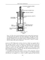
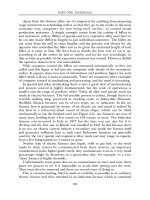
Figure 5.9: Vertical section of the 1300MW, 3600rpm cross-compound turbine
built by Brown, Boveri & Co. and installed at the Gavin station of the American
Electric Power Co. in 1974. Steam inlet conditions: 241bar (3500psig), 538°C
(1000°F) with single reheat to 538°C (1000°F). This is the largest steam turbine
in the world supplied by a fossil-fuel fired steam generator.
Although this turbine is described as a cross-compound (introduced c.1914)
because sections of the machine are divided to drive two separate loads, it also
incorporates tandem compound features (introduced c.1913) because the high
pressure (upper left) and intermediate pressure (lower left) sections are coupled
to the low pressure sections (on the right). All sections are double flow
(introduced c.1906) with steam supply at the centre point of the section. The
steam flows in opposite axial directions balancing any thrust on the rotors from
the stage pressure drops. The high pressure section is supplied with steam from
the steam generator. This section then exhausts, through the reheater, to the
intermediate pressure section, which in turn exhausts to the four low pressure
sections. Double shell construction (introduced 1937) is used in all sections.
The increasing inlet temperatures and pressure shown in Figure 5.10 are a
consequence of the desire to increase the efficiency of the thermodynamic cycle
of which the steam turbine is a part. The result has been a considerable
improvement in cycle efficiency over the years as indicated by the decreasing
plant heat rate. Reliability is as important as efficiency, and the continual
advances in steam conditions and power output have required a corresponding
effort in metallurgy, material behaviour and inspection, blade and disc
vibration, and fluid mechanics. The fact that reliability has been maintained
with the continuing need to increase the turbine operating parameters is a
monument to the engineers who have made it possible.
INTERNAL COMBUSTION ENGINES
The reciprocating internal combustion engine was the second type of thermal prime
mover, after the reciprocating steam engine, to be developed, with the first practical
example, the Lenoir engine, being built in 1860. There were three incentives to
replacing the steam engine: (a) elimination of the boiler and condenser, and the
need for good water; (b) the increasing availability of suitable fuels: coal-gas and
petroleum derivatives; (c) the potentially higher thermal efficiency of the internal
combustion engine, as indicated by thermodynamics, resulting from the higher
allowable maximum temperatures compared to other prime movers.
Three fuels, gas, petrol (gasoline) and oil are in normal use in the internal
combustion engine. In addition, there have been, and there are, efforts to use
coal as a fuel (although contrary to myth, Rudolf Diesel did not originally intend
this for his engine). Engines can, therefore, be classified by the fuel they employ.
Alternatively, engines may be categorized by the method used to ignite the fuel;
PART TWO: POWER AND ENGINEERING
304
a hot surface, a spark or compression of the working substance. The modern
tendency appears to favour the last method. Accordingly, the following
nomenclature has been adopted here: the spark ignition engine describes
essentially the modern petrol engine and its forebears; the compression ignition
engine refers to what is now commonly known as the Diesel engine (which is
not the machine originally invented by Diesel). Two additional classes,
described further below, are the gas engine and the ‘hot bulb’ engine.
Proposals and developments before 1860
The development of the internal combustion engine began in the seventeenth
century with attempts by Christian Huygens to harness the energy released in
Figure 5.10: Historical trend of the performance parameters of steam turbines in
electric power generation service 1890–1985.
The plotted curves represent the ‘average’ or ‘typical’ machine. The progressive
increase in inlet steam temperature is particularly dependent on the materials
used in the rotors and casings. Periods of application of different materials are
roughly as follows: cast iron: 1883–1913; cast steel (ferritic): 1913–37; alloy steel
(chrome ferritic): 1930 to date; alloy steel (austenetic): 1947–76. To convert the
heat rate values to efficiency multiply by 2.93×10
-4
and invert. The curves are
based on data in K.Baumann, Journal of the Institution of Electrical Engineers, vol. 48
(1912), pp. 768–877; vol. 59 (1921) pp. 565–663, and The Metropolitan-Vickers
Gazette, vol. 12 (1930), pp. 212–20, and the annual power plant surveys
appearing under various titles in Power between 1931 and 1985.
STEAM AND INTERNAL COMBUSTION ENGINES
305
a cannon on firing. This was done by exploding a charge of gunpowder at the
base of a vertical cylinder, closed at its lower end; the expanding products of
combustion raised a free-piston fitted in the cylinder. If some of the products of
combustion were released when the piston reached its point of maximum
travel, then the residual gases would, on cooling and contracting, produce a
pressure less than atmospheric (a vacuum) in the cylinder below the piston.
The application of this vacuum to power production was the same as that in
the steam engine (see p. 273).
The free-piston engine is not convenient for producing mechanical power
because on the upward (expansion) stroke the piston has to be disconnected
from the output shaft. An atmospheric engine with a conventional permanent
connection to its load was first demonstrated by William Cecil in 1820. This
was a hydrogen fuelled, single acting, atmospheric engine that drove its load
through a rocking beam (like Newcomen’s steam engine: see p. 275) and
crank. It was spark ignited, and Cecil designed an automatic device for
metering and mixing the air-fuel mixture.
Samuel Brown, a Londoner, constructed between 1823 and 1833 the
first commercially successful internal combustion engine. A vacuum was
produced in a constant volume container by burning coal-gas and cooling
the products of combustion with a water spray (as in Watt’s steam engine:
see p. 275). The vacuum was then used in a separate power cylinder, fitted
with a piston.
A free-piston engine was designed and built, between 1854 and 1864, by
the Italians Eugenio Barsanti and Felice Mattucci. This was a return to the
original concept of Huygens, but the fuel was now coal-gas with spark ignition.
For various reasons it was not a commercial success.
1860–1880: the early gas engine
The first internal combustion engine that could be said to provide a reliable
and continuous source of power was the gas engine (using coal-gas) introduced
in France in 1860 by Etienne Lenoir. The air standard Lenoir cycle is shown in
Figure 5.11 (a). It was a double-acting, two-stroke cycle engine (see below) that
used slide valves to control the admission and exhaust processes. It was very
popular, being made in sizes between one half and six brake horsepower, but
the thermal efficiency was low (5 per cent).
The most important contribution to the identification of the principles that
should be followed in the design of internal combustion engines was made by
Alphonse Beau de Rochas and given in a French patent filed in 1862. In
addition, Beau de Rochas advocated the use of a four-stroke cycle (see Figure
5.12 (a)) for maximum efficiency, rather than the two-stroke cycle (see Figure
5.12 (b)) that was more popular at that time.
PART TWO: POWER AND ENGINEERING
306
Figure 5.11
(a) The air-standard Lenoir cycle plotted on coordinates of pressure (P) and
volume (V) for a double acting engine showing suction and exhaust strokes. In
the actual engine an air and coal-gas mixture is drawn into the cylinder (1)–(3).
When the piston reaches mid-stroke the mixture is ignited, followed by a steep
rise in pressure (1)–(2). The pressure decreases (2)–(3) as the piston continues its
stroke. The exhaust stroke is (3)–(3). This cycle is sometimes known as the non-
compression cycle because the maximum pressure at point (2) is obtained from
heat addition (by combustion in the practical engine) not from motion of the
piston. T
M
=maximum temperature at the conclusion of the heat addition
(combustion) process, T
o
=temperature at the conclusion of the suction stroke
(ideally equal to the exhaust/admission temperature T
F
).
STEAM AND INTERNAL COMBUSTION ENGINES
307
(b) The air-standard Otto cycle plotted on coordinates of pressure (P) and
volume (V). Exhaust and suction strokes are not shown. The working substance
(air-fuel mixture in the actual engine) is compressed adiabatically (no heat
transfer) and reversibly (with no friction or other dissipative effects) from (1)–(2).
Heat is added at constant volume (2)–(3) (by combustion of the air-fuel mixture
in the actual engine). Reversible and adiabatic expansion (3)–(4) follows. From
(4)–(1) the working substance is cooled at constant volume (in the actual engine
the products of combustion are discharged to the ambient at P1).
The free-piston internal combustion engine reappeared in 1867 when N.A.
Otto and Eugen Langen demonstrated one at the Paris Exhibition. Its fuel
consumption was less than half that of the Lenoir engine. Although this engine
sold widely, it was heavy and noisy, and in 1876, Otto produced an engine
working on the four-stroke cycle of Beau de Rochas. Otto based his engine on
an air standard cycle (Figure 5.11 (b)) that is nowadays identified by his name,
which is applicable to both two- and four-stroke cycle engines.
An important feature of Otto’s four-stroke engine was its incorporation of the
concept of the stratified charge, which is applied in some modern engines to
minimize the production of undesirable pollutants in the exhaust gases (see p. 319).
His objective was to provide smooth operation by eliminating combustion ‘knock’,
or detonation (see below). In the stratified charge engine the air and coal-gas mixture
was introduced into the cylinder in such a way that it was lean near the piston with
increasing richness toward the ignition source (a gas pilot-flame). This was
accomplished by a special valve gear that first admitted air and then admitted the gas
when the piston was about half-way through the induction stroke.
The Otto engine, called by its manufacturers the Otto Silent Engine
(compared to the very noisy Otto and Langen engine), was a landmark in the
history of internal combustion engines, because it incorporated all the essential
features of the modern internal combustion engine.
Four-stroke and two-stroke cycle engines
The cycles forming the basis of the reciprocating internal combustion engine
may be classed as either two-stroke or four-stroke (Figure 5.12), with the
former having a power stroke every revolution and the latter on every
second revolution. The four-stroke cycle is in practice (although not in
theory) more efficient than the two-stroke cycle, but nineteenth-century
engineers continued to be interested in the latter because of its theoretical
advantages, and, more importantly, because it circumvented Otto’s patents
on the four-stroke cycle. The first engine operating on the principle was built
by Dugald Clerk in 1878.
Experience showed that the power output of the two-stroke cycle engine
was only about 30 per cent greater than that of the corresponding four-stroke
PART TWO: POWER AND ENGINEERING
308
Figure 5.12
(a) Indicator diagram (actual pressure-volume diagram for one complete cycle) of
a four-stroke cycle internal combustion engine. This is the cycle advocated by
Beau de Rochas in his 1862 patent. The cycle events are as follows: (4)–(2)
intake during an entire outward stroke of the piston; (2)–(S) compression during
the following return stroke of the piston with ignition at point S; (S)–(3) increase
in pressure due to combustion of the air-fuel mixture followed by expansion to
point (3) on the outward piston stroke; (3)–(1) exhaust on the fourth, and last,
stroke of the cycle.
(b) Indicator diagram (actual pressure-volume diagram for one complete cycle)
of a two-stroke internal combustion engine. The cycle of events is similar to
STEAM AND INTERNAL COMBUSTION ENGINES
309
that in the four-stroke cycle except for the exhaust processes. Close to the end
of the expansion stroke the exhaust ports (Ex.P.) open and the products of
combustion are discharged from the cylinder into the exhaust manifold. Before
the outward stroke of the piston is complete and before the exhaust ports close
the inlet ports (I.P.) open. On the return stroke of the piston, after it passes
bottom dead-centre (BDC), the inlet ports close followed by the exhaust ports.
This shows the intake process in the two-stroke cycle differs from that in the
four-stroke cycle in the following respects: (i) as the piston returns from BDC
it is opposing the intake process; (ii) intake only occurs during part of the
piston stroke which can inhibit the induction of the charge. For these reasons
engines working on the two-stroke cycle are not self-aspirating and a
compressor (called the scavenge pump) is required to force a fresh charge into
the cylinder and to push the products of combustion out. Because there is a
tendency for the incoming charge to flow straight out of the exhaust ports,
two-stroke spark ignition engines, where the air is carburetted outside the
cylinder, have a high fuel consumption compared to the corresponding four-
stroke cycle engines.
Reproduced with permission from D.J.Patterson and N.A.Heinen, Emissions from
Combustion Engines and their Control (Ann Arbor, Ann Arbor Science Publishers,
1973).
cycle engine, instead of being 100 per cent greater, as predicted by theory. This
is because the two-stroke cycle engine is not self- exhausting (technically, self-
aspirating, see Figure 5.12 (b)). The fresh incoming charge (air or air-fuel
mixture) must drive out the residual gases, a process called scavenging.
Incomplete scavenging of the burnt gases decreases the amount of fresh charge
that can be introduced, so the power output of the engine is less than
predicted. The scavenging process is assisted by ensuring that the pressure of
the incoming fresh charge is slightly higher than the pressure of the burnt gases
in the cylinder at the end of the expansion stroke (see Figure 5.12 (b)). A
scavenge pump provides the necessary pressure increase in the engine inlet
manifold. Various types of reciprocating and rotary pumps are used, and in
some cases the under side of the piston in a single-acting engine (see Figure
17(b)). A supercharger can, in principle, also act as a scavenge pump, but
because the efficiency of a two-stroke cycle engine is very sensitive to the
design of its exhaust system, it is usual, particularly with an exhaust gas
turbine driven supercharger (turbocharger), to provide a separate scavenge
pump (see Figure 17(b))
The two-stroke cycle is used only by the lowest power (15kW or 20hp)
spark ignition engines or by the highest power (7500kW or 10,000hp or
higher) compression ignition engines. In both situations the two-stroke
engine is used to provide the maximum power from an engine of
minimum volume. This is accomplished in the spark-ignition engine with
the very simplest techniques (crankcase compression), and in the large
compression-ignition engine the most sophisticated methods are applied
(see below).
PART TWO: POWER AND ENGINEERING
310
1880–1900: different types of fuel
By about 1880 the principles of the practical internal combustion engine were
established. These early engines used coal-gas as their fuel, but this was
inconvenient where the engine was to drive a vehicle, and, for stationary
applications, because ready access to the gas mains was not available at all
locations. Liquid fuels provided a solution to this problem, but satisfactory
combustion required them to be vaporized before they were ignited.
This was (and is) accomplished in one of three ways: (a) carburetion:
engine induction air passed over or through the fuel in a carburettor, which
was independently invented in 1885 by Wilhelm Maybach and Karl Benz; (b)
hot bulb engine: spraying the fuel on to a hot surface and passing the engine
induction air over it (see below); (c) compression ignition: spray the fuel into
the cylinder, relying for evaporation on the hot gases produced by compression
of the air in the cylinder (the Diesel engine, see p. 311).
The application of the first method was limited between 1880 and 1900
because the necessary low volatility fuels (flash point -12°C to -10°C; 10°F to
14°F) were hazardous, resulting in legislation that restricted their use. This
made hot bulb engines with fuels (e.g. kerosene) of high flash point (above
23°C or 75°F) the most practical form of liquid-fuelled engine until the relevant
legislation was changed.
The ‘hot bulb’ engine
The first liquid fuel engine was constructed by G.B.Brayton in 1872 in Boston,
Massachusetts. It used a carburettor, and the fuel-air mixture, which was
compressed before admission to the engine cylinder, was ignited by a flame.
The next liquid fuel engine was built by W.D.Priestman of Hull, Yorkshire, in
about 1885. This operated on the four-stroke Otto cycle and employed an
external, exhaust gas heated vaporizer (flame heated for starting) into which
the fuel was sprayed. The induction air passed through the vaporiser and the
resulting mixture was ignited in the cylinder by an electric spark. Thermal
efficiency was about 13 per cent (specific fuel consumption about 1lb mass/
hphr; 0.61kg/kWhr).
Herbert Akroyd Stuart was the first (1890) to invent an engine, operating
on the four-stroke Otto cycle, that made no use of an ignition source (spark or
flame) and is, therefore, clearly related to the modern compression ignition
engine. The vaporizer, or ‘hot bulb’, into which the fuel was sprayed was
mounted on the cylinder head and connected to the cylinder by a narrow
passage. It was heated either by hot cylinder cooling water, or by the exhaust
gases (an external flame was used for starting). The induction air was drawn
into the cylinder, and compressed, through the narrow connecting passage,
STEAM AND INTERNAL COMBUSTION ENGINES
311
into the vaporizer, where ignition occurred when a combustible fuel-air mixture
was attained. This was self-ignition resulting from contact between the mixture
and the hot walls of the vaporizer, and should not be confused with ignition
due to the high air temperatures encountered in the compression ignition
engine. The fuel consumption of Akroyd Stuart’s engine was comparable to
that of Priestman’s, but it avoided the spark ignition (unreliable in those days)
of the latter.
The hot bulb engine lasted in various forms until the late 1920s (often
being called a semi-diesel, no doubt for advertising purposes) even though it
was not as efficient as the compression ignition engine. It had the advantage of
simplicity because it did not require the air compressor used in the early
compression ignition engines, since the fuel was injected mechanically (so-
called solid injection) near the beginning of the compression stroke, at a much
lower pressure than the injection pressure of the compression ignition engine.
The petrol engine
The application of the internal combustion engine to transport requires,
besides a liquid fuel, a high power-weight ratio, which in turn requires an
engine operating at a high speed. Increasing the speed from 170rpm to 800rpm
should reduce the engine weight by about 80 per cent. This was the objective
of Gottlieb Daimler and Wilhelm Maybach.
Almost at the same time in 1886, Karl Benz and Daimler and Maybach
produced single cylinder Otto cycle engines, using petrol and a carburattor,
operating on a four-stroke cycle, that was light enough for use in the
automobile. One important difference between the engines was the method of
ignition. Daimler and Maybach employed the hot-tube igniter; Benz used spark
ignition provided by a battery and an induction coil (the coil contacts were
opened and closed independently of the engine speed, producing sparks at a
steady rate).
Ignition and carburation underwent significant advances before the close of
the century. The float-fed spray carburettor was introduced by Maybach in
1893 on the Daimler engine. In 1899, Daimler engines were converted from
the hazardous flame-heated hot tube to Priestman’s electric spark ignition with
the spark generated by the low tension magneto invented by Robert Bosch.
The Diesel engine
A most important advance in internal combustion engine design was made by
Rudolf Diesel with his invention of the compression ignition engine, so called
because the fuel is introduced directly into the cylinder, in the form of a finely