An Encyclopedia of the History of Technology part 30 doc
Bạn đang xem bản rút gọn của tài liệu. Xem và tải ngay bản đầy đủ của tài liệu tại đây (120.51 KB, 10 trang )
272
5
STEAM AND INTERNAL
COMBUSTION ENGINES
E.F.C.SOMERSCALES
INTRODUCTION
This chapter outlines, in a more or less chronological sequence, the history of
power production by steam and by internal combustion. Steam power is
represented by the reciprocating steam engine and the steam turbine. The
internal combustion engine and the gas turbine are examples of the other class
of thermal prime movers.
The devices described in this section are practical realizations of the
theoretical concept called a heat engine. This is the ideal against which all
practical engines are evaluated, and with which the inventor formulates his
original concept and the performance of which he strives to attain. Because of
the central role of the heat engine and thermodynamics (the relation between
heat and work), a brief review is given in the Appendix, p. 342.
The historical progress of thermal prime movers is concisely summarized by
a chronological record of the important performance parameters. Appropriate
graphs are given for each class of prime mover. The parameters displayed are
maximum temperatures and pressures, the power output, and the thermal
efficiency or specific fuel consumption. For the reciprocating internal
combustion engine the mean effective pressure (P) and the piston speed
(=2×stroke ×rpm) are also presented. These are, in turn, related to the power
output (hp) of the single-cylinder engine through hp=PLAN. (P=mean
effective pressure (N/m
2
or lbs/in
2
), L=stroke (m or ft), A=piston area (m2 or
in2), N= number of effective strokes per minute=rpm/2 (four-stroke internal
combustion engine) or rpm (two-stroke internal combustion engine or the
single-acting steam engine). For the opposed piston or double-acting engines
the power given by the formula must be doubled.)
STEAM AND INTERNAL COMBUSTION ENGINES
273
STEAM ENGINES
The role of the steam engine in bringing about the industrialization of a rural
world is well known. It also had an important influence on the development of
materials and of design methods. Another remarkable feature is its longevity.
The first steam engine was built in 1712, and steam engines continued to be
built, admittedly in decreasing numbers, into the Second World War and after.
See Appendix for a discussion of the operating principles of the steam engine.
Developments before 1712
The discoveries that, when brought together by Thomas Newcomen in 1712,
resulted in the steam engine were (a) the concept of a vacuum (i.e. a reduction in
pressure below the ambient); (b) the concept of pressure; (c) techniques for
generating a vacuum; (d) means for generating steam; (e) the piston-andcylinder.
The concept of the vacuum is very old and appears to have been most clearly
enunciated by Strato, an Athenian scientist of the second century BC, but it has
come down to us through Hero, an Alexandrian scientist who probably lived in
the first century AD. It was a theoretical idea that played an important part in
Greek science, but its application in the conversion of heat into work had to wait
until the Neapolitan scientist Giambattista della Porta described in 1601 the way
in which a vacuum could be produced by the condensation of steam.
The ability to produce a force by means of a piston and cylinder, with the
piston exposed on one side to the pressure of the atmosphere (a concept due to
Evangelista Torricelli) and on the other to a vacuum, was demonstrated in 1672
by Otto von Guericke. However, his device could not operate very conveniently
or very rapidly because the vacuum was produced by filling a container with
water and then allowing it to empty. The use of steam to accomplish this had to
await the invention by Denis Papin, sometime between 1690 and 1695, of the
piston and cylinder. In the meantime, devices in which the pressure of the steam
acted directly on the surface of water that was to be moved were invented by
Edward Somerset, second Marquis of Worcester, and by Thomas Savery, in
1663 and 1698 respectively. These apparatus were used to raise water by a
vacuum, produced by the condensation of steam, and then to raise it still further
by the action of the steam on the free surface of the water. Somerset was unable
to obtain financial support for his device, but Savery, the shrewder individual,
was successful, and his apparatus was used in mine-pumping.
Finally, in 1690, Papin demonstrated a small piston-and-cylinder device
(Figure 5.1) in which the piston is raised by the evaporation of water due to
heat applied to the outside of the cylinder. With the demonstration of Papin’s
engine, all the elements were available for manufacturing a reciprocating
steam engine.
PART TWO: POWER AND ENGINEERING
274
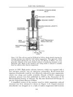
Papin’s engine. A small quantity of water in the cylinder is heated by an external
fire. The steam formed raises the piston to the top of the cylinder where a latch
engages a notch in the piston rod. The fire is removed and condensation
(perhaps assisted by an external water spray on the cylinder walls) of the steam
produces a vacuum below the piston, on removing the latch the piston is driven
downward by the atmospheric pressure. This raises a weight attached by a rope,
passing over a pulley, to the piston rod. The cycle may be repeated.
Newcomen’s engine. Steam passes from the boiler through a valve into the
cylinder, this balances the atmospheric pressure on the upper side of the piston
and allows the weight of the pump rod, connected to the piston rod by a beam
balanced on a fulcrum, to raise the piston. The valve between the boiler and the
cylinder is closed and a jet of water is sprayed into the cylinder. This produces a
vacuum by condensing the steam, so the atmospheric pressure on the upper side
of this piston forces it downward, lifting the pump-rod by means of the beam.
The cycle may be repeated. See also Figure 6, p. 34.
Watt’s engine. Steam is admitted, through a valve, into the steam case surrounding
the cylinder. The separate condenser is then connected to the cylinder, the
condensation of the steam produces a vacuum and the pressure of the steam in the
steam case acts on the upper side of the piston and forces it downward. When the
piston reaches the base of the cylinder, a valve is opened that equilibriates the
pressure on either side of the piston so the weight of the pump rod, acting through
the beam and piston rod, raises the piston. The cycle is then repeated.
Reproduced with permission from H.W.Dickinson A Short History of the Steam
Engine, 2nd edn (Cass, London, 1963).
Figure 5.1: Schematic arrangements of the steam engines of Papin, Newcomen,
and Watt.
STEAM AND INTERNAL COMBUSTION ENGINES
275
Newcomen’s engine
The practical steam engine (Figure 5.1) was introduced in 1712 by Thomas
Newcomen. A crucial element of this machine was the overhead beam, which
allowed mechanical effort to be obtained from the engine. Other important
features were: (a) a jet of water to condense the steam inside the cylinder,
which would increase engine speed by decreasing the time required for
condensation; (b) valve gear that makes the engine self-acting (the second
example, after the clock escapement, of a self-acting device).
The first Newcomen engine was erected in 1712 to operate a mine drainage
pump near Dudley Castle in Staffordshire (see p. 34). The subsequent
chronology of Newcomen engine erection is impossible to determine with
certainty, but engines were erected in Britain and on the European continent
chiefly for water pumping (mine drainage, recovery of flooded land, emptying
dry docks, water supply etc.). They were built by various engineers, many
English, operating under licence from a committee of proprietors who owned
the master patent (originally belonging to Savery).
Watt’s engine
In 1764, James Watt, the most significant figure in the history of the steam
engine, was employed as an instrument maker and was retained to repair a
model Newcomen engine owned by the University of Glasgow. He noted the
high internal energy of steam compared to liquid water (a ratio of about 6:1
for the conditions in Watt’s model engine), which demonstrated to him its
great economic value and the need to conserve its internal energy. Accordingly,
Watt insulated the boiler and steam pipes, and applied a steam jacket to the
engine cylinder. However, he quickly appreciated that even more significant
losses occurred, namely: (a) energy lost in cooling the piston and cylinder
when water was sprayed into the cylinder to produce condensation and a
vacuum; (b) loss of power due to the pressure of vapour below the piston as a
consequence of incomplete condensation.
He realized that these losses could be avoided if condensation was carried
out in a separate chamber that was connected to the engine cylinder (see
Figure 5.1). Immediately, in May 1765, he built an improvised engine, using a
large (44mm (1.75 inch) diameter by 254mm (10 inch) long) brass surgeon’s
syringe, to demonstrate the correctness of his ideas. Two other models (1765,
1768) were built, and in 1768 Watt applied for a patent. A fourth, much larger
(450mm (18 inch) stroke by 1500mm (5 feet) bore), engine was built with the
financial assistance of Dr John Roebuck at Kinneil, Scotland, probably in 1769.
In 1768, following a visit to London to obtain his patent, Watt met Matthew
Boulton, a Birmingham manufacturer, owner of the Soho Foundry. Boulton
PART TWO: POWER AND ENGINEERING
276
was immediately interested in Watt’s invention and in 1769 the two became
partners (although Watt did not move to Birmingham until 1774). The
combination of Watt’s scientific and engineering talents, the business acumen
of Boulton, and the compatability of their personalities ensured the success of
the partnership and of Watt’s engine.
Interest in Watt’s engine among engineers concerned with mine drainage
and water supply was immediate, both because of Boulton’s reputation for
sagacity and because of its manifestly superior efficiency and higher speed
compared to the Newcomen engine. However, engines of the latter type
continued to be built for many years after Boulton and Watt commenced
manufacture in 1774.
The initial application of the Watt engine was to mine pumping, but
Boulton recognized that there was a large market for engines that could drive
mill machinery. This required a rotary output from the engine.
On 25 October 1781, Watt obtained patent on his sun-and-planet gears
that provided a rotary output from the engine without the use of a crank.
Watt wanted to avoid the use of a crank which is the obvious, and
currently conventional, method of achieving his objective, not, as tradition
has it, because others had patented this device (in fact, Watt considered it
unpatentable because of its prior application in the foot lathe by an
unknown person), but because he did not wish to become involved in
lawsuits that might overthrow his 1781 patent or others he owned. This
could have happened if patents owned by Matthew Wasbrough and James
Pickard, which had employed the crank, without patenting it, as part of
various mechanisms to convert reciprocating to rotary motion, had been
declared invalid.
While the sun-and-planet gear will in principle convert reciprocating motion
to rotary motion it produces a very irregular speed at the engine output when
combined with the single-acting single cylinder engine. The double-acting
engine, in which steam is supplied to both sides of the piston, is essential for
uniform speed. This was covered by a patent issued to Watt on 17 July 1782
(the patent was also concerned with the expansive use of steam and a rotary
engine). The first double-acting engine was built in 1783 for John Wilkinson,
and another for the Albion Flour Mill, London, in 1784.
The double-acting engine requires a rigid connection between the piston rod
and the oscillating beam that transmits the power from the cylinder to the
engine output, in order to transmit the piston thrust on its upward stroke. In
June 1784, Watt devised a suitable mechanism called by Hartenberg the
‘perpendicular motion’. This particular linkage had the disadvantage that it
lengthened the engine by about half a beam-length, so only two engines were
fitted with this arrangement. Watt then devised the so-called ‘parallel motion’,
which connects the end of the beam to the piston rod by a pantograph. So,
nearly three-quarters of a century after Newcomen built his first engine, the
STEAM AND INTERNAL COMBUSTION ENGINES
277
steam engine was able to provide a rotary output, but, more than that, because
it was now of necessity double-acting, its power output had doubled.
1800–1850: new types of engines
In 1800, Watt’s patents expired, opening the way for the development of new
types of engines. These can be broadly classified into three groups. First, the
high pressure engines, in which the boiler pressure was increased above the
0.34bar (5psig) used in the Watt engines, and exhaust was to the atmosphere
instead of into a condenser. The second type was the Cornish engine, which
was essentially a non-condensing Watt pumping engine. The third group (not
described because of space limitations) comprises those engines that cannot be
classed as high pressure or as Cornish engines.
The high pressure engine
High pressure non-condensing engines appear to have been first proposed in
1725 by Jacob Leupold of Leipzig. Watt, as well as his assistant William
Murdock, also considered the concept. The advantages of this type of engine
are: (a) it can operate at a higher speed because there is no need to allow time
for the condensation process to occur; (b) the valve gear is simpler than that of
the atmospheric engine; (c) the dimensions for a given piston force are
independent of the atmospheric pressure, so the higher the boiler pressure the
smaller the piston diameter; (d) the engine is easy to work because of its simple
valve gear, and because there is no longer any need for constant vigilance over
the condenser; (e) because of its light weight and small size the engine is low in
manufacturing and installation costs. Disadvantages of the high pressure
engine are: (a) it is of lower efficiency than its condensing counterpart, but this
could well be of secondary importance where fuel is cheap (e.g. at a coal
mine); (b) at the beginning of the nineteenth century boilers suitable for
operating 34bar (50psig) did not exist.
The first engineers to build and operate successful high pressure engines
were Richard Trevithick, a Cornish mining engineer, in 1798, and Oliver
Evans in the United States in 1804.
The Cornish engine
The high pressure engine entered into engineering practice by way of the
lowspeed Cornish engine rather than the high-speed engine of Trevithick and
Evans, although Trevithick was intimately connected with the development of
PART TWO: POWER AND ENGINEERING
278
the Cornish engine. This engine was essentially a non-condensing Watt
engine, operated expansively, and supplied with steam at a higher pressure
than the 0.34bar (5psig) favoured by Watt. It had a profound effect on the
history of the steam engine because it demonstrated the possibilities of the high
pressure, non-condensing engine as an efficient prime mover. Its immediate
impact was in the mines of Cornwall where, following the installation of the
first Cornish engine by Trevithick in 1812 at the Wheal Prosper mine, the
reported average thermal efficiency of pumping engines increased more than
three times between 1814 and 1842.
This ever-improving performance attracted the attention of engineers
elsewhere, and in 1840 a Cornish pumping engine was installed at the Old
Ford Water Works of the East London Waterworks Company. A slightly
smaller Boulton and Watt engine was also placed in service at the same site
with the intention of comparing the performance of the two engines. Tests
showed that the Cornish engine was more than twice as efficient as the
Boulton and Watt engine. Consequently, the use of Cornish engines spread to
other water supply companies and mines.
The power output of any non-condensing steam engine (or steam turbine) can
only be increased by raising the boiler pressure. Because of the direct relationship
between steam density and pressure, the mass of steam admitted to an engine
cylinder of a given size will increase as the boiler pressure increases. Consequently,
with ever-increasing boiler pressure larger and larger volumes of steam have to be
accommodated in the cylinder at the end of the piston stroke. If the cylinder is of
fixed size it may not be possible to expand the steam to atmospheric pressure, with
a resulting loss of energy. To avoid this waste, the engine cylinder can be increased
in size, but there is a practical limit to this, fixed by manufacturing facilities and
means of transporting the massive cylinder, and this had been reached by 1850
when Cornish engines with cylinder bores in excess of 2540mm (100 inches) and
strokes longer than 3000mm (10 feet) were being constructed. The only way to
avoid this situation was to carry out the expansion in two or more cylinders: that
is, the compound had to be introduced.
The compound engine
In the compound engine the steam supplied by the boiler is expanded to the
exhaust pressure by passing successively through a number of cylinders,
where each cylinder operates between decreasing inlet and outlet pressures
(see Figure 5.2).
The compound engine was patented by Jonathan Hornblower in 1781 in an
attempt to avoid the Watt patent. He erected the first one at Radstock Colliery,
near Bristol, in 1782 and a second in 1790 at the Tincroft Mine in Cornwall.
Neither engine was superior to the contemporary simple (non-compound),
STEAM AND INTERNAL COMBUSTION ENGINES
279
atmospheric engines, because the boiler pressure (0.34bar, 5psig) then in use
was too low to justify the application of the compound principle.
The first engine to realize some of the theoretical advantages of
compounding was an existing simple engine that was modified in about 1803
by the addition of a cylinder by Arthur Woolf. Probably Woolf was aware of
Hornblower’s work with compounding because he was employed by the latter
in erecting steam engines. He appreciated that high pressures were essential to
the successful operation of a compound engine, and in its final form his engine
incorporated a cast-iron high pressure boiler that produced steam at about
3.1bar (45psig). Unfortunately, Woolf employed completely incorrect cylinder
proportions in designing his engine, but apparently it worked well enough to
convince him and his employers, a London brewery, that a larger engine
should be built. This was completed in 1805 (HP: 203mm (8 inch)
bore×914mm (36 inch) stroke; LP: 762mm (30 inch) bore×1524mm (5 feet)
stroke; boiler pressure 2.8bar/40psig), but it was unable to produce its design
power output of 27kW (36hp). Woolf, in consequence, left the brewery, and
went into partnership with Humphrey Edwards, and by 1811 he had
apparently obtained a satisfactory design for his compound engine.
The partnership between Edwards and Woolf was dissolved in 1811 and
Edwards emigrated to France. There he built Woolf compound engines and
sold them throughout Europe. The Woolf compound engine was characterized
by having the cranks on the high and low pressure cylinders set at 180°.
In spite of the success of the Woolf engine on the Continent, the compound
engine did not reappear in Britain until 1845, when William McNaught
patented an arrangement where a high pressure cylinder was added to an
existing beam engine in order to increase its power output. This system was
widely employed to increase the power output of stationary engines and was
known as McNaughting.
1850–1900: the steam engine in its final form
By 1850 the steam engine was a well-established machine, in which the
particular forms most suitable for each application had been identified, and in
which the manufacturing techniques and tools to ensure reliable operation had
been established. In the second half of the nineteenth century the emphasis in
steam engine development and design was on techniques for improving the
efficiency of the engine, on increasing the crankshaft speed, and on ensuring
the maintenance of a steady speed. High efficiency was particularly important
in marine engines (see Chapter 10). A high and uniform speed was important
in driving textile mill machinery (see Chapter 17), and in electric power
generation, which spread rapidly after Edison began operating the Pearl Street
generating station in New York in 1881 (see Chapter 6).
PART TWO: POWER AND ENGINEERING
280
Figure 5.2: The multiple expansion steam engine.
(a) Tandem compound engine. This works on the Woolf principle with steam
passing directly from the high pressure (HP) cylinder to the low pressure (LP)
cylinder during the whole stroke. A receiver is not required between the HP and
LP cylinders because the cylinder events are appropriately synchronized.
(b) Compound engine with side-by-side cylinders. The arrangement shown has
cranks at 90°. This makes the engine easier to start and to reverse than one
STEAM AND INTERNAL COMBUSTION ENGINES
281
working on the Woolf principle with cranks at 180°. However, a steam
receiver must be placed between the HP and LP cylinders because of the
relative order of events in the two cylinders.
(c) Side elevation of (b).
(d) Three crank triple expansion engine. Note the use of a piston valve
on the high pressure (HP) cylinder, and slide valves on the intermediate
pressure (IP) and low pressure (LP) cylinders. Cranks would usually be
set at 120° and receivers would be placed between each stage of
expansion.
(e) Four-crank triple expansion engine. The low pressure (LP) expansion
is divided between two cylinders in order to avoid a low pressure
cylinder of impracticably large diameter.
(f) Plan view of (e). Note the pipes connecting the various stages of
expansion are sufficiently large in this case to act as receivers.
Reproduced with permission from: W.J.Goudie, Ripper’s Steam Engine
Theory and Practice, 8th edn (London, Longmans, Green, 1932).
The beam engine, except for a few special cases, disappeared between
1850 and 1870 with the increasing adoption of the crosshead (possibly
introduced by Trevithick in his high pressure engine, above) for converting
reciprocating motion into rotary motion. The most notable application of the
beam engine during this period was in American river and coastal
steamships, where it was known as a walking beam engine. Engines of this
type continued to be built for this purpose until the late 1880s. As an
example of the sizes attained, the Long Island Sound steamship Puritan,
launched in 1889, used a compound beam engine of 5600kW (7500hp)
output with cylinders of 1900mm (75 inch) bore× 2700mm (106 inch)
stroke, and 2800mm (110 inch) bore×4300mm (14 feet) stroke. Beam type
pumping engines were built for water supply purposes in Europe until at
least 1878.
Automatic variable cut-off
Expansive working, in which steam is admitted to the cylinders only during
the first part of the piston stroke, is essential for maximum efficiency. This
type of operation is most effective if the point of steam supply cut-off is
related to the engine load. However, from the time of Watt variations in
engine load had been accommodated by adjusting the opening of the throttle
valve between the boiler and the engine which controlled the steam pressure
at inlet to the engine. In most cases (except steam locomotives) this was done
automatically by a governor, and the engine was then said to be throttle
governed. However, the energy lost (wire drawing) by the steam to overcome
the pressure drop in the throttle valve was no longer available to do work in
the cylinder.