An Encyclopedia of the History of Technology part 28 pot
Bạn đang xem bản rút gọn của tài liệu. Xem và tải ngay bản đầy đủ của tài liệu tại đây (293.44 KB, 10 trang )
PART TWO: POWER AND ENGINEERING
252
hauled up on to the carriage by means of a crane at the entrance end of the
carriage. The chain on the crane is wound up by a windlass driven by the sails
through the drive shafts of the carriage. The saw frames consist of double top
and bottom bars separated by about 25mm (1in). In this gap the saw ends are
slotted and are separated by amounts equal to the thickness of the timbers to
be cut. The saws are tensioned by wedges driven into sockets in the ends.
These saws are extremely powerful, and at d’Heesterboom, the smock saw mill
in Leiden, built in 1804 and still used, the wind-driven saws are used for logs
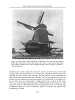
of 600mm (24in) or more in diameter. Figure 4.5 shows the paltrok ‘De
Poelenburg’ of 1869.
Figure 4.5: The paltrok ‘De Poelenburg’ at Zaandam. This saw mill was built in
1869. The brick base on which the whole mill rotates is visible behind the ladder
and winding windlass. The crane for lifting the logs onto the stage is on the left.
Anders Jespersen.
WATER, WIND AND ANIMAL POWER
253
The paper-making windmills are exemplified by De Schoolmeester at
Westzaan in North Holland, a thatched smock mill with a reefing stage, a tail
pole and windlass, where fine white paper is made from rags. The drive
comes from the cap right down to ground level where the machinery is
situated. The rags are sorted and cut by hand against fixed knives in order to
reduce the pieces to a manageable size. The rags are then chopped to finer
particles in a tub with a strong wooden bottom in which four knives on poles
are lifted and dropped by means of cams, and they are then soaked in a
caustic solution and placed in the ‘hollander’. The hollander is a long tub
with semicircular ends and a spine down the centre. On one side of the spine
the floor of the tub rises to meet the underside of a drum which is covered
with blades along its length and around the rim. The fluid of rags, chemicals
and water is pushed around the tub by the motion of the drum. As the fluid
passes under the drum, the blades reduce the rags to their constituent fibres.
The resultant fibres are then taken to the vats, where the vatman makes the
individual sheets of paper by hand. He takes a wire frame of gridded brass
wire, possibly with a pattern on it which becomes the watermark, shakes an
even layer of fibres on to his wire frame, lifts it out of the water and drains it.
He then flops the fibre out of the frame on to an adjacent sheet of felt, and
this is the basic material for one sheet of paper. The paper with its sheet of
felt is lifted on to a pile of felts which are gradually draining. The felts are
then put into a screw press to be reduced to the normal thickness of that
quality of paper. The screw is turned by hand until it needs more force to
make it go down further. At that point a horn is blown and all the staff of the
paper mill drop whatever they are doing and come to pull on a long lever
arm on the press. They may even be on a rope attached to the end of the
arm. They pull until the press is right down, the water has drained out, and
they have the sheets of paper between the felts. The pile is opened out and
the sheets are hung, one at a time, over cow-hair ropes (which do not stain)
to dry. This explains the presence of the long shed which extends to the base
of the windmill across the prevailing wind.
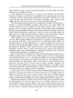
A third type of industrial windmill, the oil mill, is almost the only industrial
windmill known in England. The oil mill is usually a smock mill, and Het
Pink at Koog an de Zaan is a preserved example. See Figure 4.6. The drive
comes down from the cap to drive the machinery, which is so heavy that it
must stand at ground level. There are three wind-driven elements in the oil
mill: the kollergang (or roller crusher), the stamps and the heating plate. The
kollergang consists of two huge stone edge-runners which roll, on different
paths, around a circular stone base. The oil seed is put on this base and the
drive to the kollergang is engaged. The rollers turn ponderously round and
round on the base. The oil seeds are crushed while wooden rakes, fixed ahead
of the rollers, keep the seed in the tracks. The seed is then taken to the heating
plate where it is heated to release the oil. To circulate the heat the seeds are
PART TWO: POWER AND ENGINEERING
254
Figure 4.6: The cross section of a smock windmill for crushing oil seeds. The
stamps, kollergang and heating bowl are shown in this picture.
WATER, WIND AND ANIMAL POWER
255
turned over and over by an ‘S’-shaped blade rotating over the plate. The
heated seeds, releasing oil, are put in horse-hair pockets which are held in a
great wooden beam by blocks and wedges. Each block has a wooden stamp
above it which is raised and lowered by a cam which is driven from the upright
shaft. After the stamps have dropped a set number of times, a further stamp is
released which hits a reverse wedge, and this loosens the hair pockets and the
seed is lifted out. As the stamps and blocks squeeze the seed in the hair
pockets, so the oil runs out to be collected. The first pressing of oil is set to one
side before the crushed seed is subjected to the same process again.
John Smeaton designed a wind-driven oil mill at Wakefield. This is like the
Dutch oil mill, of which Smeaton was well aware, but has several refinements
which indicate the state of the windmill millwrights’ craft in the mid-eighteenth
century. Wakefield oil mill was completed in 1735 and was a smock mill on a
square brick base. The base consisted of two tall storeys containing all the
machinery, while the smock was a means of giving height to the sails and had
no floors or machinery in its height. The machinery consisted of a kollergang,
which was right in the centre of the mill so that the two rollers were turned by
the upright shaft without intermediate gearing, and to one side of this there
was the bank of stamps. In Smeaton’s design in the Royal Society Library
there is no hot plate shown, but this was certainly a requirement of this type of
mill, as it is needed in the cracking process. Above the first floor there are sack
hoists and hoppers. The other variation from conventional windmill design lies
in the sails, of which there were five, mounted on a cast-iron windshaft by
means of a cross, a series of flat channels into which the sail stocks are bolted.
The other way of mounting the sails is in a canister, or poll end, through
which the sail stocks are wedged. The shafts and gear wheels were all of wood
and only the windshaft was made of cast iron.
Eighteenth- and nineteenth-century innovations
Smeaton carried out experiments in watermill design (see p. 236) and his
curiosity also extended to improvements in windmills. There is a model of his
experimental design for windmills in the Science Museum in London. It is
interesting to note that the ‘weather’ detailed for the sails in his experiment is
the same as that shown in the diagram in the Groot Volkomen Moolenboek. Of
course other millwrights were working at the same time as Smeaton to improve
the efficiency of the windmill. Perhaps it is in the development of the sails that
the largest number of types and patents is found.
A common sail is one in which a sheet of canvas is stretched over a sail
frame. A common sail frame which is not clothed consists of square panels
formed by the laths and hemlaths over which is draped the rolled-up sail. At
the inner end of the sail there is a ‘curtain rod’ with rings on it to which the
PART TWO: POWER AND ENGINEERING
256
sail cloth end is fastened. All down the stocks there are cleats to which ropes in
the hems of the sail cloths are tied. The other edges of the sail cloths are tied
around the laths. At low windspeeds the sail is stretched out fully, but as the
windspeed increases, the area of the sail is reduced by making the sail cloth
dagger-shaped, with the point towards the tip. One great disadvantage of the
common sail is that the miller cannot set four sails at once; each sail has to be
brought to the ground, its cloth set, the brake released, and the next sail
brought into the vertical position. This cannot be hurried, and is a real
problem, or even a danger if a squall should develop suddenly: we can imagine
the miller’s horror if improperly braked sails started to turn while he was on
the bottom one.
Andrew Meikle, a famous Scottish millwright, produced the spring sail in
1772. In the spring sail, a number of hinged shutters made of wood and canvas
take the place of sail cloths. The shutters are all connected to each other by
means of a shutter bar running the length of the sail. The movement of the
bar, therefore, moves all the shutters open or closed together. The movement is
controlled by a spring at the tip of the sail which can be pre-set by means of a
slotted strap. As the wind blows, the tension in the spring causes the shutters
to open or close according to the wind pressure, letting the wind spill through
the openings and slowing the sail to the required speed. The disadvantage of
this arrangement is that the tensioning has to be done to a sail at a time when
it is stopped in the vertical position.
In 1789, Captain Stephen Hooper patented an automatic sail system which
is known today as the roller-reefing sail. In this type of sail a number of small
roller blinds replace the shutters of the spring sail. Each roller blind is attached
to the one above it and below it by means of webbing straps. The blinds are
connected to two wooden bars which run along the sail. The pressure of the
wind adjusts the extent to which the rollers open or close the sail. It was not a
great success, as too many parts could fail or decay. Sir William Cubitt, a
millwright and engineer, introduced his ‘patent sail’ in 1807, and this is the
shuttered sail most commonly met in England. The shutters, made of wood
and canvas, are interconnected as in the spring and roller-reefing sails, and all
their inner ends are connected by means of bell cranks to a ‘spider’ mounted in
front of the cross or canister. The windshaft is hollow and contains a rod,
called a striking rod, which projects from the back of the windshaft and is
joined to the spider at the front of the windshaft. At the rear, an endless chain
and a weight hang from a chain wheel on a pinion. The pinion engages with a
rack on the striking rod, and as the sails respond to the wind the weights
control the extent of opening to meet its pressure. This form of shutter is most
useful because it can be adjusted while the mill is running and without
stopping the sails.
On the continent of Europe, the shuttered sail in the English form is not
met with except in north Germany and Denmark, where it derives from
WATER, WIND AND ANIMAL POWER
257
English practice and millwrights. In the Netherlands there are some shuttered
sails in the north-east, near the German border, but most of the mills still
have cloth sails. There are several variations on sail forms, in particular in
the design of leading boards and stocks, but these are incidental to all the
processes of sail design. In France, the sail form most usually met with is the
Berton sail. In this the four sails are made of wooden slats set parallel to the
sail bars. The slats can open out or close according to the wind speed and
pressure. The controls run down inside the windshaft and can be adjusted by
the miller inside the cap according to the requirements of grinding and
windspeed.
Another contribution to ease the miller’s duties was the introduction of an
automatic means of turning the mill to face the prevailing wind (known as
winding and pronounced ‘win-ding’). In 1745, Edmund Lee patented a ‘Self-
Regulating Wind Machine’. The patent drawing shows a fantail geared down
to a ‘travelling wheel’ at the rear of the mill on the tail pole which moved
around the base of the tower and turned the cap when the fantail turned. By
modern standards this would have been ineffective, as the fantail was shielded
to a considerable extent by the body of the windmill. In 1782 John Smeaton
observed that…‘in this part of the country’ (Yorkshire, near his home) ‘it is a
common thing to put Sail Vanes that keep the mill constantly in the wind
without attention or trouble to the millman’. In 1782 he used a fantail in the
construction of a five-sailed windmill, Chimney Mills, Newcastle upon Tyne,
and this is thought to be his first use of this detail. The post mill could also be
winded in the same way, using a fantail mounted on the end of the tail pole or
ladder strings, and driving the wheels on a cast-iron track on the ground. This
system grew until the large Suffolk-pattern post mills, of which the preserved
mill at Saxtead Green is an example, reached the peak of efficiency and
performance. This type of post mill has a body mounted above a two-storey
roundhouse with the quarter bars at high level and a long ladder with a fantail
coming down to ground level.
The grinding of the hard wheat of the European prairies in Hungary
and elsewhere was a problem which was solved in Hungary in 1829 by the
invention of the roller mill. In this the grain was ground between successive
pairs of steel rollers in a continuous reduction process, being carried up the
mill by elevators between each grinding. The mill could be as big or as
small as capital would allow, since most of these mills were, from the start,
steam powered. The amount of grain ground even in the smallest plant
would be six times the amount ground between a pair of millstones. The
miller with a windmill could not compete with the roller mills because of
the uncertainties of his trade: low windspeeds on many days in the year,
and storm conditions when the mill would have to shut down completely.
The end came gradually, but by 1939 the demise of the windmill in Britain
was virtually complete.
PART TWO: POWER AND ENGINEERING
258
Wind engines and electric generators
In Britain a change in the form of the windmill took place and reached one or
two windmills: those at Haverhill and Boxford in Suffolk for example. This
was the annular sail. Here a ring of shutters is mounted at the tip of the sail
stocks and these provide the driving force to the windshaft instead of the
conventional sails. In the case of Boxford, there were 120 shutters in eight units
between eight stocks. By having all the shutters in the approximate position of
the tips of the conventional sails the greatest use can be made of the wind, for
it is at the uppermost tip that the work of the wind is most effective. Structural
difficulties prevented the conventional windmill from being adapted to take
annular sails: the pressure on the sail stocks would be greater, with more risk
of failure, for example. The originator of the Suffolk annular sail was Henry
Chopping. He built one at Richard Ruffle’s mill at Haverhill where the sails
were 14.6m (48ft) in diameter on a tower 20.1m (66ft) high.
Chopping had a provisional patent which he assigned to John Warner &
Sons of Cricklewood who were pump and machinery manufacturers—for
example they made a low-level horse-driven pump. They produced a pumping
wind engine which consisted of a skeletal tower carrying an
adjustableshuttered annular sail in which the shutters radiated from the centre
and were not in a ring at the outside of the diameter. Haverhill was equipped
with its annular sail in 1860–1, by which time annular-sailed windmills were
beginning to appear in the United States. (In American usage, the word
‘windmill’ has come to mean an annular-sailed windmill on a skeletal tower,
but in Britain the windmill is a post or tower mill with four sails. It is more
appropriate, therefore, to use the term ‘wind engine’ when referring to the
American version.)
The first commercially successful wind engines to appear in the United
States were invented in 1854 by Daniel Halladay of Marlbro, Vermont. He had
been in London in 1851 to visit the Great Exhibition in Hyde Park which had
such a great effect on the development of invention in both Europe and the
USA. Halladay worked on a wind engine which had self-reefing sails and
which was turned into the wind by a wind vane at the back so that it turned to
the wind like a weathercock. He quickly moved from paddle-shaped blades to
thin blades slotted into wooden rims. As the wind pressure varied, so the angle
of the vanes to the plane of their mounting varied. At low speeds the vanes
would be fully extended and flat with the face of the mounting, but at high
speeds the vanes would be at right angles to this face. There are many variants
in a whole series of adjustable-vaned wind engines, but the common American
wind engine which was quickly brought into being was one with fixed vanes
which met the variations in wind pressure by the way in which the tail vane,
held by a tensioned spring, turned the vanes away from the wind. This type of
wind engine was erected in tens of thousands all over the United States and in
WATER, WIND AND ANIMAL POWER
259
particular in the prairie states, and is still to be found in use. In the ranch
country, one duty of the cowboy was wind engine maintenance, a role which is
never part of his film image. One peculiar variant of the wind engine in the
United States was the creation of horizontal wind engines, such as the Gladden
Mill preserved in Randolph, New York.
In Europe, the wind engine followed the fixed-vane pattern common in the
United States, and perhaps the best-known British example is the Climax, built
in its thousands by Thomas of Worcester. This is a fixed-blade wind engine
with the gears encased in a box filled with lubricating oil. This oil-bath wind
engine was adapted by many manufacturers and was popular because
lubricating was reduced to a once-a-year task. In addition to the fixed-blade
wind engines several forms of adjustable-vaned or shuttered wind engines were
produced in England and in Europe. One particularly notable group of these,
produced by John Wallis Titt of Warminster, achieved a very large diameter—
up to 12.2m (40ft)—and were exported all over the world for water pumping.
In Germany and Denmark, several other types of shuttered wind engines were
produced, such as those of G.R.Herzog & Karl Reinsch of Dresden and Reuter
& Schumann of Kiel. Other experiments with wind engines saw a return to the
principles of the water turbine, in which the wind was focused by the fixed
non-rotating vanes of a stator on to the rotating vanes which represent the
rotor. One group of these wind engines was the invention of the Bollée family
of Le Mans, France, who also made pumps, steam cars and, later, automobiles.
While the majority of wind engines were used for pumping, they were also
used for conventional farm duties and to generate electricity. The wind engine
is now being examined seriously for the development of electric power and
water pumping. Perhaps the most famous of all the wind-driven generators
was that at Grandpa’s Knob in Vermont, which began to supply electricity on
19 October 1941. In a 40kph (25mph) wind it had settled down and was
producing 700kW (940hp). However, by 26 March 1945 it had failed
structurally. This was a two-blade windmill with adjustable aerofoil section
blades mounted in front of a generator housing on top of a heavy structure.
The two blades were 53.3m (175ft) from tip to tip on a 32.6m (107ft) high
tower. There were experiments going on at the same time in Britain, the Soviet
Union, Denmark and Germany with very big wind engines. A formidable
variant of this is the EnfieldAndrew 100kW (134hp) generator which was
erected in St Albans in Hertfordshire, following development of a prototype in
France. In this the 24m (79ft) diameter blades drew air through themselves at
considerable velocity and threw this out at their tips by centrifugal force. The
air was drawn up the tower through the turbine and generator from the
bottom. The advantage of this was that the turbine and generator were in the
fixed base of the machine, which eased the problem of getting the electricity
out of the generator. On other types of wind engine the generator rotates with
the crown and blades, making the supply of electricity very difficult.
PART TWO: POWER AND ENGINEERING
260
Since the mid-1970s the supply of electric-generating wind engines has
grown in Europe. In the southern Netherlands there are modern wind engines
around the towns, but because these are very new no one form has become
established as the most appropriate type. The conventional Dutch smock mill
has been used to generate electricity on the island of Texel, and several other
forms of wind generator derive from scientific studies which have been carried
out in Denmark and in the United States. One important example is at
Gedsermolen, on a cape in the south-east of Denmark, with a 24m (69ft)
diameter for three blades, and this and many other small examples are used to
power greenhouse sites, private houses and objects which can have no
attachments to power stations such as the lights on sea marks and buoys.
Research has also been under way in Europe to develop small wind engines
for use in the Third World. This work has been undertaken in many
universities and development centres and is successful in producing small
lowpowered pumps for irrigation and town water supplies. This is in some
way a logical development because the small unit is within the means of the
Third World, but the capital costs of large wind engines inhibit their
development as an alternative power source to oil or coal in the western world.
Wind power has a long history and it can go on contributing to the well-
being and needs of the world in many ways for the foreseeable future.
ANIMAL POWER
Classification
While animal power has made a significant contribution, it stands to one side
of the main stream of development. It may be true to say that in terms of the
development of power the use of animals as a power source came first.
Animal-powered machines fall into two categories: those in which the
animal is working in a vertical plane around a horizontal shaft, and those in
which the animal moves on a horizontal path around a vertical shaft. Within
these two classifications there are several types of animal-powered engine. The
vertical engine is the simplest classification, for in this there are only two types.
In the more important, the treadwheel, farm animals, or men, trod the inside
of the boarded rim of a wheel. The treadmill is a minor form in which men, or
more rarely animals, trod the outside of the rim of a wheel.
Horizontal animal-powered engines are far more varied and fall into several
types. The first division contains those machines which have a direct action,
i.e. there is no gearing between the animal and the work it does. One well-
known form of direct-action machine is the cider mill, in which a large edge-
runner stone rolls over the cider apples in a circular trough. The crushing of
ore or brick clay by a similar edge-runner mill is another form of the direct-
WATER, WIND AND ANIMAL POWER
261
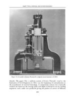
action animal machine. The ‘direct action’ designation can also be applied to
the horsedriven winding drum used in coal or ore mines. In this engine a
large-diameter drum is mounted at the head of a vertical shaft, and underneath
this a horse arm is mounted to which one or two horses can be harnessed. As
the horses walk in a circle so the cage, or kibble, is drawn up out of the mine
shaft. This type of machine often has two cages so that by working on a one-
up one-down principle, the weight of the cage and the rope is counterbalanced
(see Figure 4.7).
In the second division there is a train of gears between the motion of the
animal and the work it does. The geared machine was used for an even
greater number of agricultural and industrial purposes, and there are two
types of these. The older type is one in which a large-diameter gear wheel is
mounted on a vertical shaft at high level above the height of a horse. The
horse is harnessed inside the circumference of the wheel or outside it,
according to the diameter of the gear wheel. The gear wheel engages with a
second gear on a lay shaft which takes the power from the ‘horse wheel’ to
drive other machinery by means of further gears or pulley belts. The later
type, which was really only made possible by the universal use of cast iron
for gearing and machinery design, is the low-level machine, in which a small
gear wheel is encased in a frame from which the vertical shaft rises to be
harnessed to the horse. The animal has to step over the gear shaft which
runs at ground level from the engine in the centre of the horse path to the
Figure 4.7: A two-horse winding engine for a colliery. This illustration from
Pyne’s Microcosm of 1803 is of a one-up one-down arrangement.