An Encyclopedia of the History of Technology part 27 docx
Bạn đang xem bản rút gọn của tài liệu. Xem và tải ngay bản đầy đủ của tài liệu tại đây (131.67 KB, 10 trang )
PART TWO: POWER AND ENGINEERING
242
the sole, the air was forced out of the bucket and the water filled it properly.
Fairbairn was also responsible for the introduction of a workable system of
governors to control the flow of water through the hatches and on to the
waterwheel, and by using a shaped series of slots in the hatch a smoother flow
of water was delivered to the buckets.
William Fairbairn was knighted for his engineering work, and was
recognized for his scientific approach to structures by being elected a Fellow of
the Royal Society. His book Treatise on Mills and Millwork, first published in
1863, became the classic text-book in Britain on the construction of these
‘modern’ waterwheels. On the continent of Europe, Armengaud the elder
published his Moteurs Hydrauliques in 1869, Heinrich Henne his Die Wasserräder
und Turbinen in 1899, and Willhelm Müller his Die eisernen Wasserräder in 1899,
while in the United States, Practical Hints on Mill Building by James Abernathy,
published in 1880, was of great importance. By 1900 the emphasis on water
power was switching from large, efficient waterwheels to the smaller and even
more efficient water turbine.
WATER TURBINES
In France, the design of waterwheels had been given considerable attention at
the beginning of the nineteenth century, but there was always a search for
greater efficiency. J.V.Poncelet had taken the old form of vertical undershot
waterwheel which had straight blades or floats made of wood and set radially,
and by curving the blades and constructing them of metal, had produced much
greater efficiency. By using tight-fitting masonry walls and floors in the wheel
pits, he ensured that all the water would be swept into the space between the
blades. He used formulae to determine the size of the floats in relation to the
wheel and the water flow. A further vital point, particularly with an undershot
wheel, was that the water flowing out of the floats fell clear of the wheel so that
it did not run in tail water. This interest in waterwheel performance led to the
first viable turbine designs being produced in France: it is significant that the
south of France, Spain and Portugal had large numbers of water-driven corn
mills in which the waterwheel ran horizontally, often forced round by a jet of
water. Benoît Fourneyron produced a successful water turbine in 1827, and the
design of other water turbines was proceeding in Germany and in the United
States, but not in Britain where the waterwheel designs were reaching their
peak. The Fourneyron turbine consisted of an inner fixed ring of curved gates
set in one direction, and an outer ring, which had curved blades set in the
opposite direction, mounted on the drive shaft of the mill or factory. The water
flowing into the fixed ring was controlled by a circular iron hatch which
moved up and down in the water to control the flow. The water flowed over
the gate and through the fixed gates to impinge on the rotating outer ring of
WATER, WIND AND ANIMAL POWER
243
blades, and thereby revolve it at a considerable speed; thus a small turbine
could produce more power at greater speed, using less space than the
equivalent waterwheel. The Macadam brothers of Belfast, Northern Ireland,
produced a very efficient version of the Fourneyron turbine, of which the
preserved example from Catteshall paper mill in Godalming, Surrey, is typical.
The stator (fixed inner ring) and rotor (rotating outer ring) each have forty-
eight vanes, and the inside of the stator is 2.5m (8ft 3in) in diameter. The
Catteshall turbine developed 37kW (49.6hp) at approximately 25rpm, and in
1870, when it was built, it was among the biggest then in use. The principle of
the Fourneyron is that of an outwardflow reaction turbine.
In England, between 1734 and 1744, an invention called the Barker’s Mill
was introduced. In this water is led into a vertical tube, which rotates, and at
the bottom of this tube two arms project which have nozzles at their tips. As
the water flows, so the jets spout out at the ends of the arms, and the whole is
pushed round by the reaction of the jets against the pressure of the air. While
one or two examples of this are known, such as that at the Hacienda Buena
Vista at Ponce, in Puerto Rico, it must have been hopelessly inefficient. James
Whitelaw took the principle of the Barker’s Mill, improved the shape of the
arms and introduced the water from below, to give a much more efficient
machine known as the Scotch turbine. The arms were in the form of an
elongated ‘S’ with the inlet pipe in the centre. The new shape induced a better
flow out of the nozzles at the ends of the arms. The Whitelaw turbine had
governors to control the speed of rotation. After 1833, when Whitelaw built
his prototype, several of these were installed in factories in Scotland. One
example is quoted as having 1491.4kW (200hp) with a fall of 6.7m (22ft) and
a speed of 48rpm. Escher Wyss & Co. of Zurich installed Whitelaw turbines in
1844, and these were up to 45kW (60hp).
James Thomson trained as an engineer in the works of Sir William Fairbairn
and became a professor in Belfast. In 1846 he was at work on the design of a new
form of turbine which, when tested in 1847, worked at one-tenth of a horse power
at an efficiency of some 70 per cent. He went on to patent this turbine in December
1850. Described by its inventor as a Vortex turbine, it was an inwardflow turbine
in which the water came into the casing and was taken through a spiral path to be
discharged through gates on to the rotor. At the same time J.B. Francis was
working on a similar arrangement in Lowell, Massachusetts, which he called a
centre-vent turbine. His work was published in Lowell Hydraulic Experiments. He was
associated with Uriah A.Boyden in producing the Boyden turbine which was an
adapted Fourneyron, designed for the particular needs of the Lowell cotton mills,
and the horse-power results were extremely good. In 1854, the Merrimack
Company’s mills had Boyden turbines of 2.75m (9ft) diameter which generated
522kW (700hp) under a 10m (33ft) head.
Meanwhile, the development of other turbines was proceeding in France,
owing to a lack of coal to power steam engines, and in Switzerland and
PART TWO: POWER AND ENGINEERING
244
Germany. The ability to use a high head of water, as one would get in
Switzerland or Germany, led to the design of other forms of turbine. The most
famous of these high-head turbines, requiring only a small flow, is the Pelton
wheel. This is an impulse wheel, patented in 1880, in which a jet of water is
focused on to a bucket on the diameter of a small wheel. The bucket is cast in
the form of two cups which receive water equally when it comes out of a jet at
a tangent to the wheel. The water is turned back on itself as the bucket moves
forward. The Pelton wheel can achieve high speeds and is easily controlled by
the amount of water allowed out of the nozzle which opens or closes the size of
the jet. On the Coniston Fells in Cumbria there was a Pelton wheel made by
Schram and Marker of London, 0.6m (2ft) in diameter with approximately a
150m (500ft) head, which drove the air compressor in the slate quarries high
up on the fell.
Hydro-electric power
Professor Thomson’s first English turbine, made for him by Williamson
Brothers of Kendal in 1856, was a 3.73kW (5hp) Vortex made for a farm.
(This turbine, Williamson No. 1, can be seen in the Museum of Lakeland Life
and Industry in Kendal.) In 1880 this firm supplied their 428th turbine to Sir
William Armstrong of Cragside, Northumberland. Here Armstrong, himself a
prominent engineer, installed the turbine on an 8.8m (29ft) head of water to
evelop 9hp, transmitted by belt to a 90V dynamo from which Cragside was lit
by Swan’s electric lighting (see Chapter 6). This was the first hydro-electric
plant in Britain. In 1884, W.Günther of Oldham built his turbine number
twelve, a ‘Girard’ impulse turbine of 30kW (40hp), which was used for the
electric lighting of Greenock, Scotland.
Although factories continued to require turbines to power their machinery,
the main demand for water turbines lay in the production of hydro-electric
power. Turbines grew bigger, more efficient, and increased in horse power to
meet the growing demand for electricity in hilly countries where coal was not
available. The upper Rhine, between Basel and Strasbourg, has eight
hydroelectric stations, the dams of which make the river fully navigable to
Basel all the year round. Kems, built in 1932, is the oldest of this series, with
six turbines each developing 18.6MW (25,000hp) on a 16.5m (54ft) head. The
whole suite of hydro-electric stations between Basel and Strasbourg can
produce 895MW (1,200,000hp). Similarly, the Tennessee Valley Authority
(TVA) water control requirements enabled the Federal Government of the
United States to build a series of dams with hydro-electric plant in the years of
the Roosevelt ‘New Deal’, and in the immediate post-war years. The basic
turbine type for most of the high-powered hydro-electric plant has been the
Kaplan. This is a reaction turbine which uses a large flow on a low head, and
WATER, WIND AND ANIMAL POWER
245
which is made like a ship’s propeller with variable pitch vanes running in a
close-fitting casing. Victor Kaplan patented his turbine before the First World
War in Brno, Czechoslovakia, but it was neglected until the 1920s. These
turbines have been capable of some 85 per cent efficiency, and modern
developments in their design have made them even more efficient.
Perhaps the most impressive use of the Kaplan derivatives is in the great
tidal-power system of the Rance estuary by St Malo in France. This scheme
was completed in 1966 and presents many additional factors. As turbines they
must work on a variable head yet give a constant speed. Thus the Rance
design must represent the most flexible of all turbine solutions. It is interesting
to note that, in the new proposals to use the flow of the tides in areas such as
the Bay of Fundy in the United States, and the Severn estuary and Morecambe
Bay in England, there is a harnessing of a water-power source first used in the
late twelfth century in England.
Water power has been harnessed to great effect for 2000 years to provide
power for the many requirements of life. It started in order to ease the grinding
of grain for food, and grew to power all man’s industrial needs before steam
came into use as the power behind the burst of development which we know
as the Industrial Revolution. It is developing again to provide electricity on a
huge scale, as well as being used as a means of giving minor industrial
development to the Third World.
WIND POWER
The ancient world
While there is some certainty about the timescale and geographical distribution
of the water-powered corn mill in antiquity, there is far less knowledge about the
geographical spread of windmills. Given that the grinding of grain took place
between a pair of quern stones which rotated in a horizontal plane, then it would
seem to be easy to accept that the upper (runner) millstone could be fixed at the
bottom of a vertical shaft which could be turned mechanically. If that shaft were
to be of a fair length, and if it had sails attached parallel to it, then these could be
blown round by the wind. The problem is, of course, that the sails present the
same area of face to the wind as they are blown by it and as they come towards
it. This would seem to create equilibrium and prevent the mill from turning. We
are fortunate to have survivors of such very primitive horizontal windmills at
Neh, in the area of eastern Iran which is near the Afghan border. Here there are
rows of these mills built together to economize on the construction of the
supporting walls. The arrangement of a typical windmill in this area is that two
walls are built, some 6m (20ft) high, on top of a roofed mill room containing the
single pair of millstones. The shaft from the runner millstone rises through the
PART TWO: POWER AND ENGINEERING
246
roof of the mill room to a bearing in a beam between the tops of the two walls.
On the side facing the prevailing wind a wall is built up to the top of the two
walls but only across half the space between them. The wind, its force
concentrated by being funnelled through the row of narrow openings, turns the
shaft by means of the six or eight sails mounted on it. These sails are made of
wooden slats or reed mats fixed to the five or six sets of spokes on the shaft. As
the sails turn, the lee surfaces are never opposed by the wind because of the
protective wall. These windmills were first recorded in use in AD 644 in a
Persian manuscript of the early tenth century, but it is thought that they may
have existed in Egypt at the time of Moses.
The Persian horizontal windmill appears to have remained a static concept,
unchanged to the present day. What is missing is the link to the Mediterranean
windmill which is thought to be the precursor of all our vertical windmills.
The Mediterranean windmill is a two-storeyed stone tower mill with one pair
of millstones driven from the windshaft. The wooden windshaft projects
beyond the face of the tower and carries six, eight or twelve triangular cloth
sails which are set like jib sails from the sail stock to the opposite sail stock.
Indeed, the vertical windmill used in Europe may be a quite independent
innovation which derives from the Vitruvian arrangement of the water-
powered corn mill and not from the Persian windmill. The arrangement of the
drive in a vertical windmill is that the nearly-horizontal shaft through the sails,
which turn in a vertical plane, has a gear wheel mounted on it which engages
with a second gear wheel on the drive shaft of the runner millstone. It we
substitute the windmill sails of this concept by a waterwheel, we can see the
validity of the argument to support the lack of a technological link between the
Persian horizontal windmill and the European vertical windmill.
Mediaeval and Renaissance Europe
There were windmills in England in the years just before AD 1200. The
charters of St Mary’s Abbey at Swineshead in Lincolnshire give ownership of a
windmill there in 1179, and at Weedley in Yorkshire there was also evidence of
a windmill. Pope Celestine III ruled that windmills should pay tithes, so the
use of the windmill would seem to have been well established if they were
worthy of concern over their tax and tithe dues. The windmill was therefore
well established in northern Europe by the end of the thirteenth century, and
had an advantage in that it did not freeze up in winter as the watermill was
prone to do.
One great problem with the windmill in Europe is that the wind has no
prevailing direction as it clearly has in Persia. This means that the windmill
must always face the wind and that the wind must never be presented to the
back of the mill. The post mill would appear to be the first type of windmill to
WATER, WIND AND ANIMAL POWER
247
do this, and is the type of which we have the largest number of windmill
illustrations from the Middle Ages.
The post mill in the mediaeval period was probably quite small and simply
arranged. Stained glass and documentary representations show considerable
variation in form and construction, much of which must be discounted as
fanciful, but enough remains for the mill student to be able to learn the form of
the early windmill. All post mills consist of a wooden body, known in England
as the buck, which carries the sails, the windshaft, the gears and the millstones.
This can be turned into the wind, because it is pivoted about the top of the
king post. The mill body is heavy, and as it should not be backwinded, it is
fitted with a tail pole coming out of the back of the bottom storey of the body.
The miller puts his back to the tail pole and pushes it round when there is a
variation in the wind direction. The king post could not be a single post as it
would blow over, but would have to be propped by other timbers to give a
broad base to prevent the whole mill being overturned. Archaeological
excavation, such as that at Great Linford in Buckinghamshire, shows the
horizontal crosstrees which had the king post at their centre and the diagonal
quarter bars at their ends which provide the props to the king post. This frame
of the crosstrees, quarter bars and king post is so made that it is a rigid entity
which sits either on a cross of masonry on the ground, or on four pillars at the
ends of the crosstrees.
Post mills are shown in several mediaeval documents and in the illustrations
in the margins of manuscripts. From these we can see that the mill was small:
probably only big enough to house one pair of millstones with space over them
for the windshaft, brake wheel and gears on the runner millstone spindle. The
body would be suspended one floor up on the king post propped by the
quarter bars. In the picture in the fourteenth-century Decretals of Pope Gregory IX
the mediaeval post mill is properly understood, for here the post is seen to go
up to the underside of the second level within the body. Clearly, the body
cannot just sit on top of the post, for it must have some lateral hold on the post
where it passes through the framing of its bottom floor.
The sails of these primitive post mills were made of a frame of laths over
which cloth was stretched and tied in place. The sails were short, stretching to
the ground so that the miller could set the sails on the sail frame, and climb up
the frame if he wanted to remove the sail cloth completely. To adjust to
variable wind speeds he would set less sail, and he was possibly aware that by
adjusting the space between the millstones he would also meet the problems
associated with variable wind speeds. The windshaft (holding the sails) may or
may not have been inclined so that the plane of the sails was tipped slightly
backwards. A refinement such as that, which made for better balance in the
sails and windshaft and stopped a tendency to tip forward, is clearly a matter
of empirical knowledge. The gears would be heavy cog and rung gears, and
the method of braking is unknown; possibly the miller turned the mill out of
PART TWO: POWER AND ENGINEERING
248
the wind in order to stop it. No storage was available in this early post mill and
probably none was needed, because the mill would certainly have been held by
a landlord, such as a manor or an abbey, and the miller would be an employee
or a tenant operating under the milling soke and receiving his payment, or
multure, by removing a proportion of the meal.
Tower mills followed the post mill and appear to be shown in pictures and in
stained glass from the fifteenth century. In the tower mill only the cap and sails
rotate to face the wind while the mill body remains stationary. The principal
advantages of the tower mill over the post mill are in its stability and in the fact
that the portion to be turned to the wind is so much lighter. The cap is built up
on a frame which has a beam under the neck bearing supporting the front end of
the windshaft. The rear of the frame is usually extended to support a tail pole
which goes down to ground level. When the sails are turned to face the wind the
miller pushes the tail pole, and the cap, windshaft, sails and brake wheel turn.
The turning is usually achieved by the frame being supported on rollers or
sliders on top of a rigid circular track on the top of the tower.
The post mills of the Renaissance period are quite accurately depicted by artists
such as Brueghel the Elder. The picture known as The Misanthrope, painted in 1568,
shows a post mill very like those to be seen today in the Low Countries. This has a
tallish body on a post and quarter bars, with a ladder and tail pole at the rear and
four sails. An even more acceptable representation is the picture in the National
Gallery, London, A Windmill by a River, which was painted by Jan van Goyen in
1642. Here the post mill stands on a tall frame of multiple quarter bars on tall brick
posts, and has the steep tail ladder which characterizes many Dutch post mills.
The tower mill depicted in The Mill at Wijk bij Durstede by Jacob van Ruisdael,
shows a vertically-sided tower mill with a reefing stage, from which the cloth sails
were set, and to which the strutted tail pole extended. By the time this was painted,
about 1670, the windmill for grinding corn had become a much larger building. In
the case of the post mill, it could well be built so that there were two pairs of
millstones, each driven off the windshaft by its own set of gears. The tower mill
would be made bigger in diameter and taller, with a storage floor at the top of the
mill, and then, with the use of a great spur wheel and stone nuts, there could be
more pairs of millstones on the stone floor.
Dutch mills and millwrights
The Netherlands were situated well below sea level throughout the early
mediaeval period. It was a country beset by continual flooding, of which the
floods of 18 and 19 November 1421 were perhaps the worst, when seventy-two
villages were destroyed. Sea defences were constructed to keep out the sea flood
water; solid land was formed by draining the spaces between these sea dykes;
residual pools and lakes remained to be emptied; and windmills were brought in
WATER, WIND AND ANIMAL POWER
249
for this purpose. When the polders were dry it became necessary to retain the
windmills to drain the rainwater off the land and keep a level water table.
The first drainage mills were a variant of the post mill. The drainage was
carried out by scoop wheels, i.e. wateiwheels in reverse, at ground level. The
problem was to get the drive from the sails down to the scoop at ground level
when they were, in fact, separated by the buck and the post. The hollow post
mill was created to solve that problem. Here the drive is taken down through
the centre of the post, which is made up of four pieces, to gears at ground level
which turn the drive at right angles to power the scoop wheel. This hollow
post mill, Wipmolen in Dutch, was small but efficient and can still be found on
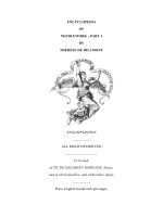
many of the polders. A version of the drainage wip mill, using cylinder pumps
instead of scoops, is illustrated in Figure 4.4. The tower drainage mill was
Figure 4.4: A wip mill for pumping water. This is not the Dutch type but one in
which the water is pumped by cylinder pumps.
PART TWO: POWER AND ENGINEERING
250
introduced about 1525. This was, in fact, an octagonal smock mill made of
timber and thatched, and it had a conventional rotating cap. Smock mills are
not really a different type of mill; they are effectively tower mills in which the
stone or brick is replaced by wood and weather-boarding or thatch.
One of the great names in the history of millwrighting is Jan Leeghwater. In
the first half of the seventeenth century he was renowned for his dyke building
and hydraulic engineering, became a consultant, and travelled to Holstein,
Flanders, France and England to advise on drainage schemes. In Holland, the
most famous of his proposals—the drainage of the Haarlemmermeer—would
have required 160 windmills to do the work. The hydraulic designs
demonstrated in the Haarlemmermeer study were much in demand for use
elsewhere in Holland. Leeghwater followed Cornelius Vermuyden, who came
to England in the reign of James I to carry out drainage schemes in the Fens of
East Anglia and in the Yorkshire Carrs. He also brought with him the
principles of the drainage smock and tower mills.
Although we have little or no knowledge of the work of the British
millwrights in the seventeenth century, we have a few remains of mills which
were built in that period. While the envelope of the mills must remain
essentially as it was constructed, it would be extremely difficult to say that
these mills represented seventeenth-century practice. No cycloidal gears were in
use, so the windmill gearing would have been cog and rung. The post mills,
which are usually the only dated seventeenth-century examples, may have had
only one pair of millstones at that time, whereas the survivors frequently have
two pairs, and they are spur wheel driven. The efficiency of the new millwork
of the late eighteenth and early nineteenth centuries would appeal to the
millers who would insert it in the older envelopes of their mills.
The great period of the windmill is the early eighteenth century in the
Netherlands. The country had shaken off the oppressive yoke of the Spanish
empire, and a new prosperity was spreading throughout the land with its many
wealthy towns. The towns grew and had to be supplied with meal. Often the
Italian-style fortifications around these towns had a windmill on each of the
star-shaped bastions. De Valk in Leiden is a working survival from this period
standing on a bastion to the north of the town and typifies the great wind-
driven mills of the Netherlands. It is a brick tower mill, 30m (98ft) to the cap,
reputedly containing 3,000,000 bricks, and it was completed in 1743. The
common (i.e. cloth covered) sails are 27m (88ft 6in) in diameter and are reefed
from a stage at fourth-floor level. The two lowest floors are the miller’s house,
and then there are two floors of storage space before the floor at which the
reefing stage is mounted and which was used as the meal floor where the meal
was stored after it had come from the millstones. The four pairs of millstones
on the stone floor (the fifth floor) were driven from the great spur wheel
mounted at the bottom of the upright shaft which comes down to this level.
The sixth floor contains the sack hoist and was where the sacks of grain were
WATER, WIND AND ANIMAL POWER
251
stored before milling. The top floor, which is open to the cap, contains the
gearing which takes the drive from the windshaft to the upright shaft: the
brake wheel and wallower. The sails are mounted in a cast-iron canister on the
windshaft which must have been inserted at some time after 1743. The cap is
turned to the wind by means of the tail pole which drops from the cap to the
reefing stage. On the tail pole there is a spoked wheel which turns a windlass.
The windlass winds up a chain, which is anchored to bollards on the stage, to
pull the cap round.
The detailed design of De Valk is repeated in the books which gave the
Dutch millwrights text-books of windmill construction at this time. These large
folio volumes are invaluable documents for they are the source of our
knowledge of the windmill at the beginning of its great period. The most
important of these are the Groot Volkomen Moolenboek by Natrus and Polly,
published in 1734, and the Groot Algemeen Moolen-Boek of van Zyl, published in
1761. The Groot Volkomen Moolenboek contains precise instructions, illustrated
with scale drawings and projections, of the way in which gears are made to
relate to each other properly, and the way in which the sail stocks are socketed
at angles to produce the correct curving sweep (known as the weather) from
shaft to tip. The notes explain the stages whereby the detailed work is carried
out. A nice touch is the presence of the men on these drawings which gives an
added reference to the scale of the mills; the various tools and pulley blocks
required for the erection of the frames are also shown.
What is more important in the Groot Volkomen Moolenboek is the pattern of
windmill usage which was available in Holland in 1734. The list contains saw
mills, paper mills, oil mills, corn mills, glass-polishing mills and the various types
of drainage mills. In the Netherlands industrial windmills form a very large
element of windmill history, although there are very few among the several
thousand preserved windmills, because drainage and corn mills remained
financially viable after the industrial processes had become factory based.
It is useful to examine some of these processes in the industrial windmill in
order to realize the heights which the Dutch windmill had achieved in the first
half of the eighteenth century. The windmills used for wood sawing come in
two forms: the tower mill and the ‘paltrok’. The paltrok is a windmill in which
the whole body is turned to face the wind on a series of rollers mounted at
ground level. The windmill sails are mounted in the tower or paltrok cap. The
windshaft carries the large brake wheel which is braked by means of curved
wooden blocks around the outside of the wheel which are tightened by means
of the brake strap. The peg teeth of the brake wheel engage with a lantern cog
mounted on a horizontal shaft. This horizontal shaft has a crank on either side
of the lantern cog, and each of the cranks moves a saw frame up and down. A
supplementary crank on this upper shaft works levers which drive the timber
carriage forward when each cutting stroke of the saw is finished. The timber
carriage is mounted on rollers right across the body of the mill. The timber is