An Encyclopedia of the History of Technology part 26 doc
Bạn đang xem bản rút gọn của tài liệu. Xem và tải ngay bản đầy đủ của tài liệu tại đây (185.48 KB, 10 trang )
PART TWO: POWER AND ENGINEERING
232
Although drawings may always have been few in number, it must not be
assumed that the knowledge passed slowly from one centre to another. It is well
established that there was a great deal of movement of master masons about
their own countries, and also about Europe, and it is likely that the knowledge of
new methods of millwrighting was passed around in the same way. It is also true
that the industrial development of monastic orders, and in particular that of the
Cistercians, enabled processes to take place on several of their lands, as
industrially-minded monks would be moved about to take their technology to
other sites. The working of iron and lead, in the Furness district of Cumbria and
the Yorkshire Dales respectively, is an example of the great industrial
development pursued by the Cistercians. These religious orders also crossed
national boundaries quite easily, and so the development would take place in
related sites in other countries. In these countries the local landowners would
also take pains to copy the latest monastic developments in machinery.
In terms of the movement of technologists, in Britain there is the example of the
deliberate invitation of Queen Elizabeth I to the German miners of the Harz, such
as Daniel Hochstetter, to start up the Cumbrian lead, silver and copper mining
industry in the Vale of Newlands, with water-driven smelt mills at Brigham near
Keswick. From that settlement further members of the German community
moved to start smelt works in the Vale of Neath and Swansea in South Wales. The
site at Aberdulais (National Trust) is one started by German mining engineers
from Keswick in about 1570. The production of iron in England required furnaces
which had water-powered bellows and hammers for the refining of the iron
blooms produced by the furnaces (see Chapter 2). The large number of hammer
ponds in the Weald of Kent and Sussex give an indication of the scale of water
power required in mediaeval England to produce wrought iron and the cast-iron
guns and shot. The hammer ponds were created to supply the water power for the
furnace bellows and for the tilt and helve hammers.
In 1556, the German author Georg Bauer, writing under the pseudonym
‘Georgius Agricola’, wrote De Re Metallica which is effectively a text-book of
metal mining and metallurgy (see p. 145). In this large book, well illustrated by
wood-block pictures, he sets out the whole process of mining and metal
refining on a step-by-step basis. His illustrations show the various stages
through which the mining engineer finds his mineral veins, how he digs his
shafts and tunnels, and how he uses waterwheels, animal-powered engines and
windmills to drain the mines, raise the ore and ventilate the workings. It is
quite clear that Bauer was not the inventor of these systems, just that he
recorded them from his own studies of central European practice, particularly
in the German lead and silver mines. In these areas there are fifteenth- and
sixteenth-century religious pictures which are as detailed as the illustrations in
De Re Metallica. The painting by Jan Brueghel of Venus at the Forge of about
1600, shows several forms of water-driven forge and boring mills. Obviously,
these painters could take only existing installations as their models.
WATER, WIND AND ANIMAL POWER
233
In the English Lake District there are some sites of mineral-dressing works
which date from the late sixteenth century. While some have been overlain by
later developments, it could be possible to identify waterwheel sites,
waterdriven buddles (ore-washing vats) and the like, by archaeological
excavation. The dressing works at Red Dell Head, on the flanks of Coniston
Old Man and Wetherlam, were abandoned quite early in the 1800s. As the
mines grew the mill streams were diverted to other sites where the workings
have not been obscured by later developments.
The construction of waterwheels is quite clear in De Re Metallica. Obviously
the wheels were made of wood with only the very minimum of iron being
used for bearings. Joints would be pegged with dowels rather than fixed with
nails. The construction of the millwork, according to these German precedents,
would be seen and copied by the local millwrights, when they were concerned
with corn mills. This sixteenth-century pattern continued with little
improvement until the beginning of the eighteenth century.
The eighteenth century
The corn mill of the late mediaeval period followed the Vitruvian pattern in
which each pair of millstones was served by a separate waterwheel. At Dowrich
Mill, near Crediton in Devon, this mediaeval arrangement can be seen. There
are two holes for the shafts of two waterwheels, each of which served a pair of
millstones; these have been lost, and have been replaced by a conventional
arrangement of two pairs of millstones driven by stone nuts off a single great
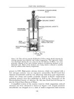
spur wheel and a single waterwheel. The water-driven corn mill at Barr Pool in
Warwickshire, shown in an illustration in the Universal Magazine published in
1729 (Figure 4.1), shows how the Vitruvian arrangement worked in the case of
the pair of millstones over the shaft. The same illustration shows a variant on the
Vitruvian mill in which a second pair of millstones was driven off a lay shaft,
and not by a great spur wheel. In the Barr Pool example it is clear that at the
beginning of the eighteenth century the millwrights were still working entirely in
wood, the only metal parts being the bearings and gudgeons.
In France, Germany and the Netherlands, the beginning of the eighteenth
century saw an upsurge in the study of millwrighting and mechanical
engineering. The professional millwright was becoming an engineer and he was
approaching millwork design scientifically rather than empirically. In France, in
1737, Bernard Forest de Belidor produced his classic volume Architecture
Hydraulique in which he showed designs for improved waterwheels. Buckets in
overshot waterwheels, though still made of wood with wooden soles to the back
of the bucket, were angled so that the water would flow in more smoothly, and
so that the water was held in the bucket for longer, therefore giving an increased
efficiency to the waterwheel. He worked out designs for all forms of floats and
PART TWO: POWER AND ENGINEERING
234
buckets for the waterwheels, and he improved the way in which the water was
led from the mill race through hatches, or launders, on to the waterwheels. It is
thought, too, that Belidor first formulated the idea that the wheel would be
better if the buckets were built between the rims so that the water did not spill
out at the side. He was working towards a greater efficiency in the use of water
power by also improving the design of dams and water controls.
One particularly important use of water power which grew in scale in the
seventeenth and eighteenth centuries was the supply of water for drinking
purposes in towns. In Paris, waterworks had been erected on the Pont Neuf
about 1600 and these were rebuilt by Belidor in 1714. In London, a similar
series of waterwheels was built under the northern arches of London Bridge by
Figure 4.1: The water-driven corn mill at Barr Pool in Warwickshire. This is the
illustration from the Universal Magazine of 1729.
WATER, WIND AND ANIMAL POWER
235
George Sorocold about 1700, to replace an earlier set inserted by Peter Morice,
a Dutch engineer, in 1582. Sorocold had been responsible for the installation of
several other water-driven water supply systems in English towns, including
Derby, Doncaster and Leeds. The system at Pont Neuf was known as a
‘moulin pendant’. The Seine rises and falls quite severely and so the
waterwheel has to rise and fall with it. Since the moulin pendant is a stream
wheel, which is turned only by the flow of the water, it is important that the
floats retain the same relationship to the flow of the water at all levels of the
river. At Pont Neuf the whole body of the pumps and waterwheel was raised
on four large screws as the water rose, so that the pumps could continue to
work. The waterwheels at London Bridge had a slightly different set of
conditions to deal with. The bridge spanned the tidal Thames and the starlings
(foundations) of the bridge piers reduced the water passage to 50 per cent of
the river’s width. At high water the difference in level across the width of the
bridge was 25cm (1ft) and at low water 1.38m (4ft 6in). To meet these
differences in level the shafts of the waterwheels moved up and down on
hinged levers and the gears continued to be engaged with the pumps since
they moved about the centre of the shaft on the hinged beams. Later
waterwheel-driven pumps were installed at Windsor (The King’s Engine),
Eton and Reading and these continued in use, in some cases, until the
beginning of the twentieth century.
In Germany there were similar pumps for pumping the town water at
Lüneburg, but more important examples existed to pump water for the
fountains in the Nymphenburg gardens, near Munich. The idea of the water
supply of formal gardens being raised from nearby rivers was developed to its
fullest extent in the Machine de Marly, built about 1680 to supply water to the
gardens and fountains of Versailles. Fourteen waterwheels were built below a
dam on the River Seine and the water was brought on to these wheels through
separate mill races. These undershot waterwheels were 11m (36ft) in diameter
and 1.4m (4ft 6in) wide. In addition to 64 pumps adjacent to the wheels,
connecting rods took a further drive a distance of 195m (600ft) to a second
group of 49 pumps which lifted the water a further 57m (175ft) above the first
reservoir. In all, the fourteen waterwheels operated 221 pumps and lifted the
water 163m (502ft) above the level of the river.
While the waterwheels of the period, such as those at Marly, appear to have
behaved well, they were clearly cumbersome and inefficient. The millwrights
were able to build large wheels with high falls, such as those in the
mountainous metal-mining areas, but these were still empirical in design. The
designs shown in the books of this period, such as Jacob Leupold’s Schauplatz
der MeuhlenBau-Kunst published in Leipzig in 1735, bridge the gap between the
apprentice system of training millwrights and the scholarly, scientific approach
which came later in the eighteenth century. Leupold’s book shows, by means
of copperplate engravings, exactly how water-driven mills could be built. The
PART TWO: POWER AND ENGINEERING
236
plans are very accurately set out, with useable scales, so that the millwright
could build his mill. The associated explanations, to be read with key letters on
the plans, explain every step which has to be taken. The illustrations show
grain mills, ‘panster’ mills with rising and falling wheels, mills with horizontal
waterwheels, boat mills, paper mills, oil mills, fulling mills and saw mills. They
are a design guide to every conceivable form of mill which the millwright
could be asked to construct. There are tables showing how the lantern gears
and pinions should be set out, so that the millwright could almost work with
the book propped up in front of him. There are other German text-books of a
similar character which produce even greater detail for the millwright. A good
example is the text-book on water-driven saw mills Von der Wasser-Muehlen und
von dem inwendigen Werke der Schneide-Muehlen by Andreas Kaovenhofer, which
was published in Riga in 1770. This book details all the joints and fastenings
required in a waterwheel, for example, and as in Leupold’s book details of
dam and watercourse construction are also included.
In France, the great encyclopaedia of Diderot, with its associated eleven
volumes of plates, was published between 1751 and 1772. These plates, like
Leupold’s, showed the methods of construction and manufacture of every
trade. Thus, in the chapter on the making of black powder or gunpowder, the
nineteen plates show not only the various machines required and the stages to
be undertaken, but also the way in which that machinery was driven. While
the purchase of a set of Diderot volumes would have been beyond the purse of
a master craftsman, enough copies would exist in manor houses and stately
homes for these plates to have been seen, and used, by the millwrights of the
locality. Indeed, it may well have been that the landowner as client would show
such books to his millwright. Modern understanding, based on mass
communication and transportation, finds it hard to realize how much
craftsmen moved about, and equally how the intelligent gentry absorbed
everything they could see and find on their travels abroad or on their ‘Grand
Tours’ with their tutors. If they had a mechanical bent they would follow this
up in the workshops and libraries of the countries they visited.
In the mid-eighteenth century there was an upsurge of understanding in
mathematics and science. In terms of millwork, one breakthrough concerning
the efficiency of the water-powered or wind-powered mill was the move, in
Britain, away from cog and rung gears to cycloidal gears (see Figure 4.2). This
was partly the result of the application of scientific and mathematical thought
by scientists like Leonhard Euler. In Britain, the application of science to the
profession of millwright was to be seen in the work of John Smeaton—a civil
engineer in the modern sense of the word. He was the designer of many types
of civil engineering works but he also designed forty-four watermills between
1753 and 1790, ranging from corn mills to iron-rolling and slitting mills. He
also carried out research into windmills and watermills which was published in
his paper ‘An Experimental Enquiry Concerning the Natural Powers of Water
WATER, WIND AND ANIMAL POWER
237
and Wind to turn Mills’ in 1759. His work was parallel to that of Christopher
Polhem in Sweden, and they could well have been aware of each other’s work.
Smeaton’s experiments set out to analyse the relationship between the various
waterwheel types, the head and flow of water, and the work these could do.
This had a great influence on the design of waterwheels for given situations of
fall, flow and power required. No longer was an empirical solution the only
one which answered a given problem, and design in the fullest sense of the
word came into the process of creating a water-powered answer to the
requirements of a factory.
Smeaton’s work was closely studied abroad, and the newly-created United
States of America in particular accorded new reverence to the scientific
solution of problems. The corn millers who had arrived in the eastern states
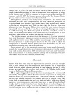
Figure 4.2: The low-breast shot waterwheel and gears at Hunworth in Norfolk.
This watermill still has all its wooden gears which date from about 1775.
Drawing by J.Kenneth Major.
PART TWO: POWER AND ENGINEERING
238
brought with them the old empirical solutions. Many of them had escaped
from the repressive laws controlling milling in Europe, and had brought their
old technology with them. However, they moved from small village mills, the
result of the ancient institution of milling soke, to create much larger mills.
Some of these were trading mills; others still worked on a toll-milling system,
but without the imposition of a landlord who had to have his ‘rake-off. These
millers frequently settled in an area where millwrights were not readily
available, and so books such as The Young Mill-Wright and Miller’s Guide by
Oliver Evans, first published in Philadelphia in 1795, were invaluable as guides
to the ‘do-it-yourself miller. He explains the science behind his designs, but
because of the problems in the emergent states, his machinery is still made of
wood. Evans, too, was the innovator of many changes in corn-milling practice.
The most important plant in the corn mills following the publication of his
book, was his grain elevator and horizontal feed screw, both of which cut
down on the amount of labour needed to run the mill. No longer were two
men required to hoist the grain sacks up the mill, nor to take the meal sacks
back up so that the meal could be dressed. As the meal fell from the millstones,
it was deposited at the foot of the bucket elevator to be taken up the mill to the
bins, from which it would pass through first one dressing machine and then
another, until it was properly graded. The screw crane for lifting and reversing
millstones when they had to be redressed is also an example of an arrangement
needing only the operation of one man. This was important designing in a
country which was short of labour.
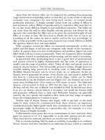
While Smeaton and Evans worked mainly with wooden machinery, by the
end of the eighteenth century cast iron had become cheap and was used for
millwork in Britain (see Figure 4.3). In Scotland, Andrew Gray published The
Experienced Millwright in 1803, and this was filled with many details of millwork
in which cast iron was the predominant material, particularly for gears, wheels
and shafts. At this time the machining of gears was not easy, so many
arrangements of gearing were built up using a large mortice wheel, in which
wooden teeth were mounted in sockets in an iron wheel, and a small all-iron
gear wheel. In the text-books of a parallel date in Germany, the millwork was
still made of wood. In fact, in Holland and North Germany iron millwork was
never used to any great extent before the water-driven mills ceased to work.
The use of cast iron enabled the mills to be better set out, as the iron gears
occupied less space. The change to cast iron also meant that the millwrights
either owned foundries, such as Bodley Brothers in Exeter, or had to send
designs or wooden patterns to the foundries.
Although the steam engine began to be used in factories in the 1750s, a large
growth in water-driven factories took place throughout the eighteenth century to
reach a climax in about the 1830s, at which time steam-powered factories
became universal (see Chapter 7). Water-driven factories for the production of
woollen cloth sprang up in the Yorkshire valleys and in the steep valleys of the
WATER, WIND AND ANIMAL POWER
239
west face of the Cotswolds, while cotton factories were built on the western flank
of the Pennine chain and in the Derwent valley in Derbyshire (see Chapter 17).
Here the power requirements were larger for each factory than for the humble
corn mill. Where the corn mill had managed with, perhaps, 9–11kW (12–15hp),
the cotton mill would need five times that amount. The Arkwright cotton mills
in Cromford, Derbyshire, and the Strutt cotton mill at Belper in the same county,
had huge waterwheels. That at Belper, designed and built by T.C.Hewes of
Manchester, was 5.5m (18ft) in diameter and 7m (23ft) wide. While the iron
wheels at Belper appear at first sight to be iron versions of wooden patterns,
there were many innovative features about them. In the first place, they were
suspension wheels, in which the rim was held equidistant from the hub by
tension rods rather than by stiff spokes. The buckets ceased to be angular but
had outer sides made of sheet iron in smooth parabolic curves which were joined
to the iron sole plates. The brick or stone casings to the wheel pit could fit more
perfectly because the iron wheel could be held in a circular shape more easily
than a wooden one, and in the head races new iron hatches gave a much more
sophisticated control of the water flow.
Figure 4.3: The conventional arrangement of a waterwheel and gears at Heron
Corn Mill, Beetham, Cumbria. This dates from the early 19th century and is a
combination of wood and iron gears with an iron waterwheel.
Drawing by J.Kenneth Major.
PART TWO: POWER AND ENGINEERING
240
During the eighteenth century water power also became more widespread
in the mining fields and in the iron- and metal-working areas. The preserved
site at Abbeydale, on the southern side of Sheffield, is an example of a
waterpowered edge-tool factory, and it was typical of dozens in the Sheffield
river valleys. A large mill pond was created across the valley, and on the
downstream side of the dam the various low buildings of the edge-tool factory
hide. There are four waterwheels: for furnace blowing, for tilt hammers, for
edge-tool grinding and to power the workshop. Apart from the forges with
their blowing engines, the edge-tool industry of Sheffield required grinding and
polishing workshops for the finish to be added to the tools. The preserved
Shepherd Wheel is an example of a grinding and polishing shop in which the
waterwheel drove twelve or more grindstones.
The nineteenth century
In the mining fields the introduction of cast-iron millwork enabled better use to
be made of the potential of water power. The use of waterwheels for mine
drainage and mine haulage had become well established in mining areas
throughout the world by the nineteenth century. In Britain there were some
very large waterwheels for mining purposes. The Laxey waterwheel on the Isle
of Man, built in 1854 by Robert Casement, is the largest surviving waterwheel.
This is a pitch-back waterwheel where the water is delivered on to the top of
the waterwheel in the opposite direction to its flow in the launder, and it is 22.1
m (72ft 6in) in diameter and 1.8m (6ft) wide. In the Coniston copper mines in
Cumbria there were several large haulage wheels. The biggest was 13.4m
(44ft) in diameter and 2.75m (9ft) wide, and there were others of 9.1m (30ft)
and 12.8m (42ft) in diameter. Down in the Paddy End copper ore dressing
works there were several waterwheels of which the biggest, 9.75m (32ft) in
diameter and 1.5m (5ft) wide, was replaced by a turbine in 1892. So much
water was used that the main streams were interlinked by four principal mill
races, and Levers Water was turned into a large holding reservoir by means of
a 9m (30ft) high dam. In a similar way the slate industry had water power for
its machinery, and at Llanberis in North Wales the factory and maintenance
works of the huge slate mines and quarries were powered by a waterwheel
which was 15.4m (50ft 5in) in diameter and 1.6m (5ft 3in) wide, built in 1870,
later to be replaced by a Pelton wheel (see p. 244).
On the continent of Europe and in the United States of America factories
began to spring up along the larger rivers. The New England states began the
concept of the factory town in which the factories were water powered. In
these towns complicated water power canals were arranged so that many
factories could be supplied in sequence as the water flowed through the town.
Lowell, Massachusetts, had an extensive power system of which the first part
WATER, WIND AND ANIMAL POWER
241
dates from 1820. Here the Pawtucket Falls on the Merrimack River were of
sufficient height to give an overall head across the town of 11m (35ft). An
existing barge canal was taken over, a new dam was constructed, and the canal
became the head race for the mills. Lateral canals supplied individual cotton
mills and the tail races were collected to form the head races of further mills.
At first waterwheels were used, but these were very soon replaced by turbines.
The Lowell system was followed in Lawrence, Massachusetts and Manchester,
New Hampshire. In parallel with the creation of Lowell’s water-power system,
one was brought into being at Greenock in Scotland where, in the early 1820s,
Robert Thom designed a system of dams and feeder canals. This system was
completed and at work in 1827 supplying 33 mills over a fall of 156m (512ft).
Similar schemes were put in hand on the river Kent, above Kendal in northern
England, for the corn mills, bobbin mills, woollen and powder mills of that
valley, and in the area around Allenheads in Northumberland, a further
scheme was created to serve the needs of lead mines and mineral dressing
works. John F. Bateman was the civil engineer responsible for the river Kent
scheme, and as an engineer he achieved a name for many water supply
schemes in Britain.
The need for water power went on increasing as the factory units grew in
size and a number of large millwrighting and engineering firms grew up in
Britain to meet the needs of the textile industries. Hewes has been mentioned
above for his work at Belper and, in combination as Hewes and Wren,
supplied the huge waterwheel for the Arkwright mill at Bakewell. Hewes had a
draughtsman named William Fairbairn in 1817, who left him in that year to
join in partnership with James Lillie. Lillie and Fairbairn were responsible for a
large number of big waterwheels in textile factories in Britain, and their
partnership was to run for fifteen years. One of their big wheels was at
Compstall, near Stockport in Cheshire. This breast-shot waterwheel, situated
between two halves of the mill, was 15.25m (506) in diameter and 5.2m (176:)
wide. Other wheel diameters available as stock patterns in the Fairbairn works
were 18.4m (60ft 4in), 14m (46ft), 12.1m (39ft 9in), 11m (36ft) and 9.15m
(30ft), and of course other sizes were also made. In using waterwheels of this
size a change had been made in the way in which the power was delivered to
the machinery. No longer was the shaft of the waterwheel extended into the
mill so that a pit wheel could provide the power take-off; instead, a rim gear,
often of the same diameter as the rim or shrouds, would engage with a pinion
on the shafts going into the mill. William Fairbairn was a famous civil engineer
and millwork formed only a small part of his business, but he did make several
changes in the design of waterwheels and the arrangements of the water
controls for those wheels. One innovation was the ventilated bucket on the
waterwheel. As the water went into an unventilated bucket, a cushion of air
was built up beyond the water which prevented the water from entering the
bucket smoothly. By providing a ventilation slot at the back of the bucket on