communications network test and measurement handbook
Bạn đang xem bản rút gọn của tài liệu. Xem và tải ngay bản đầy đủ của tài liệu tại đây (7.67 MB, 786 trang )
Part
Introduction to Network
Technologies and Performance
1
Source: Communications Network Test and Measurement Handbook
Downloaded from Digital Engineering Library @ McGraw-Hill (www.digitalengineeringlibrary.com)
Copyright © 2004 The McGraw-Hill Companies. All rights reserved.
Any use is subject to the Terms of Use as given at the website.
Introduction to Network Technologies and Performancel
Downloaded from Digital Engineering Library @ McGraw-Hill (www.digitalengineeringlibrary.com)
Copyright © 2004 The McGraw-Hill Companies. All rights reserved.
Any use is subject to the Terms of Use as given at the website.
3
Chapter
Open Systems
Interconnection (OSI) Model
Justin S. Morrill, Jr.
Hewlett-Packard Co., Colorado Springs, Colorado
A protocol is an agreed-upon set of rules and procedures that describe how multiple
entities interact. A simple example of a protocol in everyday life is the motoring rule
specifying that the vehicle to the right at an intersection has the right-of-way, other
things being equal. If this traffic protocol is violated, the result might be a serious
problem.
When the entities are network devices, protocols are necessary for interaction to
happen at all. If two devices follow different protocols, their communication will be
no more successful than a conversation between a person speaking French and a
person speaking Chinese. As there is more and more essential data traffic over a wide
variety of networks, the ability to guarantee protocol interoperability has become in-
creasingly vital. A number of standards have been developed to make that possible.
Among these standards, one has been designed to facilitate complete interoperabil-
ity across the entire range of network functions: the Open Systems Interconnection
(OSI) Reference Model, published by the International Standards Organization (ISO).
In computing and communications, open refers to a nonproprietary standard. An
open system is one in which systems from different manufacturers can interact
without changing their underlying hardware or software. The OSI model is such a
standard and is a useful framework for describing protocols. It is not a protocol itself,
but a model for understanding and defining the essential processes of a data com-
munications architecture.
Since its conception, the OSI model has become a vital tool in two ways:
1. As a point of reference for comparing different systems or understanding where
and how a protocol fits into a network.
2. As a model for developing network architectures that are maximally functional
and interoperable.
1
Source: Communications Network Test and Measurement Handbook
Downloaded from Digital Engineering Library @ McGraw-Hill (www.digitalengineeringlibrary.com)
Copyright © 2004 The McGraw-Hill Companies. All rights reserved.
Any use is subject to the Terms of Use as given at the website.
1.1 Data Communications Protocols
In data communications, all interaction between devices is specified by protocols.
These protocols are an agreement between sender and receiver defining conven-
tions such as:
■
When a device may transmit.
■
The order of an exchange.
■
What kind of information must be included at any given point in the transmission
(such as which sections of a data package contain addressing, error control, mes-
sage data, etc.,) or which wire is reserved for which type of information, as in the
interface described below.
■
The expected format of the data (such as what is meant by a given sequence of bits).
■
The structure of the signal (such as what pattern of voltages represents a bit).
■
The timing of the transmission (for example, the receiving device must know at
which points to sample the signal in order to correctly separate the bits).
The EIA 232 (also known as RS-232) physical connection, commonly found on the
back of data terminals and personal computers, is specified by a protocol. This pro-
tocol is defined by the Electrical Industries Association (EIA), a standards-setting
organization that assigns, numbers, and publishes the standards for manufacturers.
The protocol includes the pin assignments for each signal and the loading and volt-
age levels that are acceptable. When a data communications connection fails, this
protocol is usually the first to be analyzed for violations or problems that may impair
the link operation.
As data communications have evolved, many manufacturers have decided to com-
ply with standard protocols in order to ensure that their equipment will interoperate
with that of other vendors. On the other hand, there are still proprietary protocols
used that limit interoperability to devices from the same vendor. In either case, pro-
tocols provide the descriptions, specifications, and often the state tables that define
the procedural interactions that allow devices to communicate properly.
1.1.1 Layered protocols
Because of the complexity of the systems that they define, data communications
protocols are often broken down into layers, also called levels (so called because
they are schematically stacked on top of one another in order of use). The functions
at each layer are autonomous and encapsulated so that other layers do not have to
deal with extraneous details, but can concentrate on their own tasks. Encapsulation
also provides a degree of modularity so that protocols at the same layer can be in-
terchanged with minimum impact on the surrounding layers.
1.2 The OSI Reference Model
The OSI model, shown in Figure 1.1, consists of seven layers: Physical, Data Link,
Network, Transport, Session, Presentation, and Application. The upper layers are
4 Introduction to Network Technologies and Performance
Open Systems Interconnection (OSI) Modell
Downloaded from Digital Engineering Library @ McGraw-Hill (www.digitalengineeringlibrary.com)
Copyright © 2004 The McGraw-Hill Companies. All rights reserved.
Any use is subject to the Terms of Use as given at the website.
implemented in software, whereas the lower layers are implemented in a combina-
tion of software and hardware. Network test and measurement is concerned primar-
ily with the functions of the lower layers and not with the content of the message,
but with how well it is delivered.
Note: The layers of the OSI model may not be distinct in a specific protocol; in the
TCP/IP protocol suite, for example, the popular File Transfer Protocol (FTP) includes
functions at the Session, Presentation, and Application layers of the OSI model. Rather,
the OSI model represents a theoretical superset of what is generally found in practice.
1.2.1 The Physical layer (layer 1)
The Physical layer in a data communication protocol (also known as layer one or
level one) deals with the actual transmission of bits over a communication link. A
loose analogy for the physical layer is the function of the internal combustion engine
and the resulting source of mechanical motion in an automobile. The engine system
performs on its own as long as its lubrication, ignition, cooling, fuel, and oxygen sup-
ply elements are functioning properly, and as long as the operator avoids actions that
would damage the engine.
Protocols at layer one define the type of cable used to connect devices, the voltage
levels used to represent the bits, the timing of the bits, the specific pin assignments
for the connection, how the connection is established, whether the signal is electri-
cally balanced or is single-ended, and so on. The specifications of EIA 232 in North
America, or its V.24 European equivalent, are examples of Physical layer protocols.
Note: Numbering of protocols is done by the various standards bodies. The X and
V series are defined by the International Telecommunications Union (ITU) in Eu-
rope; the EIA standards are published by the Electrical Industry Association in the
United States. Other examples of Physical layer standards are the X.21 interface,
EIA 449 interface, V.35 modem, 10Base-T Ethernet LAN, and Fiber Distributed Data
Interface (FDDI) LAN.
The Physical layer elements interoperate with the media of connection and with
the next layer of abstraction in the protocol (layer 2, the Data Link layer). Its speci-
fications are electrical and mechanical in nature.
1.2.2 The Data Link layer (layer 2)
The Data Link layer provides error handling (usually in the form of error detection
and retransmission) and flow control from one network node to the next. It provides
Open Systems Interconnection (OSI) Model 5
Figure 1.1
Open Systems Interconnection (OSI) Modell
Downloaded from Digital Engineering Library @ McGraw-Hill (www.digitalengineeringlibrary.com)
Copyright © 2004 The McGraw-Hill Companies. All rights reserved.
Any use is subject to the Terms of Use as given at the website.
error-free transmission of a data parcel from one network link to the next. Using the
automobile analogy, the Data Link layer might be compared to sensing changing con-
ditions and modifying the inputs to the engine system to control it (for example,
slowing the engine by limiting fuel and ignition).
In most protocols, the Data Link layer (layer 2) is responsible for providing an er-
ror-free connection between network elements. This layer formats the data stream
into groups of bytes called frames of data for transmission and adds framing infor-
mation to be interpreted by the remote device to which the frames are sent. Data Link
layer functions generally exchange acknowledgment frames with the peer processes
(Data Link layer functions) of the device to which it is directly connected. This inter-
action confirms the receipt of data frames and requests retransmission if an error is
detected. Another major function of this layer is flow control, a provision for pacing
the rate of data transfer to prevent a fast sender from overrunning a slow receiver.
1.2.3 The Network layer (layer 3)
The Network layer provides error-free transmission of a single data parcel end-to-end
across multiple network links. Again with the automobile analogy, the Network layer
might be compared to the operator’s subliminal steering, which keeps the car on the
road, and negotiating turns at appropriate corners. Additionally, decisions to change
speed and make detours to avoid traffic congestion and even emergency avoidance of
accidents also equate to layer 3 functions. The driver controls these functions, but
does so automatically without thinking consciously about them, and can deal simul-
taneously with many other details that can be associated with higher-layer functions.
In data communication, the Network layer, layer 3, is responsible for the switching
and routing of information and for the establishment of logical associations between
local and remote devices, the aggregate of which is referred to as the subnet. In
some cases, this layer deals with communication over multiple paths to a specific
destination. The Network layer also can deal with congestion through flow control
and rerouting information around bottlenecked devices or links. Information perti-
nent to layer 3 is appended to the frame from the Data Link layer. Once this addition
is made, the result is a packet (named after a packet of mail that might be sent
through a postal service).
1.2.4 The Transport layer (layer 4)
The Transport layer is responsible for the end-to-end delivery of the entire message.
With the automobile analogy, this layer might be compared to the plan that the driver
executes in getting from the origin to the destination of the trip. Often this plan re-
quires using a map and choosing the most appropriate path based on the time of day,
the urgency of the arrival, and so forth.
Transport layer (layer 4) responsibilities include the integrity of the data, the se-
quencing of multiple packets, and the delivery of the entire message—not just to the
appropriate machine but to the specific application on that machine for which the
data is intended (i.e., port-to-port delivery). While the lower three layers tend to be
technology-dependent, the Transport layer tends to be independent of the end
users’ communications device technologies. This independence allows it to mediate
6 Introduction to Network Technologies and Performance
Open Systems Interconnection (OSI) Modell
Downloaded from Digital Engineering Library @ McGraw-Hill (www.digitalengineeringlibrary.com)
Copyright © 2004 The McGraw-Hill Companies. All rights reserved.
Any use is subject to the Terms of Use as given at the website.
between the upper and lower layers, and to shield the upper layer functions from
any involvement with the nuts and bolts of data transport.
1.2.5 The Session layer (layer 5)
The Session layer is responsible for establishing, maintaining, and terminating ses-
sions between users or applications (if they are peer-to-peer). This layer might be
very loosely compared to traffic laws that establish right-of-way.
The Session layer (layer 5) protocols establish conversations between different
machines and manage applications on them with services of synchronization and mu-
tual exclusion for processes that must run to completion without interruption. Pro-
tocols at this layer are responsible for establishing the credentials of users (checking
passwords, for example), and for ensuring a graceful close at the termination of the
session. An example of a graceful close mechanism is one that guarantees that the
user of an automatic teller machine actually receives the money withdrawn from his
or her account before the session terminates. Another example is the behavior of a
printer with a paper jam. The function that causes the printer to reprint the damaged
page, rather than going on from the jam point, is a Session layer protocol.
1.2.6 The Presentation layer (layer 6)
The Presentation layer ensures that the data is in a format acceptable to both com-
municating parties. It creates host-neutral data representations and manages en-
cryption and decryption processes. In the automobile analogy, functions at this layer
can be compared to a system that mediates geographically localized differences be-
tween automobiles, such as speedometer calibration in miles per hour or kilometers
per hour, or steering wheel placement on the right or left side.
The Presentation layer (layer 6) is concerned with the syntax and semantics of the
information that passes through it. At this layer, any changes in coding, formatting,
or data structures are accomplished. Layer 6 is typically the layer used to accomplish
encryption, if any, to prevent unauthorized access to the data being transmitted.
1.2.7 The Application layer (layer 7)
The Application layer provides the user or using process with access to the network.
In the automobile analogy, it is roughly comparable to the mission of the trip and to
the interface between car and driver (speedometer, odometer, gearshift, etc.). The
mission sets the context of operation, including the urgency and the conservative-
ness or aggressiveness of the trip.
This layer is concerned with network services for a specific application, such as
file transfer between different systems, electronic mail, and network printing.
1.2.8 User data encapsulation by layer
User data is formed and presented to the Application layer. From there it is passed
down through the successively lower layers of the model to the Physical layer, which
sends it across a link. At layers 7 through 2, information used by processes at each
Open Systems Interconnection (OSI) Model 7
Open Systems Interconnection (OSI) Modell
Downloaded from Digital Engineering Library @ McGraw-Hill (www.digitalengineeringlibrary.com)
Copyright © 2004 The McGraw-Hill Companies. All rights reserved.
Any use is subject to the Terms of Use as given at the website.
layer is appended to the original message in a process called encapsulation. This in-
formation is added as headers at layers 7 through 2, and as a trailer at layer 2 (see
Figure 1.2).
When the encapsulated transmission reaches its destination, it is passed up
through the layers in a reverse of the sending process. Each layer removes and
processes the overhead bits (header and/or trailer) intended for it before passing the
data parcel up to the next layer. This activity requires the precise exercise of a num-
ber of parameters and procedures, providing multiple opportunities for processing
error.
8 Introduction to Network Technologies and Performance
Figure 1.2 Encapsulation of data.
Open Systems Interconnection (OSI) Modell
Downloaded from Digital Engineering Library @ McGraw-Hill (www.digitalengineeringlibrary.com)
Copyright © 2004 The McGraw-Hill Companies. All rights reserved.
Any use is subject to the Terms of Use as given at the website.
9
Chapter
Data Communications Basics
Marc Schwager
Hewlett-Packard Australia Ltd., Victoria, Australia
2.1 Introduction
The purpose of this chapter is to provide a basic understanding of the major compo-
nents of a data communications network. This chapter focuses on the most common
elements likely to be encountered in a data communications network. Voice net-
works, wireless networks, and proprietary networks such as those used in process
control applications are not discussed. The treatment is necessarily brief; references
listed at the end of the chapter for further information.
2.1.1 The network fabric
The network fabric is the combination of devices, wires, computers, and software
that interact to form a data communications network. There are many of these that
are brought together to create the local area network (LAN) and wide area net-
work (WAN) environments that are in common use. There are three interlinked con-
cepts that this chapter addresses: the protocol stack (TCP/IP, SNA, etc.), network
topologies (ring, star, etc.), and the interconnects. The latter are the devices that do
most of the work in the network, such as routers, hubs, and switches. These three as-
pects of networking will determine a large part of how network testing is approached.
2.1.2 A brief history of data networks
Data networks evolved from three areas: mainframe communications, personal com-
puter (PC) networks that share peripherals, and workstation networks that share
data.
The early data networks were built around point-to-point networks, that is, one
mainframe was connected directly to another. IBM created protocols such as Remote
Job Entry (RJE) to facilitate load sharing and job sharing between computers. The
2
Source: Communications Network Test and Measurement Handbook
Downloaded from Digital Engineering Library @ McGraw-Hill (www.digitalengineeringlibrary.com)
Copyright © 2004 The McGraw-Hill Companies. All rights reserved.
Any use is subject to the Terms of Use as given at the website.
minicomputer companies in the late 1970s and early 1980s expanded these capabil-
ities considerably. With the widespread adoption of Ethernet and the proliferation of
PCs, small networks emerged that enabled a workgroup to share expensive periph-
erals like laser printers. Engineering workstations were being developed that had in-
tegral networking capabilities, which were used for data and task sharing. The end of
the 1980s saw the widespread adoption of networking and the creation of internet-
works. These large corporate, university, and government networks were essentially
a consolidation and interconnection of the “islands” of networking that had evolved.
These networks still carry many different protocols, and they connect many types
of computer equipment. The network fabric must be extremely flexible and adapt-
able to handle the task. This is one reason that there are so many different intercon-
nects. It makes the job of managing today’s networks challenging, and to make things
worse, traffic in a typical corporate network grew at around 40 percent per year in
the 1990s. The great intermeshing of networks will continue through the foreseeable
future, with the major focus on the consolidation of voice, data, and video over a
worldwide, high-speed fiber infrastructure.
2.2 Protocols
2.2.1 Common protocol stacks
Protocols are the language by which computers and other devices communicate on
the network. A standard model, which takes a layered approach, has evolved to de-
scribe these protocols. Defined by the International Standards Organization, (ISO) it
is called the Open Systems Interconnect (OSI) Reference Model. It has seven layers,
each of which has a function to perform. A collection of these layers is called a pro-
tocol stack. Interconnects will base routing decisions on the lower layers. Some com-
mon protocol stacks are profiled here, with comments on their use.
The OSI model. Table 2.1 shows the Open Systems Interconnect model. Note that
functions such as error detection can occur in more than one layer of the protocol
stack. While the OSI model covers seven layers in a complete implementation, there
are many protocol stacks that are focused at the Network layer and below. This is the
case in most of the following examples.
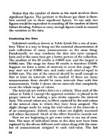
X.25. Table 2.2 shows X.25, which is common in wide area networks. X.25 is a trans-
port protocol stack, being defined only up through the Network layer. The use of hop-
to-hop error recovery at both the Data Link layer and the Network layer makes X.25
a very robust protocol stack, and therefore a good choice when line quality is poor.
Unfortunately this also makes it slow: X.25 can add 40 to 60 ms in traffic delay per net-
work hop. Frame relay is preferable for connecting LANs over a wide area network.
Frame relay. Like X.25, frame relay (described in Table 2.3) is a WAN transport pro-
tocol stack, being defined only up through the Network layer. The absence of hop-to-
hop error recovery makes frame relay much faster than X.25. Error recovery is
handled by the upper-layer protocols such as TCP/IP in a typical LAN environment.
Due to its low latency, frame relay is often used for connecting LANs over a wide area
network. Frame relay can deal gracefully with traffic bursts, and can specify quality
10 Introduction to Network Technologies and Performance
Data Communications Basics
Downloaded from Digital Engineering Library @ McGraw-Hill (www.digitalengineeringlibrary.com)
Copyright © 2004 The McGraw-Hill Companies. All rights reserved.
Any use is subject to the Terms of Use as given at the website.
of service (QoS). This is accomplished by having the user specify a committed infor-
mation rate (CIR), which the network agrees to deliver, and some burst parameters
that allow excess traffic in small amounts to pass through the network.
ISDN. Integrated Services Digital Network (ISDN), described in Table 2.4 has been
around for years. In the 1980s it was something of a holy grail in wide area networking.
It only broadly maps to the OSI model, so Table 1.4 should be treated as an approxi-
mation. It is designed to integrate voice and data traffic. Primary Rate ISDN (PRI)
has been well accepted as a WAN service in Europe. In the United States, Basic Rate
Data Communications Basics 11
TABLE 2.1 The Open Systems Interconnect (OSI) Model.
OSI layer Function
Application Provides common application service elements (CASEs) such as file transfer, virtual
terminals, message handling, job transfer, directory services.
Presentation Creates host neutral data representations, manages encryption and compression.
Session Manages setup and orderly teardown of conversations, synchronization to coordinate
data transfers.
Transport Connection management, fragmentation management, flow control, priority control,
error detection and correction, multiplexing data flows over one physical segment.
Network Controls the topology and access to the network. This layer links logical (or network)
addresses to physical addresses.
Data Link Detects and corrects errors in the received bit stream. Physical addresses are in this
domain.
Physical Transmits and receives the data. Specifications deal with the wire or fiber (known as
the media), connectors, as well as the optical or electrical signals that are carried on
the medium, including signal quality.
TABLE 2.2 The X.25 Protocol Stack.
Layer Service Notes
Network X.25PLP X.25 Packet Layer Protocol—Includes error recovery mechanisms
Data Link LAPB Link Access Procedure—Includes error recovery mechanisms
Physical X.21 X.21bis is the spec for V-series interfaces (typically RS232). X21 has it’s
own physical interface as well.
TABLE 2.3 The Frame Relay Protocol Stack.
Layer Service Notes
Network T1.606 This is the ANSI std, the CCITT equivalent is I.622
Data Link T1.618 Link Access Procedure—No error recovery mechanisms (LAPF)
Physical I.430/431 CCITT
Data Communications Basics
Downloaded from Digital Engineering Library @ McGraw-Hill (www.digitalengineeringlibrary.com)
Copyright © 2004 The McGraw-Hill Companies. All rights reserved.
Any use is subject to the Terms of Use as given at the website.
12 Introduction to Network Technologies and Performance
TABLE 2.4 The ISDN Protocol Stack.
Layer Service Notes
Network Q.931 Network Termination 2 (NT2), Error correction,
segmentation.
Data Link LAPD Q.921 Network Termination 2 (NT2) switching, layer 2 & 3
multiplexing, switching, concentration.
Physical BRI, I.4xx PRI, G.703 Network termination 1 (NT1). Line maintenance, timing, layer
1 multiplexing, physical, electrical termination.
TABLE 2.5 Transmission Control Protocol/Internet Protocol (TCP/IP).
Layer Service Notes
Transport TCP/UDP Transmission Control Protocol: connection-oriented, used by services
such as X Window, electronic mail, file transfer protocol (FTP), and
Telnet. User Datagram Protocol: connectionless, used by services such as
simple network management protocol (SNMP).
Network IP, ARP Internet protocol used for routing and addressing. Address Resolution
Protocol (ARP) maps physical addresses to IP addresses.
ICMP Internet Control Message Protocol (ICMP) supplies control and
error-handling functions.
Data Link LLC/MAC Link-Level Control/Media Access Control: This is typical for LANs.
802.3 Each LAN device has its own unique address known as the MAC address.
Other Data Link layer services such as Serial Line Internet Protocol
(SLIP), and Point to Point Protocol (PPP) are common.
Physical Various 802.3 is for Ethernet, Token-Ring is 802.5, others possible.
TABLE 2.6 The Novell Netware Protocol Stack.
Layer Service Notes
Transport NCP/SPX NetWare Core Protocol uses Service Advertisement Protocol to
link clients and servers. Sequenced Packet Exchange (SPX) used
for peer-to-peer networking.
Network IPX Internetwork Packet Exchange
Data Link LLC/MAC 802.2/3 Link Level Control/Media Access Control; this is typical for LANs.
Each LAN device has its own unique address, known as the MAC
address. Other Data Link layer services such as Serial Line
Internet Protocol (SLIP) are common.
Physical LAN 802.3 is for Ethernet, Token-Ring is 802.5, others possible.
Data Communications Basics
Downloaded from Digital Engineering Library @ McGraw-Hill (www.digitalengineeringlibrary.com)
Copyright © 2004 The McGraw-Hill Companies. All rights reserved.
Any use is subject to the Terms of Use as given at the website.
Data Communications Basics 13
TABLE 2.7 The SNA Protocol Stack.
Layer Service Notes
Application Function Mgt Data Provides application mapping such as application files.
Services (FMDS) Access to appropriate Network Addressable Units.
Presentation NAU Service Manager Network Addressable Unit (NUA) services manager.
Manager Supports data compression and session services.
Session Data Flow Control Manages connection flow (full, or half duplex, etc.)
Transport Transmission Control Manages end-to-end transmission for sessions.
Network Path Control Manages logical channel links, virtual route control.
Data Link SDLC Synchronous Data Link Control.
Physical Physical Physical connections.
ISDN (BRI) is finding broad acceptance for home office and Internet access applica-
tions. The next generation of ISDN, called Broadband-ISDN or B-ISDN, generally
refers to the Asynchronous Transfer Mode (ATM) protocol stack.
TCP/IP. TCP/IP (Table 2.5) is the protocol of the Internet. Above the transport,
many common services such as FTP, e-mail, Telnet, SMTP, and SNMP exist. TCP/IP
was developed by DARPA to be an extremely reliable transport (i.e., survive a nu-
clear war). It accomplishes this by allowing many different routes to a given end-
point, and by allowing for retransmissions if a packet fails to reach an endpoint.
Novell NetWare. NetWare is built around IPX, a Network layer protocol roughly anal-
ogous to IP (Table 2.6). Novell also supplies some higher-layer services (not shown)
relating to server-based file sharing and other workgroup functions. NetWare is one
of the most widely used LAN protocol stacks. The challenge with Novell has always
been how to scale it up across a WAN. This has to do with the way NetWare adver-
tises its services (frequently, and to almost everyone)—making for lots of WAN traf-
fic. Novell has added burst mode to improve performance, and also the option of
replacing IPX with IP in the stack to improve routing scalability.
The SNA model. IBM’s Systems Network Architecture (SNA), shown in Table 2.7, is
a hierarchical architecture. It is broken into domains, each controlled by a System
Services Control Point (SSCP), most likely a mainframe. The SSCP deals with Phys-
ical Units (PUs) and Logical Units (LUs), which are defined based on capability. Dif-
ferent LUs have different upper-layer network services available to them; for
example, LU1 is for application-to-terminal communications, while LU6 is for pro-
gram-to-program communications. PUs come in different types, including terminals
(PU1), hosts (PU5), and a variety of others.
2.2.2 Framing
Data generally moves in frames, packets, or cells. These packets are assigned ad-
dress fields, which are used by various devices on the network for routing, bridging,
and so on. Let’s examine how the packets are formed and addressed. As a piece of
Data Communications Basics
Downloaded from Digital Engineering Library @ McGraw-Hill (www.digitalengineeringlibrary.com)
Copyright © 2004 The McGraw-Hill Companies. All rights reserved.
Any use is subject to the Terms of Use as given at the website.
data moves from a computer into the top of the protocol stack, it gets wrapped in a
series of headers and trailers that allow each layer of the stack to do its job. A sim-
plified conceptual example of data moving from a computer through an IP stack onto
an Ethernet LAN is shown in Figure 2.1. This describes the basic elements, with
many detailed fields left out in order to reduce confusion.
Data starts on the local computer. As it is passed along, moving from the top of the
protocol stack down to the network interface card, it is broken into the correct size for
the protocol by the network driver. The network driver is a small piece of software that
communicates between the computer system and its network card. As the data pro-
gresses down the TCP/IP stack from the top, service information is added at the TCP
level. In the case of TCP, services are mapped to a logical entity called a port number.
Following this, the IP layer adds the Network layer addressing information (in this case
the IP address). The IP layer then hands the packet down to the Data Link layer, where
the media access control (MAC) address or physical address is appended. A cyclical
redundancy check (CRC) is added to the end of the packet to ensure packet integrity.
The packet is now fully assembled and ready to be passed to the Physical layer,
where it is turned into electrical or optical signals on the physical media. In some
cases the packet may be further processed by an interconnect. In the example, for
instance, the completed packet might move to a router to be transported across a
wide area network using the frame relay protocol. In this case, a frame relay header
and trailer would be appended by the sending router, and then stripped off at the re-
ceiving end by the receiving router. The process that happens at each layer of the
protocol stack, which treats anything passed down from above as data and appends
appropriate headers and/or trailers to it, is known as encapsulation.
2.2.3 Data forwarding functions
This section describes five key packet forwarding functions and their relationship to
the network stack. The network equipment that makes use of each function will be
discussed later.
14 Introduction to Network Technologies and Performance
Figure 2.1 Data framing.
Data Communications Basics
Downloaded from Digital Engineering Library @ McGraw-Hill (www.digitalengineeringlibrary.com)
Copyright © 2004 The McGraw-Hill Companies. All rights reserved.
Any use is subject to the Terms of Use as given at the website.
Repeating. Repeating occurs at the physical layer. Repeating is used to extend ca-
ble distances and to isolate noise. As shown in Figure 2.2, only the Physical layer of
the protocol stack is involved in repeating. A repeater simply looks at the electrical
(or optical) signals on the media, and recreates those signals on a second piece of
media. The new signals are regenerated and cleaned up to meet the physical speci-
fication of the Physical layer protocol. All traffic is repeated to all connections. No
destination decisions are made.
Bridging. Bridging is accomplished at the Data Link layer (Figure 2.3). It can be
used to connect two different physical media, such as the commonly used Ethernet
Data Communications Basics 15
Figure 2.2 The function of a repeater.
Figure 2.3 The function of a bridge.
Data Communications Basics
Downloaded from Digital Engineering Library @ McGraw-Hill (www.digitalengineeringlibrary.com)
Copyright © 2004 The McGraw-Hill Companies. All rights reserved.
Any use is subject to the Terms of Use as given at the website.
LAN cabling Thinnet (10Base2) and twisted-pair (10Base-T). Packets are forwarded
from one link to another as needed, based on the Data Link layer address. LAN
switching also works in this fashion, but at much higher speed. Network layer ad-
dressing is irrelevant for bridging.
Routing. Routing (Figure 2.4) operates at the Network layer; one use of routing is
to connect networks that have different Data Link layers. Common examples would
include connecting a LAN using Ethernet to a FDDI backbone, or connecting a LAN
to a WAN. Routing can be very complex, but with the complexity comes flexibility
and power. The most common Network layer protocol used for routing is IP, but Nov-
ell’s IPX and other protocols also are routed. Routing relies on careful configuration
in order to operate correctly. When configured correctly it provides secure, efficient
communications that can scale up to very large networks. For example, Hewlett-
Packard maintains a routed network with over 110,000 hosts worldwide.
Gateways. Gateways (Figure 2.5) are used when two entirely different network
stacks need to exchange data. Computers can be configured to act as gateways by
installing a card for each type of network, along with some appropriate software. To
connect a TCP/IP Ethernet network to an SNA network would require a gateway due
to differences at all levels in the protocol stack. Connecting an Ethernet network to
a Token-Ring LAN would require only a bridge, provided the upper layers of the pro-
tocol stack are the same.
ATM switching. Asynchronous Transfer Mode (ATM), shown in Figure 2.6, is a Data
Link protocol. It deserves special mention, however, both for its notoriety and for the
way it operates. Data is transmitted in small, fixed-size packets (53 bytes long)
called cells. The small cell size gives ATM the ability to interleave voice, data, and
video traffic and deliver deterministic performance. End stations have ATM ad-
16 Introduction to Network Technologies and Performance
Figure 2.4 The function of a router.
Data Communications Basics
Downloaded from Digital Engineering Library @ McGraw-Hill (www.digitalengineeringlibrary.com)
Copyright © 2004 The McGraw-Hill Companies. All rights reserved.
Any use is subject to the Terms of Use as given at the website.
dresses. ATM is connection-oriented, and a connection must be set up between the
stations prior to beginning communications. Connections are set up either manually
for permanent connections, or automatically for temporary connections.
ATM cells are forwarded by devices called ATM switches. To set up the connec-
tion, each switch in the path maps the input data stream to a specific output stream.
These are designated as unique virtual path identifier/virtual channel identifier
(VPI/VCI) pairs. Note that these change as they pass through each switch (Figure
2.7). When data is sent, the only address information in the cell is the VPI/VCI, which
may be different depending on where the cell is examined. While ATM can be used
directly by computers in an end-to-end fashion, it is more commonly used as a way
to carry IP or frame relay traffic in a transparent fashion.
Data Communications Basics 17
Figure 2.5 The function of a gateway.
Figure 2.6 The function of an ATM switch.
Data Communications Basics
Downloaded from Digital Engineering Library @ McGraw-Hill (www.digitalengineeringlibrary.com)
Copyright © 2004 The McGraw-Hill Companies. All rights reserved.
Any use is subject to the Terms of Use as given at the website.
2.3 Topologies
Networks are organized in different physical ways. These are called topologies.
Table 2.8 gives an overview of topologies. Included in the table are:
■
A diagram of the topology
■
Devices commonly found on this type of network
■
Protocols commonly used on the topology
■
General attributes of the topology
■
Notes on troubleshooting
■
General comments
2.3.1 Point-to-point
These were historically the first networks. Point-to-point networks are used for a
wide variety of situations, from connecting a PC to a server via a modem, to very
high-speed links connecting supercomputers. Failures are easily isolated to a single
link. Point-to-point networks do not scale gracefully. The number of links to connect
a given number of nodes is given by the equation
L = (2.1)
where
L = number of links
N = number of nodes
As N gets large, link creation and maintenance becomes difficult. For example, a
5-node network requires 10 links, while a 100-node network would require 4950
links!
N × (N – 1)
ᎏᎏ
2
18 Introduction to Network Technologies and Performance
ATM Switch
ATM Switch ATM Switch
VPI = 7
VCI = 24
VPI = 3
VCI = 7
VPI = 3
VCI = 7
VPI = 13
VCI = 2
VPI = 2
VCI = 8
VPI = 7
VCI = 24
ATM Address 2
ATM Address 1
Figure 2.7 ATM VPI/VCI pairs.
Data Communications Basics
Downloaded from Digital Engineering Library @ McGraw-Hill (www.digitalengineeringlibrary.com)
Copyright © 2004 The McGraw-Hill Companies. All rights reserved.
Any use is subject to the Terms of Use as given at the website.
19
TABLE 2.8 Network Topologies.
Topology Devices Protocols Attributes Troubleshooting Comments
Point-to-Point Mainframes X.25 Static addressing Failures easily First historic networks
Minicomputers Frame relay Fixed routes Isolated to a link
Modems ISDN Many links required to connect all nodes.
Interface cards SNA WAN links owned The formula is L = N*(N – 1)/2 for
SNA hardware SLIP and maintained complete coverage, where L is the number
Dial-up connections PPP by public carriers of links required and N is the number of
PADs Analog modem (many nodes to be connected.
PCs, terminals, speeds and styles
Workstations
Bus Mainframes (recently) Mostly Ethernet: 802.2, Thin or thick LAN coax Physical fault domain These were the first LAN networks
Minicomputers 802.3, LocalTalk for Ethernet: 802.3, 10Mbps spans entire cable
Print, file servers
PCs, workstations Rare but still existent UTP daisychained Physical faults are a Distance, number of host limitations
Transceivers –Arcnet, 802.4 for Apple LocalTalk major failure mode spawned interconnect market.
NICs Poor physical security
Repeaters Typically IPX, IP, Bus topologies are being rapidly replaced
Bridges AppleTalk, Banyan VINES by star topologies in private networks.
Routers
Ring Mainframes 802.5, FDDI Type 1, Type 3 Token-Ring Physical fault domain Driven by IBM, Token-Ring was one of the
Minicomputers connections limited by protocol in TR first; FDDI followed.
Print, file servers Token-Ring: Physical faults a Token-Ring, CDDI look like star topologies
PCs, workstations Typically SNA, 3270, IPX CDDI is Cat 5, major failure mode physically; FDDI on fiber looks more like a
NICs Multimode fiber for FDDI ring
Token-Ring only: FDDI:
–MAUs/MSAUs IP, DECnet,IPX 4 or 16 Mbps for TR, FDDI dual attach TR :
–CAUs 100 Mbps for FDDI mitigates failures; Source routing allows growth without
–Source route bridges Encapsulated TR on FDDI look for ring wraps routers, up to a point.
Bridges not uncommon 155 Mbps - 2.4 Gbps Distance, number of hosts, source
Concentrators (FDDI) for SONET/SDH Mixing TR and other hop limitations drive topology limits
Routers SONET/SDH in the protocols can be a
Multiplexers WAN/MAN problem source MANs use SONET/SDH rings
Star Mainframes 10Base-T, 100Base-X Typically Cat 3 or Component and wiring This is the most widely used LAN
Minicomputers 802.3 Ethernet Cat 5 wiring failures easily isolated technology today by a factor of 2.
Print, file servers ATM to a single link. It is quite inexpensive and typically
PCs, workstations 10Base-T for 10 Mbps easy to maintain. deployed in a hierarchical fashion
Transceivers Typically IP, IPX Violating distance or
NICs 100 Mbps LANs include configuration specs can
Hubs, stackable and 100Base-T, cause problems
modular (concentrators) 100VG-AnyLAN
Bridges, routers
Switches
Data Communications Basics
Downloaded from Digital Engineering Library @ McGraw-Hill (www.digitalengineeringlibrary.com)
Copyright © 2004 The McGraw-Hill Companies. All rights reserved.
Any use is subject to the Terms of Use as given at the website.
2.3.2 Bus
The use of a “bus” created the first LAN networks. Because any device on the net-
work can talk, a method was developed to minimize collisions on the network. The
scheme employed on Ethernet networks is Carrier Sense Multiple Access with Colli-
sion Detection (CSMA/CD). A station will listen to the network to see if any other
station is transmitting; if not, it will try to send its message. If by some chance two
stations do this simultaneously, a collision occurs. When one is detected, each sta-
tion waits a random interval and tries again. Collisions are a normal part of the Eth-
ernet world, tending to limit performance to around 60 percent of the theoretical
bandwidth, with throughput degrading under rising load.
Bus networks were easy to install in a small work area, and in small-scale usage
provided an easy way to add users. They were developed for office as well as indus-
trial use. Their use has been waning for a number of important reasons. One is com-
ponent cost. Bus networks tend to be based on coaxial cable, which is more
expensive than the twisted-pair wiring used in newer, hub-based networks such as
10Base-T Ethernet. A second reason is that the newer structured wiring designs
(star topologies) have isolated fault domains. When a bus network fails, it takes
down the entire segment, affecting all other users connected to the same physical
cable. Cable faults are a common failure with this style of network.
2.3.3 Ring
A ring network can appear physically like a star network. The ring configuration of-
ten only manifests itself in the path that data follows in the network. (See Token-
Ring MAUs below, for an example of this.) Ring LANs like Token-Ring and FDDI are
generally based on token passing, where each station can take its turn on the net-
work only when it has possession of a special packet called a token.
The advantage of this method is seen as the network utilization increases. Unlike
the CSMA/CD-based Ethernet networks, there are no collisions in a token scheme.
Token-passing networks therefore can maintain very high utilizations with little per-
formance degradation. The tradeoff is that the ring protocols have a higher over-
head, which cuts down the available bandwidth. Ring topologies such as Token-Ring,
FDDI, and SONET (used in the wide area) have built-in fault resiliency. FDDI net-
works have found wide application in campus backbones. The downside of ring net-
works has been the higher historic costs associated with them due to the extra
hardware required to implement the token protocols.
2.3.4 Star
While star networks have been used in the wide area for some time, it wasn’t until
the invention of the 10Base-T Ethernet hub that they became widespread in the lo-
cal area. The combination of low cost and structured wiring have made this topology
the most widely installed in LANs today. As in point-to-point networks, physical fail-
ures are easily isolated. These networks can be deployed hierarchically, avoiding the
scaling issues associated with point-to-point. Star networks can be interconnected
by a routing mesh, which looks similar to a point-to-point network. In a meshed net-
20 Introduction to Network Technologies and Performance
Data Communications Basics
Downloaded from Digital Engineering Library @ McGraw-Hill (www.digitalengineeringlibrary.com)
Copyright © 2004 The McGraw-Hill Companies. All rights reserved.
Any use is subject to the Terms of Use as given at the website.
work, each router is connected to at least two other points. This gives a measure of
fault tolerance in case one path fails, as well as the opportunity to balance the net-
work load.
2.3.5 Virtual networks
Virtual networks (Figure 2.8) have appeared relatively recently. The physical topol-
ogy of these networks is usually a hierarchical star or a routed mesh. Virtual net-
working allows you to gather arbitrary collections of nodes into a group for
administrative purposes even if they are on different physical subnetworks. For ex-
ample, you might put the members of an engineering team together in a group. The
advantage of this approach is administrative, and requires that the network inter-
connects have enough bandwidth to make any rerouting transparent.
2.4 Interconnects
Interconnects are the devices that comprise the network. There are many cate-
gories, and the distinction between them becomes blurred as networking companies
become more clever in their engineering and marketing. Some of the major inter-
connects are profiled in this section. The first section covers LAN devices and the
second section covers WAN devices.
Data Communications Basics 21
Figure 2.8 Virtual networks.
Data Communications Basics
Downloaded from Digital Engineering Library @ McGraw-Hill (www.digitalengineeringlibrary.com)
Copyright © 2004 The McGraw-Hill Companies. All rights reserved.
Any use is subject to the Terms of Use as given at the website.
2.4.1 LAN interconnects
This section contains descriptions of and comments about devices commonly found
on local area networks. Tables 2.9 and 2.10 contain the following information on LAN
interconnects:
■
Common name
■
Device function
■
Device limitations
■
Designing for reliability
■
Deployment hints
■
Troubleshooting issues
■
General comments
Transceivers. Transceivers (Figure 2.9) are used to connect the Attachment Unit
Interface (AUI) port of a computer or peripheral to the physical medium. Most of to-
day’s computers come with a 10Base-T port (RJ-45 connector) built in. A transceiver
might be used if you wanted to use a different medium, such as fiber. Transceivers
are inexpensive, making it worthwhile to keep spares on hand, as they occasionally
fail dramatically.
Repeaters. Repeaters (Figure 2.10) are used to extend cable length. They work by
replicating the signals at the physical level. A repeater can be used to switch media
types, in similar fashion as a bridge. Unlike a bridge, however, a repeater will not
limit Ethernet collision domains, that is, two workstations on different cables con-
nected by a repeater will still produce a collision if they transmit similtaneously. Re-
peater use is limited both by performance considerations (i.e., how many stations
are to be squeezed into a segment), as well as protocol dependencies such as inter-
frame gap preservation. A repeater will partition the network into two physical fault
domains, so cable tests must be done on each side if a physical fault is suspected. For
protocol problems, an analyzer can be hooked up anywhere. Repeaters generally will
not filter out protocol errors.
Hubs. Hubs (Figure 2.11) are the most widely used interconnect today. They are
used to connect end stations to a network. They may be connected in a hierarchical
fashion, up to a limit of three for Ethernet. Note that a different cable (or a switch on
the hub) is needed to connect two hubs together. If you need to configure the net-
work so that traffic passes through more than three hubs, a bridge, router, or a LAN
switch (discussed later) will be needed. The hub’s structured wiring approach limits
physical fault domains to a single wire.
There are two common hub packages: stackable hubs, and modular hubs or con-
centrators. The least expensive are stackables, which can be purchased by mail for
less than $100. The more expensive hubs come with built-in management capabilities.
Ethernet hubs act as multiport repeaters, so any traffic sent to one port is repeated to
22 Introduction to Network Technologies and Performance
Data Communications Basics
Downloaded from Digital Engineering Library @ McGraw-Hill (www.digitalengineeringlibrary.com)
Copyright © 2004 The McGraw-Hill Companies. All rights reserved.
Any use is subject to the Terms of Use as given at the website.
23
TABLE 2.9 LAN Interconnects (Part 1).
Name Function Limitations Design for reliability Troubleshooting Comments
Transceivers Used to connect Can be bulky, and can Transceivers can cause Failures easily isolated There are switch settings on
Also called computers and be knocked accidently network problems. to a link in 10Base-T. transceivers that can increase
Media peripherals to a local when handing off the Look for runts and With bus topologies, reliability or hinder performance.
Access area network. back of a computer. jabbers (short/long use an analyzer to Make sure these are set right for
Units of Occasionally fail packets with bad CRCs) localize. your network configuration. The
MAUs catastrophically. Keep failures to an address. “sqe” switch can clobber
a few extra repeaters.
transceivers on hand.
Repeaters Used to extend cable Typically operates at the There is a limit in Will propagate errors. If These were some of the first LAN
length or adapt physical layer. If it sees Ethernet of 3 repeaters Ethernet specs are devices. They generally have
different cable types. a signal, it will copy it. for a segment. violated, will cause little or no SNMP management
Copies all traffic from errors. If cables are capabilities.
one link to another. Exceeding this will cause suspect, cable tests
Multiport repeaters can problems with the should be run on each Hubs are also referred to
connect a number of interframe gap. individual wire. sometimes as repeaters.
coax links.
Hubs Hubs are used to Stackable hubs are Very reliable in general. Hubs have varying These are plug-and-play devices
connect end stations generally limited in Failures are easy to degrees of SNMP for the most part. When
to the network. They their flexibility. A series isolate in the star management connecting two hubs together in
may also connect other of hubs connected topology. Design the capabilities. This tends a 10Base-T environment, you
hubs in a hierarchical together will create network to conform to to vary with price. The must have a twisted cable. Most
configuration. These one large segment specification. Watch most expensive will of these hubs are built around a
are repeaters that (i.e., collision domain), cable lengths. No have embedded RMON single chip! The repeater MIB
operate in a star which can become point-to-point signal agents. You can see all will map MAC address to port
topology. They form congested. should pass through the traffic in a segment number. The more expensive
the basis of the more than 3 hubs by hooking an analyzer units will do some internal
majority of Ethernet before encountering a up to a port in the hub. bridging to create virtual LAN
networks today. router or a bridge. Collisions will vary by segments.
port. Do not be
concerned about this.
Token Ring The Media Access Unit Used in Token-Ring Token-Ring has a robust You can see all the traffic In a controlled environment,
MAUs looks like a hub, or star, environments. protocol which isolates in a segment by hooking Token-Ring is a stable protocol.
but operates in a Token The older connections fault domains quickly. an analyzer up to a port When connected to Ethernet via
Ring environment like are bulky and To take advantage of it, in the MAU. a router and routing common
a ring. It provides a way unwieldly. you should have a copy LAN protocols such as Novell or
for a computer to hook of IBM LAN Manager Depending on what you AppleTalk, problems are not
into a Token-Ring with or equivalent, and take are looking for, you may uncommon.
Data Communications Basics
Downloaded from Digital Engineering Library @ McGraw-Hill (www.digitalengineeringlibrary.com)
Copyright © 2004 The McGraw-Hill Companies. All rights reserved.
Any use is subject to the Terms of Use as given at the website.
24
TABLE 2.9 LAN Interconnects (Part 1) (Continued).
Name Function Limitations Design for reliability Troubleshooting Comments
what looks like a single the time to understand want to monitor
wire; it is actually two the protocol mechanism without inserting (in a
wires that form a piece and errors. There is a protocol sense) into the
of the ring. mechanism for ring. Make sure that
removing offensive your analyzer can
nodes from the ring. accomplish this.
Bridges Bridging operates at Passes all broadcast. Check your segment A bridged network can Bridges come with many different
layer 2 of the network. traffic. Can be limited traffic against the appear to an analyzer as forwarding and filtering
It connects one or more in forwarding and bridge forwarding rate. a single segment unless capabilities. For local area uses,
segments and passes filtering configurations. Spanning tree capability filtering is going on. LAN switches often provide a
traffic between them Some “bridges” are resolves potential This can make higher-performance solution,
based on the actually providing looping. Bridged troubleshooting although they provide no filtering.
destination MAC frame translation (such networks are very problematic when the It is hard to generalize, however;
address. These were as from Token-Ring to susceptible to broadcast analyzer is trying to if you have a multiprotocol
invented to overcome Ethernet). Others can storms. These are hard track 2500 hosts! To environment, consider taking the
distance limitations and do protocol level (such to pin down, and can troubleshoot broadcast step to routing.
traffic congestion as IPX) filtering. Bridge drastically reduce storms, you will need
introduced by repeaters. forwarding rates can network performance. the ability to capture
Also used to extend limit LAN performance If your network is packets in a protocol
LANs over the Wide it can vary by packet growing, consider analyzer. The general
Area size protocol mix, moving to routers The general technique
number of hosts, which, while harder is to capture
and protocol type. to configure provide continuously, and set
more flexibility, a trigger to freeze the
security, and buffer when a certain
manageability. level of broadcast
traffic occurs.
Data Communications Basics
Downloaded from Digital Engineering Library @ McGraw-Hill (www.digitalengineeringlibrary.com)
Copyright © 2004 The McGraw-Hill Companies. All rights reserved.
Any use is subject to the Terms of Use as given at the website.
25
TABLE 2.10 LAN Interconnects (Part 2).
Name Function Limitations Design for reliability Troubleshooting Comments
Source route Used to link Token-Ring Can handle a maximum Beware of overloading Watch the hop count This is a simple way to extend
bridges networks together. of seven hops. For intermediate rings limitation. Token-Ring without resorting to
larger networks, routers carrying transit traffic. routers.
are preferable.
Routers Link groups of Expertise needed for Make sure they are Monitor ICMP traffic for Routers allow network
computers and other correct configuration. configured properly. IP routing information. segmentation to reduce
network devices congestion.
together using Proprietary routing Stay current with Compression must be
network-level protocols can hinder firmware upgrades. turned off to use an
addressing. Includes interoperability. analyzer.
security and firewall
features.
Servers Servers are computers Packet forwarding speed, Configuration, especially If the server is also used These are general-purpose
that may be acting as and limited feature of security firewalls. for data storage, machines. They are not designed
gateways, proxy servers sets. monitor performance. to be high-performance
for security, or routers. Networking tasks can interconnects, and are thus
consume large amounts suitable for smaller networks.
of server resources. The exception to this is when a
server is configured to be a
proxy server for security reasons.
Lan switches These are fast Same as bridges. Subject Store-and-forward Unlike hubs, traffic is not These are plug-and-play devices
replacements for hubs. to broadcast storms. switches will check repeated on all ports. for the most part.
They forward traffic CRC and not forward
like bridges, working Limited to a maximum bad packets. Visibility is limited to
at the physical address of 3 layers one link at a time.
level. hierarchically, due to Cut-through switches Some vendors allow
address buffer do not do this, and are port mirroring to a test
requirements. faster. port.
ATM switches Very fast interconnects ATM standards are still Stay with a single Interoperability can be Connection-oriented networks are
that are used anywhere evolving. Single-vendor vendor until standards suspect across ATM fundementally different from
from the workgroup to solutions are more mature. devices. ATM is often LANs. ATM goes a step farther
the backbone, based on practical. used as a transport for and uses small cells to transfer
size and features. frame-based protocols. data.
These systems can be
complex. Testing
requires sophisticated
gear. Chances are good
Data Communications Basics
Downloaded from Digital Engineering Library @ McGraw-Hill (www.digitalengineeringlibrary.com)
Copyright © 2004 The McGraw-Hill Companies. All rights reserved.
Any use is subject to the Terms of Use as given at the website.