Scalable voip mobility intedration and deployment- P33 pot
Bạn đang xem bản rút gọn của tài liệu. Xem và tải ngay bản đầy đủ của tài liệu tại đây (147.19 KB, 10 trang )
320 Chapter 7
www.newnespress.com
off to the Wi-Fi network, without requiring the cellular coverage to be completely
diminished.
The second method is to attempt to avoid Wi-Fi handoff altogether, or at least to mitigate
the effects. The use of channel layering wireless architectures for Wi-Fi allows the Wi-Fi
network to perform the same task for its inter-access-point handoffs as the cellular network
provides for its inter-base-station handoffs. By centrally controlling and regularizing the
handoff process, the network frees the phone to having to make only a very simple choice.
Is the Wi-Fi network sufficiently strong to allow for a phone call, or is the cellular network
the correct network? This can eliminate the problem of poor FMC call quality for mobile
users in-building.
7.5 Cellular-Centric Technology with UMA
For voice mobility networks that may be considering a cellular-centric FMC solution, the
currently available technology is known as Unlicensed Mobile Access (UMA). UMA
integrates into the GSM cellular architecture, and uses the cellular-centric FMC architecture
to encode GSM signaling and bearer traffic directly over IP.
UMA requires the phone to have UMA-compatible software as well as the dual-mode radio.
The degree of integration of phone and handoff engines required for UMA is very high—
UMA interacts directly with the GSM engine—and thus UMA must be installed into the
cellphone by the manufacturer.
Within the carrier’s network, the FMC mobility gateway is installed as a UMA base station
controller. This controller uses what is known as the A interface to connect to the MSC, or
gateway switch. As far as the mobile network is concerned, the entire Internet-connected
phone population is local, not roaming, and connected to one special base station. The
UMA name for the FMC mobility gateway is the UMA Network Controller (UNC). As the
user hands out and in from the mobile operator’s network, the transitions which occur
appear to the GSM network as nothing more than an inter-BSC handoff. The one wrinkle to
this is that the mobile phone can be in a geographically distant area from the original
mobile network. In this case, because the IP traffic always goes back to the home MSC, the
handoff could very well be across MSCs and the PSTN.
UMA connects the phone the carrier directly using IPsec (Chapter 8). The phone uses a
preprogrammed DNS name for the UNC, after which it negotiates directly to the UNC
using ISAKMP, IPsec’s negotiation protocol used to set up the IPsec link. The IPsec link
uses encryption to ensure that the call can be neither eavesdropped on nor interfered with,
and protects the phone and carrier resources. UMA specifically uses a network address
translation (NAT)–friendly form of IPsec, which allows the UMA phone to connect from
Voice over Cellular and Licensed Spectrum 321
www.newnespress.com
behind the enterprise firewall. The outgoing message from the phone opens up the port in
the firewall, and the IPsec-encrypted payload is placed into a special UDP header for UDP
port 4500 (IPsec NAT traversal). The UNC accepts these packets and lets the encrypted
tunnel operate. The signaling traffic is exchanged as needed between the phone and the
UNC using this IPsec tunnel and GSM signaling within.
Once a call is placed, the bearer traffic starts. The bearer channel runs within the same
IPsec-encrypted connection, but has the DSCP for Expedited Forwarding (see Chapter 4 for
details on this). This ensures that the enterprise can apply quality-of-service handling to the
packets, in both directions, and enables the access point to send the traffic as a high-priority
packet—specifically for Wi-Fi, these packets will come out with the video, not the voice
prioritization, which means that you may wish to consider reclassifying the packet, as long
as WMM Power Save is not in operation. Bearer traffic is sent in 20ms intervals.
The only provisioning tasks required for enterprises are to ensure that the bearer channel
has priority and to provide enough capacity for the link to the carrier.
As of the time of writing, T-Mobile offers UMA for voice mobility networks, based on a
variety of handsets that encompass enterprise-grade features.
7.6 Potential Alternatives to FMC: Cellular-Only Technology
If the goal of FMC for a voice mobility network is to improve the in-building coverage,
rather than to provide true convergence of services, then there are alternatives which may
begin to gain in popularity. A number of U.S. mobile operators have begun to investigate
the idea of installing smaller base stations directly into buildings. The strategies divide into
two parts.
The more established strategy is for the mobile operator to work in cooperation with the
enterprise, to add what are called picocells into the building. A picocell is a small base
station meant to be installed within buildings to allow cellular coverage to be provided by
radios located within the building. The picocell devices are owned and managed by the
cellular carrier, who connects the devices back to their network using Ethernet cables or
similar. Picocells interact with the carrier’s network at the level of a base station or base
station controller. An alternative to this strategy is one in which the mobile operator takes
the burden of installing proper base stations outside the building, but uses sectorized
antennas and closer base stations to attempt to boost the signal inside the building. These
two approaches generally require the organization to have an outstanding contract with the
carrier for significant mobile services, or for the campus to be a place that tends to attract
public users.
For more private users, the carriers are now embarking on a strategy based around the idea
of femtocells. A femtocell is a device that looks much like a Wi-Fi access point, but is
322 Chapter 7
www.newnespress.com
owned by the carrier and operates in the licensed spectrum, connecting back to the mobile
operator over the public Internet. In terms of traffic flow, much like UMA (but not requiring
any changes to the handset), femtocells have the ability to place points of coverage
anywhere necessary. Currently, femtocells are being targeted for the home, for customers
who cannot get good access where they live or may be enticed by special discounts to
install one. However, femtocells may have an upcoming application for the deployment of
enterprise voice networks, and it would be wise to watch the developments to see where
they may lead.
323
CHAPTER 8
Securing Voice
8.0 Introduction
Security is the most important aspect for voice mobility networks. Of course, quality of
service must be there, or the network will not be used for long or with any sense of
appreciation. And the devices must be simple, and the network must be run well enough
that users do not notice when things are changed or the network is grown. However, no one
would use a phone if they thought that others were listening in on their calls. Enterprises
would abandon their networks left and right if strangers, criminals, or their competition
could listen in on the goings on in the network.
Voice mobility means no wires, and no wires means that there are signals. These signals do
not know the difference between a friendly receiver and an eavesdropper. As long as the
signal can make it to the attacker, the voice call is in jeopardy.
Furthermore, if the network is not protected from intrusion, it may serve as a free ride for
people looking to place anonymous, long-distance phone calls to wherever they may please.
The idea of an open connection to the voice network did not have to be confronted before
voice mobility, because the network ran on wires, and someone needed to gain physical
access into the building. The worst possible breach that was possible was trusted employees
making unauthorized calls from other workers’ desks. True, access to the actual
management consoles of the voice network needed to remain under lock and key, but
otherwise there wasn’t much that a malicious person could do with access to the phone
itself or the digital line it ran in on while inside the building.
But now, with voice mobility, new signals can come in, ones that are designed to access the
network from the safety of the parking lot. And if devices are stolen, there could be a free
ride into the enterprise from hundreds, or even thousands, of miles away.
The purpose of this chapter is not to scare anyone interested in voice mobility, but to bring
them comfort—comfort that security is an integral part of voice mobility technologies of all
forms. This chapter builds upon all of the different voice mobility technologies already
mentioned to show how the entire network can be secured.
©2010 Elsevier Inc. All rights reserved.
doi:10.1016/B978-1-85617-508-1.00001-3.
324 Chapter 8
www.newnespress.com
8.1 Principles of Security
A secure network provides the following:
• Confidentiality: No device other than the intended recipient can decrypt the message.
• Outsider rejection: No device other than a trusted sender can send a message correctly
encrypted.
• Authenticity and forgery protection: The recipient can prove who the original composer
of the message is.
• Integrity: The message cannot be modified by a third party without the message being
detected as having been tampered with.
• Replay protection: A older but valid message cannot be resent by an attacker later, thus
preventing attackers from replaying old transactions.
Each factor is a crucial part in protecting the network. Confidentiality, also known as
privacy, is the most obvious aspect of security. No one wants anyone unauthorized to hear
the message to be able to understand it. No one wants someone who is not a legitimate
party to a call to be able to listen in, take notes, and maybe record it for later.
Outsider rejection and authenticity are closely related, and are also necessary for secure
networks. Outsider rejection means, in this context, that no device that is not a part of the
secure network is able to send messages that can be used within the network. It is actually
possible for some networks to accept both encrypted and unencrypted data. It is also
possible for some encryption schemes, such as public key encryption, to allow any device to
send an encrypted message. For security, the network must stop both of these from
happening, for all real enterprise voice and data flows. Forgery protection and authenticity
is the concept that the encryption algorithms must be such that the sender’s authenticity is
known if the message correctly decrypts.
Integrity is the property that messages that are otherwise proper cannot be modified en
route to artificially inject data that was not there in the original message. Even if that
injected data were to normally appear as garbage that is carried deeper into the network an
attacker can use the weakness to affect the network. Networks, therefore, must not accept
any message that has been tampered with in any way.
Even when the message is authentic and free from tampering, and the contents are
unknown, an attacker can save up messages and replay them at later times. This replay
attack attempts to try to trigger behavior that was already requested, again, to take
advantage of whatever changes the request might make. Replay protection prevents this
from happening by not letting older messages be reused.
Securing Voice 325
www.newnespress.com
8.2 Authentication, Authorization, and Accounting
Services with RADIUS
Authentication and authorization are two different elements of networking. Authentication is
the process of using cryptographic procedures to find out what user is using a device and
verify that the user is actually who she says she is.
Authorization, on the other hand, is a matter of policy, and determines what a user can do
on the network. Authentication and authorization tend to be provided by similar
infrastructure, because authorization systems require that the users all be defined and
managed, and authentication uses the user database to prove out who each user is.
Accounting is a third aspect of network access. Accounting is a side activity to see what a
user has done with the resources she has available to her.
All three concepts are packaged together in the joint concept of Authentication,
Authorization, and Accounting (AAA). AAA is the heart of the security operations in any
network.
Simple user databases can be established independently in a number of devices. However,
the IETF created a network protocol and architecture definition, called Remote
Authentication Dial-In User Service (RADIUS), that has a separate server located within the
network dedicated to providing AAA services.
The term RADIUS belies its origins as the dial-up login mechanism for old modem banks.
When users dialed into a modem, the serving model would send text to the user, requesting
a username and password. This username and password would be matched in the user
database, and the user would be let on. Because modem banks were made of large number
of equipment, each piece of which needed to access the same user and password database,
the idea of placing the user database in one central machine was created. This became the
first incarnation of the RADIUS server.
The RADIUS server maintains the username and password database, or at least proxies it
from an alternative-technology central store (such as LDAP). Moreover, the RADIUS server
has the job of running the advanced, multiple-step cryptographic protocols that are used to
ensure tight authenticity of the user in question.
8.2.1 The Basic RADIUS Protocol
RADIUS runs on UDP, and is defined in RFC 2865. Port 1812 is set aside for RADIUS
access, with port 1813 used for sending accounting messages. The RADIUS server listens
on that IP address for a request for authentication, and then responds with a series of
challenges, or a final yes-or-no answer.
326 Chapter 8
www.newnespress.com
The device that does the requesting is never the user. Instead, users communicate through
some undefined means with a Network Access Server (NAS). The NAS itself must have a
shared secret in common with the RADIUS server, in order to use its services.
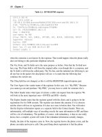
The NAS server gets the request for authentication from the user, and converts it into a
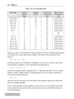
RADIUS message called an Access-Request. The format of the basic RADIUS message is
shown in Table 8.1. The code is the type of the message, as shown in Table 8.2. The Length
field is the length of the entire message. The Authenticator is used to verify the authenticity
not of the user, but of the NAS or RADIUS client, in a manner that preserves the user’s
password that the original RADIUS server used. Finally, the Attributes (see Table 8.3) carry
the important information about the user.
Table 8.1: RADIUS packet format
Code Identifier Length Authenticator Attributes
1 byte 1 byte 2 bytes 16 bytes
variable
Table 8.2: RADIUS codes
Code Meaning
1 Access-Request
2 Access-Accept
3 Access-Reject
4 Accounting-Request
5 Accounting-Response
11 Access-Challenge
Attributes are of the format type-length-value, as shown in Table 8.4.
Let’s look at an example authentication, using a simple password login pushed to the
RADIUS server.
The first message is an Access-Request from the NAS, as shown in Table 8.5. For an
Access-Request, the authenticator is a random nonce to be used just once and forgotten.
(The term “once” and “nonce” are, in fact, related, though it is not quite as clear as it might
seem.) Within the request comes the identifying information for the user. In this case, let us
assume that the client is logging in from login terminal, called “login-bank-01”, on that
terminal’s 23rd port. The username is “”. This is a strict username and
password login, so the user’s password, “password”, is padded out to be 16 bytes, then an
exclusive-or is applied with it to the MD5 of the shared secret and the nonce.
That is enough information for the server to determine whether the user should come in.
The RADIUS response is of the type Access-Accept, as in Table 8.6.
Securing Voice 327
www.newnespress.com
Table 8.3: Selected RADIUS attributes
Type Meaning
1 User-Name
2 User-Password
3 CHAP-Password
4 NAS-IP-Address
5 NAS-Port
6 Service-Type
7 Framed-Protocol
8 Framed-IP-Address
9 Framed-IP-Netmask
10 Framed-Routing
11 Filter-Id
12 Framed-MTU
13 Framed-Compression
14 Login-IP-Host
15 Login-Service
16 Login-TCP-Port
18 Reply-Message
19 Callback-Number
20 Callback-Id
22 Framed-Route
23 Framed-IPX-Network
24 State
25 Clear
26 Vendor-Specific
27 Session-Timeout
28 Idle-Timeout
29 Termination-Action
30 Called-Station-Id
31 Calling-Station-Id
32 NAS-Identifier
33 Proxy-State
60 CHAP-Challenge
61 NAS-Port-Type
62 Port-Limit
64 Tunnel-Type
65 Tunnel-Medium-Type
79 EAP-Message
80 Message-Authenticator
81 Tunnel-Private-Group-ID
328 Chapter 8
www.newnespress.com
Table 8.5: Access-Request for user/password login
Code Authenticator NAS-Identifier NAS-Port User-Name User-Password
Access-Request nonce
login-bank-01 23
encoded
Table 8.6: Access-Accept for user/password login
Code Authenticator
Access-Accept signature
Short and simple. The Authenticator field has an MD5 hash over all of the fields in the
response, as well as the shared secret. Of course, this authentication mechanism is not likely
to be appropriate for the voice mobility network. However, it gives a flavor for the
transaction.
The accept message from the RADIUS server can carry a significant amount of useful
information from the user database to the NAS. For example, the Filter-Id field can carry
the name of the filter policy to use for the client’s traffic. This is used on networks such as
802.1X (wired or wireless) to determine what firewall policy should be applied to the client
that is authenticating. The specific network the user is to connect to can be provided, as
well. The Tunnel-Type, Tunnel-Medium-Type, and Tunnel-Private-Group-Id can be used to
force a client onto a specific VLAN, for example. The meaning of the attributes and their
use depends on the NAS that is requesting the information.
8.2.2 EAP
The problem with the RADIUS protocol as previously described is that the authentication
mechanism is very limited. Authentication mechanisms need both to be cryptographically
strong—avoiding being intercepted or interfered with as they traverse the network—and to
support the authentication model that the network administrator wishes to use.
The cryptographic mechanisms used to provide the stronger authentication must be run from
the authenticating device to the RADIUS server. RADIUS was originally created with the
idea in mind that the authenticating device would pass the password to the NAS, which
would then authenticate the user on her behalf. But that cannot work for secure
authentication, in which the user’s device does not leak out the credentials. Instead, the
Table 8.4: RADIUS attribute format
Type Length Value
1 byte 1 byte
variable
Securing Voice 329
www.newnespress.com
user’s device and the RADIUS server need to have a back-and-forth, partially encrypted
exchange.
Furthermore, the authentication mechanisms that exist need to be extensible. Policies
change in organizations, and the administrator may want to change the authentication
method required. This must work transparently, so that the entire network does not need to
be retooled, just the RADIUS server and the client devices.
For these reasons, the Extensible Authentication Protocol (EAP) was created. EAP is
described in RFC 3748. EAP is a change in architecture for authentication. The goal of EAP
is not just to authenticate users and the network securely. It also must be able to
cryptographically derive keys that can be used for encryption sessions, for as long as the
authentication or login remains valid. Therefore, the EAP protocol, more than ever, needs to
not involve a third party.
EAP therefore makes the NAS into nothing more than a proxy, or a carrier. EAP itself is a
message-based request/response protocol and can be carried in different transports. EAP
over Ethernet or Wi-Fi is called EAPOL, for EAP over LAN. The same message can be
taken out of the Ethernet frame and placed into a RADIUS request or response, and is
simply called EAP over RADIUS.
EAP introduces, into the picture, the roles of supplicant and authenticator. The supplicant is
the software or module on the user’s device that performs the cryptographic authentication
protocols for EAP. The authenticator is an intervening device that puts the EAP messages
into the format the supplicant will receive. The authenticator could have been the last step,
but in real networks it proxies the EAP messages without processing them, to the RADIUS
server.
The result of a successful authentication will be a success or failure. On a success, both the
supplicant and RADIUS server will have negotiated a Master Session Key (MSK). The
MSK will be used as a root key to derive whatever session keys are necessary by the
protocol the client uses to access the network. In practice, the MSK is transported off of the
RADIUS server, which does not provide real network services, to whatever network
transport or application needs to decrypt the user’s messages.
The format of a generic EAP message is shown in Table 8.7. The Code field specifies the
type of the message, and is either 1 for Request, 2 for Response, 3 for Success, and 4 for
Table 8.7: EAP message format
Code Identifier Length Type Data
1 byte 1 byte 2 bytes 1 byte
variable