Scalable voip mobility intedration and deployment- P31 potx
Bạn đang xem bản rút gọn của tài liệu. Xem và tải ngay bản đầy đủ của tài liệu tại đây (264.38 KB, 10 trang )
300 Chapter 7
www.newnespress.com
throughputs of around 80kbps, by occupying portions of those channels. The downlink
channel does not require any contention, as it is point-to-multipoint, but the uplink channel
has to allow for initial uncoordinated access. Thus, a contention-based scheme is used.
GPRS provides for a radio with four different data rates, from 8 to 20kbps per slot. GPRS is
sometimes called 2.5G, because it is an addition to the 2G GSM.
To improve on the available throughput for data users, GSM has the Enhanced Data
Rates for GSM Evolution (EDGE) technology. This is a higher-throughput way of sending
traffic over the air for packet downloads. EDGE upgrades the radio to include more
sophisticated coding techniques. (For a more detailed introduction to coding techniques,
please refer back to Chapter 5’s description of Wi-Fi radios.) EDGE defines nine
data rates from 8.8 to 59.2kbps. Furthermore, EDGE offers better error correction coding
methods, to recover from noise or out-of-range conditions. It is impressive to see how
little bandwidth the licensed carriers have to work with, given that there is not a
wide range of available frequencies to begin width, and the signals travel so far that
spatial reuse becomes a challenge at every level. EDGE is sometimes referred to as a 2.75G
technology, because it improves upon GPRS but isn’t as modern as the newer 3G
technologies.
7.2.1.4 CDMA
CDMA—the name of the mobile technology, not the radio encoding—is defined in IS-95.
IS-95 does use the code division multiple access scheme to provide separation between
devices on the channel.
CDMA, as a radio technology, works by using the notion that streams of bit patterns can be
orthogonal to one another mathematically. For IS-95, each phone is given a unique
pseudorandom sequence, known as a PN sequence. The point of the sequence is that no two
sequences should correlate to each other, or agree in a statistical way, over any reasonable
period of time. The insight into CDMA is that the user can use these sequences by applying
an exclusive-or operation to the bit sequence with a bit sequence for the data it wishes to
send, a sequence created at a much slower data rate than the PN sequence. The PN
sequences’ randomness is preserved by the exclusive-or operation (compare to the
discussion on WEP security in Chapter 5). Once this is done, all of the phones transmit at
once, at the same time, into the same 1.25MHz channel.
This is quite a surprising use of the air. Instead of having each device coordinate or be
controlled, taking turns and not transmitting at the same time, to avoid collision, CDMA lets
them transmit at the same time, and uses the PN sequences to sort it out. How do the PN
sequences accomplish their goals? Because two different PN sequences are (pseudo)random
to each other, the two streams are not expected to correlate. In other words, the inner
product of the two streams should tend towards zero. Therefore, the receiver, knowing the
Voice over Cellular and Licensed Spectrum 301
www.newnespress.com
PN sequence of the transmitter that it wishes to listen in on, applies the PN sequence back
to the signal. The sequence of the sender falls away, leaving the original data stream, and
the sequences and bitstreams of the other devices becomes lower-intensity noise that must
be filtered out.
This mechanism, rather than slotting, is how phones are given access to one cell for IS-95.
One of the nice advantages of using CDMA is that IS-95 can perform another type of
handoff. Although the backend handoff sequence is similar to that of GSM, the over-the-air
part of the handoff can be made to disappear entirely. What happens is that a phone can
come in range of two base stations at the same time. When this occurs, the second base
station can be told of the PN sequence of the phone, and now both base stations together
can transmit the same PN sequence and data to the phone. In reverse, both base stations can
extract the phone’s traffic. This allows these two (or more) base stations to hold the signal
together, as the phone transitions from one physical area to another. This type of handoff is
called a soft handoff, because it does not involve breaking the connection in any way, but
rather in just transitioning state and resuming where the previous one left off. (Note that
CDMA is not the same concept as MIMO, which also works by having multiple devices
transmit simultaneously. MIMO uses the linear properties of systems with multiple
antennas, rather than the properties of statistically independent sequences carried on one
antenna.)
CDMA uses much of the same architectural thinking as GSM does. The major difference on
the backend side is that the protocols are not the same for the links within the private
mobile operator network. CDMA is popular among two carriers (Verizon and Sprint) in the
United States, and is not anywhere near as common as GSM is worldwide.
7.2.2 3G Technologies
With the demand for better throughputs for the data side of the picture, the cellular industry
is moving towards the next generation of technologies. These third-generation (3G)
technologies, are designed to offer throughputs that start to become reasonable when
compared to the consumer Internet service provider market, and therefore don’t seem as
antiquated to mobile users.
7.2.2.1 3GSM: UMTS and HSPA
GSM’s next phase was to undergo a radical change in radio type, to allow a different type
of network to be deployed. This generation of technology is named the Universal Mobile
Telecommunications System (UMTS).
UMTS uses a new type of radio, called Wideband-CDMA (W-CDMA). This is a CDMA
technology, and thus marks a shift away from the time-division scheme of second-
generation GSM technology. W-CDMA uses 5MHz channels—considered to be wideband
302 Chapter 7
www.newnespress.com
in the cellular world—rather than the far narrow channels in GSM. These channels are wide
enough for over 100 voice calls, or 2Mbps of throughput.
The networking technology behind the W-CDMA air interface is based on the GSM way of
thinking, however. SIM cards still exist, and have been expanded upon, to produce a
concept called Universal Subscriber Identity Module (USIM). The phones use the same
signaling protocols, and much of the backend infrastructure and concepts remain the same.
Because UMTS requires new spectrum, the United States allocated the 1700MHz and
2100MHz bands (getting close to the 2.4GHz of Wi-Fi, meaning that the signal starts
having difficulty penetrating into buildings).
UMTS is the networking technology of choice for converged, data-enabled handsets and
smartphones that are based on the GSM line of technology today. That does not mean that
UMTS networks are available in most places. Some urban centers have access to strong
UMTS coverage, but many other areas still remain with EDGE or even GPRS coverage only.
UMTS includes a way forward, for even higher throughput. This way forward is known as
High-Speed Packet Access (HSPA). The first and most promising step is to optimize the
downstream direction, as that’s where most of the Internet traffic flows to. This is called,
not surprisingly, High-Speed Downlink Packet Access (HSDPA). HDSPA allows downlink
speeds of over 1Mbps, and as high as 14.4Mbps. To get this, HDSPA uses a radio and
protocol that keeps tight tabs on the signal quality between every phone and the base
station. Each phone constantly, every two milliseconds, reports on how the channel is doing.
The base station then chooses who to send to, based on what will maximize the throughput
of the cell. HDSPA also uses some of the higher-end encoding technologies, up to 16-QAM,
to get better bits packed onto the air.
7.2.2.2 CDMA2000: EV-DO
The IS-95 architecture was not to left out of the improvements. CDMA2000 is the next step
up from CDMA, and provides higher throughputs.
The first step was for a 2.5G scheme, and is called by the unfortunately complicated name
of1xRTT. 1xRTT, for “One times Radio Transmission Technology,” uses the same channels
as the base IS-95, but adds an additional one times (“1x”) the number of orthogonal codes,
to allow more throughput to be packed onto the channel. (There is a limit to how often this
can be done, but CDMA had room to grow.)
That was a stopgap, however, so CDMA had to grow more. This is where the Evolution-
Data Optimized (EV-DO) technology steps in. EV-DO uses the same bands and channels as
CDMA, but completely changes the radio underneath. EV-DO provides downlink of
2.4Mbps to 3.1Mbps, depending on the version. EV-DO changes the radio by going back
the other way, to a time division scheme. EV-DO uses slots of fixed times, and for that slot,
Voice over Cellular and Licensed Spectrum 303
www.newnespress.com
the phone is the only device accessing the air. These slots are filled with up to 12 data rates,
using up to 16-QAM encodings to make better use of the air. Furthermore, EV-DO uses a
similar technique to HSDPA, in that the clients with the best signal quality will get the most
data, but in a way that preserves fairness across the phones.
EV-DO is being pursued by the U.S. CDMA vendors, the same way that UMTS is being
pursued by the U.S. GSM vendors. As the two paths borrow ideas from each other, they
seem to maintain their separateness, to allow the carriers to avoid having to completely
retool their networks or run parallel networks to support a common technology.
7.2.3 4G: WiMAX
WiMAX, one of two competing 4G technologies, is a different sort of thing entirely. It is a
mobile broadband technology. In some senses, WiMAX is quite a bit like Wi-Fi. WiMAX
belongs to the same family of wireless Ethernet, and is defined in IEEE 802.16e (as
opposed to 802.11). It is a packet-only network, designed to hook together mobile devices
into a base station and deal with the handoffs between them.
The major difference, and why I have categorized WiMAX as a cellular technology, is that
it runs in the licensed spectrum. WiMAX requires mobile operators.
7.2.3.1 Basics of WiMAX
WiMAX is derived around the concept of a connection. Its greatest strength is that it is a
tightly controlled point-to-multipoint protocol in which the base station runs the network
and the clients fit into it. Compare this to Wi-Fi, where the base station and access point are
nearly equal in role, when it comes to channel access. Furthermore, WiMAX allows for the
downstream and upstream to use different channels at the same time, whereas Wi-Fi is
based entirely on one channel of usage, the same for every direction.
WiMAX accesses the channel using a mixture of mostly contention-free slotting, but with a
small pool of contention slots for new stations to enter and reserve bandwidth. The slots are
not fixed duration, as they are in GSM TDMA. Instead, the slots’ lengths and timings are
determined by the base station, based on the resource requirements of each of the devices.
Clients must register with the base station, and then must request resources from there on out.
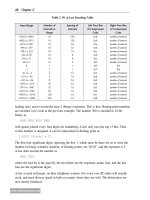
The WiMAX frame format is defined in Table 7.1, with the flags defined in Table 7.2. The
HT field is the type of the header, and is set to 0 for all but bandwidth requests. The EC is
the encryption bit, and is set to 1 if the payload is encrypted. Furthermore, the EKS will
be set to the encryption key sequence. The HCS is the header check sequence, and is a
checksum across the header. The LEN field is the length, in bytes, of the entire frame,
including the header and the CRC. The ESF bit signifies if there are extra headers in the
frame.
304 Chapter 7
www.newnespress.com
WiMAX can send a number of different types of frames, as determined by the Type field.
The Type field designates whether there is a mesh subheader, a retransmission request,
packing headers for submitting real data, or other operational controls. Some of the frames
are management, and some are data. The subsequent headers are used to define what type of
management or data frame is being used.
There are no addresses in the WiMAX header. WiMAX is connection-oriented. A client has
to request to come into the network. Once it associates to the base station, it is assigned a
connection ID (CID). This CID will be used to address the client, as needed.
WiMAX base stations transmit the WiMAX version of beacons. These frames, called
DL-MAPs, for downlink maps, specify the base station’s assumed ID, made of 24-bit
operator ID and a 24-bit base station ID. Once the station finds such a DL-MAP, it knows
that it has found service, and can look at the DL-MAPs and related messages to configure
its radio. After this point, it needs to associate to the network. It does so by waiting to learn,
on the downlink channel, the properties of the uplink channel that it will need to use to
connect. If it does not like the properties, it continues on to another base station. But if it
does like the properties, it will wait for the next uplink contention period, which is
advertised in the downlink channel, and then start transmitting on the uplink. These
exchanges are designed to let the station get tight radio timing with the base station,
ensuring that the contention-free part of the channel access works without interference—a
similar concern as with GSM.
Finally, the client can register with the network. The client’s registration message starts of
IP connectivity with the network.
The entire architecture of WiMAX is centered around the possibility that WiMAX stations
are managed entities, and the network needs to run like a cellular one, with strict
management controls onto the network and the devices in it.
Quality of service is strictly enforced by WiMAX. All quality-of-service streams are
mapped onto the connections, which then have resources granted or removed as necessary
to ensure proper operation.
Table 7.1: WiMAX frame format
Flags CID HCS Payload CRC
3 bytes 1 byte 2 bytes
optional
4 bytes
Table 7.2: The flags format
HT EC Type ESF CI EKS Reserved LEN
Bit: 0 1 2–7 8 9 10–11 12 13–23
Voice over Cellular and Licensed Spectrum 305
www.newnespress.com
7.2.3.2 Uses of WiMAX
WiMAX is not the sort of technology that most organizations will get to set up and use as a
part of a private voice mobility network. In fact, as of the time of writing, WiMAX is just
beginning to get rolled out to laptops, as an inbuilt option next to Wi-Fi for access.
The WiMAX model is to compete with 2G and 3G services for wireless broadband data
access. WiMAX can carry much higher throughputs, as high as 70Mbps divided up more
efficiently among the users, and so gives 3G a good run. Because of this, if WiMAX
manages to get rolled out in any significant scale, it could become an interesting component
in any enterprise mobility network, voice or data.
WiMAX’s biggest challenge is in market acceptance and coverage areas. One could argue
that WiMAX is just beginning to get started as a wide-area technology. And this statement
has a lot of truth. Unfortunately, if rollouts continue at the rate at which they have been,
and if the sour economic climate that exists at the time of writing continues into the coming
years, it is not clear whether organizations should expect to rely on WiMAX making
enough of a presence to be a factor.
For voice mobility specifically, WiMAX has another problem. It is a data network. Voice
mobility is not just about voice; it is about access to the entire services of the enterprise
when inside the building or out. But voice mobility makes sense mostly on converged
telephone devices, smartphones and business pocket devices that let people do work and
be reachable from anywhere. WiMAX is currently being looked at as a laptop option, to
provide better coverage within metropolitan areas and to possibly avoid having users feel
the need to scramble to find a Wi-Fi hotspot. Its greatest potential use is to fill the market
that emptied when metropolitan Wi-Fi failed to take off. Because of this goal, if WiMAX
achieves the ubiquity that cellular networks have and the quality and pricing models
that metropolitan Wi-Fi was to have, it could be an incredible tool for voice mobility
deployments in the upcoming years. But for now, we must sit on the sidelines and watch
the developments, and rely on 3G technology to provide the bridge for voice and data in
one convenient device.
7.2.4 4G: LTE
The other competing 4G network is known as Long Term Evolution (LTE). LTE is built on
top of the UMTS style of network but is also a mobile broadband network designed for
packet-based transmissions. LTE offers more than 100Mbps of throughput as a possibility,
which is a major breakthrough for a cellular technology because it equals the throughput of
wireline Fast Ethernet.
LTE is based on many of the same ideas as Wi-Fi but applied to a cellular network. This
means that using MIMO to achieve over 300 Mbps for four antennas, while applying the
306 Chapter 7
www.newnespress.com
necessary flexibility in how much spectrum a channel occupies, to be able to adapt to the
particular license that a mobile operator carries.
LTE further offers the option of using MIMO but distributing the antennas across multiple
users, producing something known as Space Division Multiple Access (SDMA). SDMA lets
the simultaneous nature of MIMO on the base station divide the same channel into multiple
transmissions to and from clients. Base stations using SDMA have a large number of
antennas but increase the efficiency of the channels used. Because carriers have very little
spectrum to work with, this also is a major benefit of LTE.
It remains to be seen whether LTE and WiMAX will start to compete for 4G networks in a
serious way or whether one will win out. As it stands now, WiMAX is heavily favored by
nontraditional carriers such as cable companies, with an investment mostly by one U.S.
carrier. GSM-based carriers are unlikely to adopt WiMAX and appear to be favoring LTE
at this point.
7.3 Fixed-Mobile Convergence
To this point, we have covered the two opposite ends of voice mobility: provide a private
network, using private branch exchanges, private wireline networks, and private wireless
coverage within a building; or use an existing mobile operator network, letting them take
care of the entire management of the technology itself, and therefore providing more time to
focus on managing the users themselves.
But each option, alone, has a number of downsides. Mobile-operator networks are
expensive, and if the mobile population spends time within the boundaries of the enterprise
campus, transitioning to mobility adds a cost that, whether per-minute or with bundled
packages, may not justify the transition away from stationary—but free to use—desk
phones. This is especially true if most of the calls are from user to user, and not to the
outside. Furthermore, the mobile operator’s network may not provide sufficient coverage
within the campus to allow this sort of mobility to work in the first place. Larger buildings
made of concrete and steel shield the cell tower’s signal from penetrating deep within the
building, and the cellular coverage may just not be sufficient for mission-critical
applications to run there.
On the other hand, Wi-Fi networks are local to the campus. It is difficult enough to extend
them to outside areas between buildings, but it is impossible to count on coverage once the
user leaves the domain of the administrator and walks out to the street. If the population is
mobile enough to need access inside or outside of the campus—whether they are road
warriors or occasional but critical resources who must be reachable wherever they go—then
Wi-Fi alone will not suffice.
Voice over Cellular and Licensed Spectrum 307
www.newnespress.com
For this reason, it makes sense to explore the convergence (an overused term) for
sure, of the two networks. Driving this is that many enterprise-grade (and high-end
consumer grade) mobile phones now have both cellular and Wi-Fi radios. Users are able to,
and are coming to expect that, the phone will provide the same features, at the same level of
utility, wherever the user is. For these users, the line between in-building and out-of-
building networks has become artificial, a detail that should be no more intrusive or
problematic than that of the user being able to access email from a desktop personal
computer or a laptop.
Thus, fixed-mobile convergence (FMC) can be approached from three different angles.
Those voice mobility planners who have traditionally provided their users with cellphones
can look towards the economic advantages of having a potentially large percentage of their
in-building phone calls be transferred off of the for-a-fee cellular network, into a free-to-
operate Wi-Fi network. Those planners who have thought of their workforce as only
needing in-building coverage, and had traditionally looked to phone technologies such as
Digital Enhanced Cordless Telecommunications (DECT) before Wi-Fi, may find that the
productivity increases brought on by allowing the phone to operate outside of the buildings
can justify pursuing FMC. Finally, planners who have strong in-building Wi-Fi and an
equally strong cellular solution may find that combining the two helps remove the
frustrations of users who cannot understand why there is a difference in their phone’s
capabilities when they are in the office than outside of it.
Fundamentally, FMC means settling on the use of a dual-mode phone, one that
supports both Wi-Fi and cellular, and providing both a strong Wi-Fi network and a well-
thought-out mobile workforce package, with remote email and mission-critical service
access. Therefore, both the carrier and the in-building network will be involved, as major
players.
There is quite a bit in common between the two approaches, especially at the level of
requirements that are placed on voice mobility administrators. They differ in the planning
and provisioning that is required, as well as in the choices available.
7.3.1 Enterprise-Centric FMC
However, FMC itself has two major approaches, different in how involved the carrier is in
the in-building network. The first approach, which we will call enterprise-centric FMC,
works by excluding the carrier in the understanding of the mobility. This model is very
similar to the way that mobile operators exclude the public telephone network from having
to know about the mobility in the first place. In an enterprise-centric FMC solution, the very
fact that the phone is mobile is only marginally included into the equation. The typical
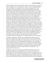
enterprise-centric FMC architecture is shown in Figure 7.4.
308 Chapter 7
www.newnespress.com
PBX
FMC Mobiity Appliance
Media Gateway
Public Switched Telephony Network (PSTN)
Telephone Lines
Telephone Lines
Telephone Lines
Dialing Plan
FMC Extensions
+ Cell Telephone
Numbers
Gateway
Switch
Base Station Access Point
Base Station
Controller
Phone
Dedicated Lines
Assigned Extension: 1111Assigned Number: (408) 987-6543
Owns Number:
(408) 987-6543
Owns Number:
(408) 555-1111
Carrier Network Enterprise Network
Extensions
Cellular Radio
FMC Dialing Software
Wi-Fi Radio
Figure 7.4: The Enterprise-Centric FMC Architecture
Voice over Cellular and Licensed Spectrum 309
www.newnespress.com
In this figure, the two separate networks are shown. The cellular network remains exactly as
it would normally be, unmodified in any way. The enterprise network is similar to how it
was before, except for the addition of an FMC mobility appliance, appropriately placed in
the center of the picture. In the enterprise-centric FMC architecture, the user’s telephone
number is owned by the enterprise. This enterprise extension becomes the number that
people use to reach the user, wherever she may be.
Everything centers around the FMC mobility appliance. This device integrates seamlessly
into the existing SIP-centric private enterprise network. Every enterprise FMC phone
requires an additional piece of FMC dialing software installed on the mobile phone. With
this software, the phone registers with the mobility appliance. The mobility appliance has
the database of every mobile extension that participates in the FMC operation, as well as
each phone’s cellular telephone number.
The main idea behind the enterprise-centric FMC architecture is that the mobility appliance
becomes the phone’s substitute when it is out of the office. The appliance accepts and
places all calls for the roaming user, as if he or she were present. To accomplish that, the
appliance bridges the calls back and forth to the mobile phone, over the cellular network.
When the telephone is in the Wi-Fi network (see Figure 7.5), the mobility appliance
maintains just a management role, for the most part. The mobile phone’s dialing software
becomes the focus. This software provides a complete SIP-centric soft telephone stack,
using the voice phone speakers and microphone, recording the audio and sending it over the
Wi-Fi data network. From the user’s point of view, the telephone appears to be operating as
a typical telephone, for the most part. From the enterprise voice mobility network’s point of
view, the mobile phone and dialing software appear as a standard SIP extension.
When the telephone leaves the Wi-Fi network, however, the mobility appliance springs into
action. The dialing software on the mobile phone registers back with the mobility appliance in
the enterprise. To do this, the cellphone may use its mobile data service to connect, over the
Internet, to the mobility appliance in the enterprise. The mobility appliance then turns on its
own SIP client engine. The engine assumes the identity of the user’s extension, and registers
on the user’s behalf with the PBX. The PBX is unaware that an FMC solution is in operation.
Instead, it is aware only that the user temporarily changed physical devices. As far as the PBX
is concerned, the user’s phone is located, physically, in the FMC mobility appliance.
When a call comes in for the user, the PBX simply routes the telephone call to the FMC
appliance, expecting it to answer. The mobility appliance gets the incoming call, and then
places a second, outgoing call to the mobile phone, as shown in Figure 7.6. Once the
mobile phone answers, the two calls will be bridged into one. At the same time as placing
the outbound call, the appliance sends a message over the cellular network to the FMC
dialing software, informing it that a call will be coming in and relaying the phone number
of the caller.