Scalable voip mobility intedration and deployment- P30 docx
Bạn đang xem bản rút gọn của tài liệu. Xem và tải ngay bản đầy đủ của tài liệu tại đây (512.32 KB, 10 trang )
290 Chapter 7
www.newnespress.com
Gateway
Switch
Base Station
Base Station
Controller
Phone
Public Switched Telephony Network (PSTN)
Telephone Lines
Dedicated Lines
Voice Codec
Extensions
Telephony
Application
Wireless Radio
Figure 7.1: The Anatomy of a Cellular Call
Voice over Cellular and Licensed Spectrum 291
www.newnespress.com
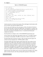
The base station is the antenna tower and network radio itself. These are located, with
overlapping coverage, everywhere the network needs to provide service. Usually, these
towers are on poles next to highways, on billboards, or on the sides or tops of buildings.
The mobile operator leases the sites that the towers are placed, and runs cables from the
tower to the shed, where the base station is located. The base station takes care of
generating the signals that run the cell, and making sure that each of the phones are
properly connected to the network, just as an access point does with Wi-Fi.
Located in a more central area is the base station controller. The base station controller
provides the intelligence behind the cell. A base station controller can have multiple base
stations attached to it, with dedicated digital links. The controller manages the base stations,
and controls the mobile phones associated to each base station. The radio behavior of
each of the base stations is determined and enforced by the controller, including channel
assignments coding operation. The compressed audio from the telephones also terminates
at the base station controller, which decompresses the audio, converting it into streams
of PCM.
The base station controller aggregates these audio lines, only some of which will have
phone calls active on them, onto trunks and sends the calls to the centralized gateway
switch. The gateway switch is the first true telephone switch, and straddles the border
between the public switched telephone network (PSTN) and the private network of the
mobile operator in the area. Gateway switches usually serve a geographic region, and serve
the purpose of bridging the call from the wireless portion of the network directly into the
standard telephone system. The gateway switch is the mobile operator’s “PBX,” not
surprisingly, and owns and manages the devices registered to it. The gateway switch
connects, through a trunk large enough to carry the voice load coming in from the network,
as the one point of contact to the PSTN.
Cellular uses the three-level architecture of gateway switch, base station controller, and
base station to separate out the functions related to telephones from those related to
operating a wireless service. The three-level architecture is, not by coincidence, very similar
to the one we have already seen for a Wi-Fi voice mobility network in the enterprise, with
an access point, wireless controller, and PBX mapping pretty closely. But the mobile
operator’s network is tightly integrated for the purpose of carrying voice calls. But in a
general sense, the gateway switch signals the calls “directly” to the mobile phone, with
the base station controller and base station proxying as needed to steer calls in the right
direction.
You may notice that the description in these sections is intentionally kept to a high level, to
apply to the different underlying cellular technologies and not draw too much from each
architecture’s specific terms and roles. In this way, the descriptions apply to all of the major
second-, third-, and fourth-generation cellular networks.
292 Chapter 7
www.newnespress.com
7.1.1 Mobility in Cellular
Probably the most interesting feature of the cellular architecture is the notion of portability
beyond the geographic region. It is fairly easy to see how mobility works within the
geographic region served by the gateway switch. A phone could simply show up on a
different base station another day, and the public telephone network would still interface
directly with the gateway controller and not be aware of the change. There is tremendous
value to this architecture, of course, in providing mobility within the geographic region, as
that is where most phones will spend their time. However, the question still remains of what
happens when the user takes his phone out of the geographic area and travels to another
one, with another gateway.
This intergateway scenario is known as a roaming scenario, because the phone is no longer
in the network operated by its gateway switch. Just as with PBX connections and enterprise
private telephone networks, the mobile network anchored by the gateway switch is assigned
the phone numbers for the phones that belong to that geographic region. When a phone
call is placed, from the public network to the mobile phone, the public network routes the
call to the gateway switch in the same way as when a phone call is placed to an enterprise
extension. Once the call arrives at the gateway switch, the public phone network no longer
needs to know where the call goes.
When the mobile phone is not in the network, however, the call must go somewhere. The
gateway switch usually provides, through another piece of equipment attached to it,
voicemail service. That works for when the mobile phone is off or its location is not known.
But the feature we are looking for here is roaming. To make roaming work, when the
mobile phone shows up in a geographic area not belonging to its mobile gateway, it needs
to have its location updated.
The roaming mobile phone first connects to the base station, and through to the base station
controller and gateway switch. The gateway switch knows the phone numbers that belong to
it, and therefore knows that this mobile phone does not belong locally. However, the phone
also reports information that lets the visited gateway switch determine where the home
gateway switch must be on the network. Then, the visited gateway sends a message over
the signaling system of the public network, SS7, to the home gateway, letting the home
know that the phone has relocated. The home gateway maintains a database, commonly
called a home location register (HLR), of all of the extensions that are owned by the home
gateway. This database includes all phones that are operated by that carrier in that
geographic region, wherever the phones actually are. In addition, the visiting gateway
maintains a separate database, called a visitor location register (VLR), which maintains the
list of phones currently associated to the gateway, regardless of whether they are managed
by that operator in that geographic region. The roaming phone registers with the gateway,
which updates the VLR with the phone’s information and the PSTN address of the home
Voice over Cellular and Licensed Spectrum 293
www.newnespress.com
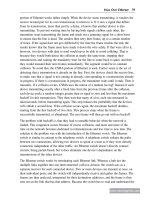
Home
Gateway
Switch
Landline
(650) 222-2222
Base Station
Base Station
Controller
Visiting
Phone
(408) 111-1111
Public Switched Telephony Network (PSTN)
1) Call for (408) 111-1111
2) Call is routed
by PSTN to
home ga
teway switch
3) Home gateway sees that (408) 111-1111 is
not in this network, but is visiting another
gateway. This switch looks up the location of
the other switch and creates a call to that one,
forwarding the call on.
4) Call for visitor gateway
originally for (408) 111-1111
5) PSTN routes call to visitor gateway,
not aware that this part is forwarded
5) Visitor gateway accepts the call,
pushing the audio down to the mobile
phone
Dedicated Lines
Home Location Register
Visitor
Gateway
Switch
Visitor Location Register
Figure 7.2: Cellular Roaming
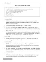
gateway. The gateway then sends the message to the home gateway, which marks the HLR
to indicate that the phone has roamed and records the PSTN address of the visited gateway.
Figure 7.2 shows the process for roaming. Now, when a call comes in for the mobile phone
at the home gateway, the gateway looks up its HLR and finds that the phone is located at
the visited gateway instead. The home gateway needs to forward the call over to the visited
gateway. To route the call, it places another call directly to the phone number of the visited
294 Chapter 7
www.newnespress.com
gateway, but when doing so, it attaches in the PSTN signaling a message saying which
phone the call is for. The visited gateway takes the call, looks up the VLR and finds that the
phone is local, and then directs the call through its network to the phone. It is as if the
phone had never left.
The reverse, a roaming phone calling a landline number, does not require forwarding
through the home gateway, because the public telephone network is capable of carrying the
outbound call with the caller’s phone number represented, even though the call itself is
coming from an area where that phone number cannot possibly be routed to. The public
network is trusting the operators to not put wrong information in the caller ID, and thus lets
equipment place whatever digits are desired to represent the caller.
One thing about roaming is that the dialing plan of the gateway the phone is currently
connected to may matter. This comes into play with international dialing and seven-digit (no
area code) dialing. If both gateways belong to the same mobile operator, there is a
reasonable chance that the visited gateway will use the dialing rules that belong to the
roaming phone. If the mobile phone in the figure dialed “333-3333” using this example, it
could connect with “(408) 333-3333”. But it is just as likely, and more so for international
roaming, that the visited gateway will enforce the local dialing plan. In this case, the phone
dialing “333-3333” may be forced to connect to “(XXX) 333-3333”, where “XXX” is the
area code that the visited gateway is in.
When phones are roaming between systems of different mobile operators, it is up to each
operator to decide whether the visiting phone should be accepted into the network, and
whether it will be able to place or receive calls. Roaming agreements between different
operators are written to keep track of when these phones roam and what they do on the
roamed networks, and the technology of both networks will monitor the operation and bill
the home network, and thus the user, accordingly. The fact that cellular roaming works over
international legs, where the visited gateway is an ocean away, is quite remarkable.
7.1.2 Mobile Call Setup
We have now looked at how roaming works. But within the domain of the gateway, the
phone must still register to the network, identify itself, and be able to both place and receive
calls.
At an abstract level, the concepts are not different from what we have seen earlier. The base
stations send out beacons, advertising their presence and what network they belong to.
The phone is built in with a preference for the network of the mobile operator who sold
the phone, and the phone will scan the various frequencies that may be employed for the
technology it uses, until it locates a beacon. At that point, the phone associates itself to
the base station and registers itself with the network directly to the gateway it is visiting.
Voice over Cellular and Licensed Spectrum 295
www.newnespress.com
The gateway authenticates the phone to make sure it is not a spoof and then updates its
VLR and the appropriate HLR, either its own or another.
When the phone wishes to place a call, it must gain access to the signaling channel. In
cellular technologies, as we will see for each of them, signaling and bearer are generally
kept separate, unlike with packet-based technologies. The signaling channel is packet-based,
however, and allows the phone to send out the call setup request. This signaling goes to the
switches, gets translated into a format the PSTN understands, and is routed to the final
destination. This continues for the remainder of the call setup. Once the call is established,
the signaling protocols ensure that there is a bearer channel—the specific form of which we
will leave for the specific discussion of architectures—and the call flows.
For incoming calls, things are slightly different. The phone does not have its radio
constantly powered on, waiting for an incoming call. Rather, the phone turns the radio off to
save power. When a call comes in, the gateway routes it through to the base station anyway,
which introduces a message into the paging channel. The paging channel is a broadcast
channel where all messages go for phones that may or may not be awake at the moment.
The paging channel repeatedly sends information informing the phone that it has an
incoming call. Once the phone wakes up for the moment and sees that there is a call
incoming, it comes out of power save and fully reconnects to the network. At this point, it
is now able to communicate back and forth, participating in the signaling activities. If the
call is accepted, the phone is granted a bearer channel, which it uses to encode the voice
upstream and decode the voice downstream.
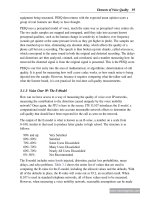
7.1.2.1 Handoff
Of course, mobile phones move. The caller typically has no idea where the coverage cell of
one base station’s radio ends and another one’s begins, and so calls need to be able to be
carried, seamlessly, across cell boundaries. The handoff mechanisms in cellular networks
are designed to do just that.
The three-level hierarchy (Figure 7.3) of the mobile network allows for a small variety of
handoff scenarios. When a phone is moving around the area of a base station, it may come
in and out of coverage of the multiple radios that the base station has. This is one type of
handoff that is very local. As the phone changes locations by significant amounts, however,
it might go out of strong coverage of one cell, and become parked between multiple other
cells, where it must then hand off across base stations. If the new base station is under the
same base station controller, than this can be a second type of handoff. If the phone crosses
to a new base station controller, however, the handoff occurs higher up the hierarchy.
As mentioned before, handoffs within one gateway switch can be handled without involving
the public network. The three types of handoffs beneath the gateway can usually take place
in the highest-level device in common on both paths. This is because the bearer channel
296 Chapter 7
www.newnespress.com
need only swivel, or pivot, from one line to another, and as long as the pivot device can get
the new leg allocated without breaking the old one—a make-before-break scenario—the
handoff can occur cleanly and without major changes.
When the handoff is between gateways, however, there is no central pivot point. One might
notice that the calling party always stays put, and so it could be conceivable that the calling
Base Station
Radios and
Sectors
a) Between Sectors b) Between Base
Stations
c) Between Base
Station Controllers
d) Between
Gateways
Base Station
Controller
Phone
Public Switched Telephony Network (PSTN)
Gateway
Switch
Figure 7.3: Handoffs at Every Level
Voice over Cellular and Licensed Spectrum 297
www.newnespress.com
party, or some public network switch, could just request a new line to the new gateway. But
the public network, by design, is not built for mobility and does not participate in the
handoff process at all. Therefore, the home gateway is required to follow the same steps as
in the previous section. It places a new call out to the new gateway, which then dedicates
lines down to the base station the phone is handing off to. Once everything is set up, the
phone drops its connection to the old base station, which frees up the lines up to the
gateway. The home gateway then immediately transfers the call from the old lines in its
domain to the call going across the PSTN, thus completing the circuit.
The major unknown factor in this process, for the mobile network’s point of view, is
whether the line connecting the two gateways will be available. Sometimes, it is not.
When that happens, the call will be dropped on the handoff, and the user will be forced to
redial. This transfer procedure is where the most can go wrong, but it is also supposedly a
less common event, considering that gateways are planned out to encompass areas of
population.
When a call that has already been anchored in the above way moves to yet another gateway,
the first visited gateway does not forward the call to the second. That would lead to a rather
pointless daisy-chaining of calls. Instead, the home gateway sets up the all directly over the
network to the new visited gateway and drops the call from the old visited one.
7.2 Cellular Technologies
Having covered the basic concepts of cellular networking, we can now look at the specific
forms that the technologies take on.
Cellular technology ranked in terms of generations. There are three well-defined
generations, and a nebulous, not well agreed-upon designation for the fourth generation.
The first generation of cellular technology was that of analog cellular phones. These phones
started people to be interested in the market for mobility, and provided the convenience of
wireless coverage, although with the possibility of getting static and noise in the call as the
caller left the range of the network. These have been surpassed by the next generation.
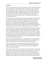
7.2.1 2G Technologies
The second generation, or 2G, of cellular technologies embarked upon use of digital phones
and signals to ensure that good quality was possible along a wider range of coverage.
Furthermore, the transition to digital allowed the introduction of security into the network,
with encryption to prevent eavesdropping.
There are two types of 2G technologies, and these two make up the basis for the cellular
networks worldwide today.
298 Chapter 7
www.newnespress.com
7.2.1.1 GSM
One digital 2G technology is known as the Global System for Mobile Communications
(GSM). GSM is the basis for most of the cellular systems worldwide, and introduced a new
concept into the world of cellular. Each GSM phone requires a SIM (Subscriber Identity
Module) card, which is provided by the mobile operator and includes the cryptographic
identity tied to the telephone number and user account. The SIM card also provides for
limited storage, intended originally to hold the address book that the caller can use for
dialing others. The advantage the SIM card holds for the user is clear: the user can
pull the card out of one phone, insert it into another GSM phone, and immediately, the
second phone picks up the phone number for the user and can be used to send and receive
calls. (The address book function is far less useful today, as address books are more
sophisticated now and the phone cannot convert all of the information to the SIM card
without loss.)
For the network, the advantage of the SIM card is that it stores the user’s identity. Each
SIM card is given a unique International Mobile Subscriber Identity (IMSI, pronounced
“im-zee”). This number represents the subscriber uniquely, in every country and in every
location. The IMSI is a 15-digit number. The first six digits name the mobile operator who
supplies the SIM and provides service. The first three of these digits specifies the Mobile
Country Code, and the second three specifies the Mobile Network Code. With these six
digits, a gateway that has a roaming phone connecting to it can find the home network. For
example, the first six digits of 310 170 would refer a phone to the former Pacific Bell
Wireless system in California, now the AT&T network.
GSM provides names for the three levels of architecture we looked at earlier. The gateway
switch is called the Mobile Switching Center (MSC). The base station controller keeps its
name, and is referred to as the BSC. The base station itself gets a new word, and becomes
the Base Transceiver Station (BTS).
The phones themselves are given a unique number as well, called an International Mobile
Equipment Identity (IMEI). This number identifies the phone to the network.
Between each of the devices in the network, GSM defines and labels each link. We will not
need to go into the names of these links here, but the concept is that each interface is
well-defined, so that mobile operators can (in theory) substitute one vendor’s equipment for
another. The most important interface for which this is true is the air interface (called Um,
for the detail-oriented). This is where multivendor interoperability comes into play.
MSCs communicate over the public signaling network using a protocol called Mobile
Application Part (MAP). This protocol takes advantage of the extensibility of the public
signaling network’s protocols to add, to the messages that travel from MSC to MSC, the
information necessary to run the mobile network.
Voice over Cellular and Licensed Spectrum 299
www.newnespress.com
7.2.1.2 GSM Radio
The GSM radio itself is based on the concept of time division multiple access (TDMA). The
idea is that the cell’s airtime is divided up into strict slots, or periods of dedicated access.
Devices using a bearer channel are assigned a particular, repeating sequence of slots, one
for each direction of the voice call. While the call is in progress, the phone is required to
send its traffic in one slot and receive in the other. The times in between allow the phone to
power down its radios in a predictable way to save power. The overall repeating pattern of
slots is called a frame. Each frame repeats nearly every five milliseconds, which means that
voice samples have to be packaged up into these short units.
The strict time sharing that GSM requires adds some complexity to the radios. The system
is not forgiving if a device gets the time slot wrong, because of the precise, periodic nature
of the system. Much of GSM’s complexity comes into play ensuring that every device is
synchronized so that they do not step on each other, even though the devices may at
different, long distances from the base station, and so the speed of light and propagation
delay impact the timing.
Each GSM channel provides only about 270kbps of total capacity, in which each frame asks
for the traffic from eight full-rate voice streams (and thus, phones in calls). Each full-rate
direction of a voice call encodes to 13kbps. This is the GSM codec that was referred to in
previous chapters, and is used by some IP-based telephone equipment as well.
GSM is defined in a few licensed bands. There are four bands available worldwide. The
United States and Canada use the 850MHz and the 1900MHz bands. The 850MHz band has
25MHz (barely wider than one Wi-Fi channel) for each direction: uplink is sent starting a
824MHz, and downlink is sent starting at 869MHz. These channels are spaced every
200kHz, and so there are 124 channel numbers, representing a pair of uplink and downlink
narrowband slices. Voice over cellular networks is incredibly efficient in terms of spectrum,
compared to voice over packet-based networks, although it must be pointed out that a link
to a phone provides enough bandwidth for only one voice call, and sending data packets on
that system is more complicated. The rest of the modern world uses the 900MHz and
1900MHz bands, which provide for more channels in total. Phones that are built to work
worldwide on GSM must be quad-band; that is, they must support both the North American
and international pair of bands.
7.2.1.3 GSM Data
GSM data services are provided by allowing the phone to allocate air resources that would
be used for other bearer channels, and instead is used to drive a different radio and protocol
for sending packet data.
The first method is called General Packet Radio Service (GPRS). GPRS uses an uplink and
a downlink GSM channel, but drives a packet radio over those bands. This provides