Scalable voip mobility intedration and deployment- P29 ppsx
Bạn đang xem bản rút gọn của tài liệu. Xem và tải ngay bản đầy đủ của tài liệu tại đây (231.6 KB, 10 trang )
280 Chapter 6
www.newnespress.com
• NeighborReports
• BeaconReports
• TransmitStreamMetrics
• QuietTime
• PowerConstraint(forsettingthetransmitpowerofclients)
Finally,theVoiceEnterprisetestcarriesoverthevoicequalitytestusedfortheten
immobile clients, and uses the same metrics to measure the quality of one call that is
forcibly handed off between two access points of the same vendor. The handoff need not
have the same voice quality during the handoff as before, but it must not exceed thresholds
of 100ms loss or delay, as of the time of writing. The test will be performed using
automated, sophisticated handoff and measurement systems designed to allow for
repeatability in measurement. Note that the test is not measuring the handoff performance
under density or variability, and so is intended to ensure the correctness of the
implementation of the underlying protocols, and not to measure whether any client handoff
decision-making scheme is better than another.
TheVoicePersonalprogramisnew,asofthiswriting,butahandfulofproductsare
availableforpurchasethathavebeencertied.TheVoiceEnterprisecerticationisstillin
progress—802.11k and 802.11r were not ratified amendments until fall 2008—but may be
readyby2010.VoiceEnterprisecerticationisexpectedtobeavailableasasoftware
upgrade for vendors that seek the certification.
6.4 Real Concepts from High-Density Networks
Chapter 5 introduced the basics of wireless coverage and Wi-Fi operation, and this chapter
has already covered some of the technologies that have been bolted onto Wi-Fi to improve
its usefulness for voice mobility. This next section will explore steps that voice mobility
planners can take to improve the quality of the network.
6.4.1 RF Modifications for Voice Mobility
One of the keys for voice mobility, especially when using a microcell-based architecture, is
to ensure that the RF plan and various parameters to the automatic planning tools are both
set to improve, not disrupt, the voice quality of the network.
The mobility of voice traffic requires two competing properties from the network: ensure
that voice traffic is interfered with or disrupted with as rarely as possible, and yet ensure
that coverage is high enough to increase the chances of successful handoffs. These two are
set against each other, because the techniques for mitigating the first increase the risks for
Voice Mobility over Wi-Fi 281
www.newnespress.com
the second, and vice versa. Therefore, the correct approach depends entirely on the density
of voice traffic, the ratio of voice traffic to data, and the likelihood of data congestion.
6.4.1.1 Less Voice than Data
Let’slookatwhattodowhendataistheprimarytrafconthenetwork.Whenvoiceisnot
expected to be used at a high density—for example, networks that do not include call
centers, auditoriums, or dense cubicle or desk farms—the biggest impact upon voice quality
is inconsistent and variable coverage. One reason this is true is that voice traffic is shorter
in bytes than data traffic, therefore exposing it to a lower likelihood of interference-related
packet error rates than longer packets, for the same bit error rate. Another is that the
background transmissions—even the co-channel transmissions that cannot be interpreted but
can be carrier-sensed—are overwhelmingly data transmissions, and not voice transmissions.
In this context, the voice traffic can be thought of, as a limiting approximation, as the only
traffic on the network, with just a higher noise floor from the background, irrelevent data
traffic. The topology and raw coverage of the network begin to matter more than the
capacity of the network.
When this holds, the two biggest concerns are to avoid network variation and ensure the
highestpossiblecoverage.Voicetrafc,notbeingbufferedandnotbeingsentreliablyatthe
transport layer as is data traffic, is remarkably good at exposing areas of weak coverage that
site surveys and data usage patterns have missed. Depending on the deployment and the
degree of weakness, large areas of the network can be found that perform tolerably on data,
but produce MOS values (see Chapter 3) that are not acceptable, let alone of toll quality. In
these areas, it is worth considering whether deploying an extra access point in that area will
raise the SNR enough to alleviate the problem. A good approach to test this out is to run a
long Ethernet cable to the location from a data jack and place the access point high enough
to peer over the tops of furniture or short walls. If the voice quality improves, then it is
worth considering a permanent installation.
Before installing that access point, check on the power levels of the neighboring access
points is recommended. Depending on whether the network is using RRM, or whether
installers or administrators have decided to turn down the power levels manually, the
problem may be fixed by simply reverting those changes and either setting a minimum (for
RRM) or static power level that is higher than the one currently in use. It may take some
trial and error to determine how many and which of the access points which cover the area
need to be powered up to improve the quality.
Network variance—especially power instability—is a major concern for voice mobility
deployments. The power instability arises from RRM or autotuning, which attempts to back
off the power levels from the maximum to avoid co-channel interference. The systems that do
this produce a power reduction on the basis of the signal strength detected from neighboring
282 Chapter 6
www.newnespress.com
access points, with those access points also adjusting their power levels dynamically. When
one access point detects enough neighbors with higher power levels, it will retract the size of
its cell by a predetermined threshold. This variation can happen as often as once a minute on
adaptive microcell systems. Because of this, adaptive power control can become a problem
for voice. One longstanding recommendation from at least one of the microcell vendors has
been to perform a site survey after an adaptive power control run has been performed, to
verify that the voice coverage is still sufficient. This is sound advice. In general, it is best, on
an ongoing basis, to either constrain or disable adaptive power control in these voice mobility
environments, erring on the side of higher power to prevent the power fluctuations from
causing momentary or long-lasting areas of weak coverage.
In terms of access point placement and channel usage, it is important to plan for the best
handoffs possible. Given the complexities of the scanning process mentioned in Section 6.2,
voice mobility installers would do well to plan specifically for voice, to help avoid some of
the problems that occur when coverage is tightened up. The two areas that the installer or
administrator can make the biggest impact is with increasing coverage overlap, and
carefully choosing the deployed channel set.
Handoffs tend to cause quality problems or lost calls when the phone is able to be rapidly
moved from an area of high quality to an area of low quality within timescales shorter than
it is tuned for. Furthermore, monopolistic coverage patterns—in which access points are
spaced, channels are chosen, and power levels are set—lead to higher risk when a phone
decides to attempt a transition, as fallback options are reduced or eliminated. Avoiding
monopolistic coverage can be performed by adjusting the ratio of the spacing of access
points to their power levels, by ensuring a higher-than-necessary minimum SNR when
performing a site survey or RF plan. Stated as one rule, the goal is to increase the signal
strength of the second strongest access point in any region where the strongest access
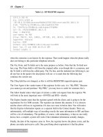
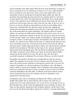
point’s signal is waning. Figure 6.10 shows the before and after.
The top part of the figure shows the goal of typical RF planning and RRM exercises. This
plan provides the most efficient coverage for the given SNR that is used to define the
boundary of the cells. Not a square foot is wasted, and the area of overlap between cells is
minimized. This efficiency is good for lean networking, but enforces the sort of
monopolistic coverage that is bad for voice. The graph on the right shows how the power
levels of one access point falls to the minimum acceptable SNR just as the other begins to
rise. This transition is as bare as can be, and at almost any location in the valley, the phone
has at least one of the choices being a poor one, resulting in bad signal quality and a broken
call. (In fact, with monopolistic coverage, the phone will have many choices, but all of them
but one are poor choices, for any given band.)
The bottom of the figure shows the results when the minimum SNR requirements for RF
planning are raised significantly above the actual minimum SNR requirements for voice.
Voice Mobility over Wi-Fi 283
www.newnespress.com
Access Point
Channel 11
Access Point
Channel 1
Access Point
Channel 6
Distance
Signal Quality
Access Point
Channel 11
Access Point
Channel 1
Access Point
Channel 6
Distance
Signal Quality
Figure 6.10: Reducing Monopolistic Coverage
284 Chapter 6
www.newnespress.com
Here, with the boundaries of the cell being the minimum voice SNR, the coverage overlap
has been increased substantially. In the overlap area, which has broadened, more than one
access point is capable of providing high-quality voice coverage. As the corresponding
graph on the right shows, as the phone moves into the overlap area, both of its choices are
good. Only when the coverage for the closest access point has improved to the point that
the phone would have nearly no incentive to search around does the other access point’s
coverage give way. This significantly reduces the risk of a poor handoff, and increases the
chances that the phone will scan to find coverage successfully.
Notice that taking this process to its limit results in channel layering, in which access points
on the same channel cover for each other by providing higher general signal strength, and
access points on different channels provide alternatives. Of course, channel layering does
not make use of client handoff procedures within a channel anyway, so this prescription
becomes less necessary and the number of access points can be reduced. Also notice that
increasing the second strongest access point’s signal in the transition zones increases the
interference, as well, and thus performing this technique can improve voice quality but
impact data. For this reason, some installers and network vendors may recommend to
deploy side-by-side access points, one for voice and one for data, or to dedicate one band to
voice and the other to data.
As a part of planning the network to improve the client’s handoff, reducing the channel set in
use provides the benefit of reducing the client’s search time. This is one of the reasons why
voice in the 2.4GHz band is more successful than in the 5GHz bands, even with dual-band
phones, as the 2.4GHz band has only three channels that must be scanned, practically.
Especially given that the majority of the channels in the 5GHz band are DFS channels, which
have complex scanning requirements that can make handoffs into those channels difficult to
perform, voice mobility deployments based on microcell architectures should consider
deploying voice in the 2.4GHz band or non-DFS U-NII 1 band in 5GHz, and setting data into
the DFS channels. Band steering techniques are useful, in this case, for forcing laptops and
other data devices into the 5GHz band if they support them. This sort of channel allocation,
however, is not particularly useful for channel layering.
6.4.1.2 Mostly Voice
In voice mobility networks that are mostly voice, or that have high densities of voice
clients, the previously mentioned techniques will not work. Most noticeably, the increased
density for voice both increases the risk of co-channel interference and increases the
problems of collisions for the high-priority traffic.
What to do in a dense voice situation depends on the capabilities of the infrastructure. For
microcell architectures, it is critical to design the network for capacity over coverage. This
means increasing the aggressiveness of the RRM engine, shrinking power levels in an
attempt to minimize the cellular overlap. Clearly, this will sacrifice handoffs and cause edge
Voice Mobility over Wi-Fi 285
www.newnespress.com
effects, but the tradeoff must be made, and in dense voice networks, the concern is to
produce a network that can support voice first. Handoffs and frequent mobility may have to
be traded for the ability to support infrequent mobility and flash crowds.
Increasing the power control aggressiveness has the effect of allowing the client’s transmit
power to become dominant. It is crucial to ensure that the microcell infrastructure that is
being tuned this way can set the power constraint for the clients. If this is possible, the
power constraint should be adjusted downward to match that of the network. Doing so will
prevent cell size mismatches and link imbalance, which increases the interference each
phone causes to its neighbors.
WMM parameters may have to be adjusted. There are two WMM parameters of
importance: the minimum contention window, and the maximum contention window.
Increasing the maximum contention window insures that highly dense networks can recover,
when collisions occur. Making this increase can push up latency and jitter a bit, but it does
so by reducing loss rates, which is the bigger problem to be solved. Especially when power
save is in use, it is critical that uplink packets be given every chance to arrive at their
destination, as these are the triggers for the downlink traffic. Adjusting the minimum
contention window may also need to be done. This is a trickier problem, as the minimum
contention window for voice must be altered in lockstep with the minimum window for
data, to prevent data from gaining a higher prioritization. The reason that the window must
be increased at all has to do with the probabilistic game of backoff that Wi-Fi uses to avoid
contention. Recall that in Chapter 5, we saw how each client picks a random nonnegative
integer less than the contention window. If the number of clients is high and the contention
window low, the clients have fewer numbers to choose from, and thus have a higher chance
of picking the same number and colliding. Increasing the minimum contention window
increasestherangeofpossibilitiesandchoicesforeachclient,restoringthebalance.Keep
in mind that the contention window is measured in powers of two, and thus an increase by
just 1 can make a difference. Unfortunately, it is difficult to apply any hard and fast rules to
this process. Therefore, worst-case planning is in order. For this reason, most vendors will
not recommend or necessarily support networks where the minimum contention windows
have been adjusted.
Additionally, when the density is high, the admission control parameters may turn out to be
wrong. Admission control matters the most when the network is crowded, and the more
crowded the access point’s neighbors are, the more resources may need to be set aside as
headroom on the access point to accommodate. WMM Admission Control access points
will often provide the ability for the administrator to cap the available voice capacity as a
percentage of airtime. Call admission control access points will provide the ability for the
administrator to cap the maximum number of calls. In either case, it may, ironically, be
necessary to reduce the maximum established call capacity for a given cell, as the number
of calls using the network rises.
286 Chapter 6
www.newnespress.com
VirtualizedwirelessarchitecturesavoidtheneedforsettingtheseWMMandadmission
control parameters, as the network determines the correct values as a part of ordinary
operation and can target individual values to individual phones simultaneously.
6.4.2 Site Survey
Site survey has a useful role in determining whether the network is adequate. When
planning for voice, or doing regular inspections, it is critical to ensure that the site survey is
done with voice in mind.
Most site surveys are performed by walking around with a laptop running site survey
software. This software is the inverse of RF planning. Rather than requiring the operator to
input the location of the walls and access points, and the tool spitting out the coverage
expected, the site survey tool requires the operator to stand at every point in the building
and input the location that she is standing in. The tool will then return the actual coverage
that is being produced. This is a laborious task, and may not be necessary for all areas of a
building, but will certainly be valuable for any areas where coverage has been historically
weak and has not yet been corrected for.
When performing a voice mobility site survey, the site survey tool should be set to subtract
a few dB from the signal that it provides. The reason for this is that phones tend to have
lower transmit powers than the network, because of both the smaller antenna design and the
need to reduce power for battery savings. Because of this, a site survey can give the false
impression that coverage is good because the laptop, with a good antenna, can hear the
downstream transmissions of the access point. A phone in that position may not get the
same coverage levels. Furthermore, the site survey tool does not measure the uplink. As the
phone may have a weaker uplink than the network, the result of this lack of measurement is
that the site survey may entirely miss areas where the access point cannot hear the phone.
For this reason, it is recommended to check with the vendor of the phones for any voice
mobility deployment on how the phone itself can be used for a site survey. Wi-Fi phones
have advanced modes that allow them to report back on the signal strength in each area.
Although not as fancy as using a site survey tool that has built-in mapping features, using
the phone itself allows the administrator to get a more accurate sense of the network, and to
immediately see where signal may be waning. When performing this sort of site survey, the
voice mobility administrator for a microcell infrastructure should check with the vendor of
the access points to see what they recommend that RRM should be set to during the site
survey. Because RRM changes the coverage, and thus invalidates the site survey, it may
become necessary to disable RRM completely and use a historical average for the network
settings. Again, refer to the microcell vendor to see if they support reverting to historical
RF settings. If not, it may be desirable to record the power levels that RRM sets manually
(by exporting the current configuration, for example) and to roll back by hand.
Voice Mobility over Wi-Fi 287
www.newnespress.com
6.4.3 Continuous Monitoring and Proactive Diagnostics
Running populated and well-used voice mobility networks can shift the focus to monitoring
for good voice quality. This is especially true for networks that have a history of
experiencing fluctuating voice quality, rather than having held steady for the network. In
these cases, diagnostics are in order.
There are two types of diagnostics which may be available, again depending on the
infrastructure technology chosen. Reactive diagnostics are concerned with measuring the
state of the network and reporting on the conditions as they change, or offering the
administrator a view into the state of the network using visualization, statistics, and
reporting tools. Proactive diagnostics, on the other hand, are concerned with active
measurement techniques to detect problems before they start.
The types of reactive diagnostics available to voice mobility networks are quite broad.
Many of these tools are basic to Wi-Fi networks in general, but some of the tools are
focused specifically on voice.
Many Wi-Fi networks that support voice allow the administrator to monitor the usage of
voiceonthenetwork.Lossanderrorrates,airtimeutilization,andlistsofthecurrently
active voice calls and registered phones all provide invaluable information about the state
of the network. It may take some time and experience to learn how these numbers and
statistics correlate with good voice quality. However, once learned, they can provide a
window into the operation of the network that helps establish what went on at the time in
question. As usual, it is not as important, for many of these values, what the absolute values
are at the time in question, but rather how they have changed when problems occurred.
Infrastructure-based client tracing and logging activity can be used to watch devices that are
currently experiencing trouble. This information can then be compared with the behavior of
a client that is not experiencing trouble to provide insight on what the problem might be.
Further analysis can be done with wireless network management reporting tools. These
tools can provide a summary of what each of the clients has been doing while on the
network, or can filter through information to provide useful aggregates. It is recommended
that any voice mobility administrator become intimately familiar with the network
monitoring tools and platforms that each vendor offers for its products.
When non-802.11 wireless noise becomes an issue, such as in areas with radio laboratories
or industrial microwave equipment, portable spectrum analyzers can come in handy. These
tools may not be as useful in Wi-Fi-only networks, but when non-802.11 noise is a concern,
these tools can be used to help classify the type of noise and allow the administrator to
track down the source or test better shielding methods for the equipment in general.
Passive protocol analyzers with voice capabilities, as mentioned in Chapter 3, can come in
handy for identifying problems in areas when these problems are occurring. These tools,
288 Chapter 6
www.newnespress.com
whether they are integrated into the infrastructure or placed separately in portable laptop
software, can deduce the quality of ongoing calls as they occur. Their greatest use is in
tracking down situations where some unknown factor is intermittently causing call quality
problems in an area. By placing these tools in that area and recording, the protocol analyzer
may be able to capture the problem as it is occurring, and using the voice quality metrics
may point the way for narrowing down the time windows that need to be searched for
without requiring the network administrator to stand at the spot with a phone in her hand,
waiting for the problem to occur.
Visualizationtechniquescanbepowerfulcomplementstodiagnosis.Two-dimensional
visualization can quickly reveal basic problems with wireless, such as excessive loss or
density.Three-dimensional“virtualreality”visualizationcanaddtheextraeffectsof
inter-floor issues and help lead to where coverage may be improperly applied. Site survey
tools can be used as a part of the visualization process when they offer remote modes that
allow a laptop to be placed in a location for remote monitoring.
Proactive diagnostics go a step further. Network-based proactive monitoring allows the
network itself to run trial phone calls and access services, recording success rates and
measuring quality automatically. The reports can then be analyzed for signs of upcoming or
newlyintroducedproblems.Voicemobilityadministratorswithhighlycriticalnetwork
locations may be able to use the PBXs proactive call quality measurement tools to test
phones, placed in strategic locations. These active call quality tools, associated with PBX
monitoring tools, place test calls and then report on the quality the endpoint perceived.
Although involved, this process can determine the behavior of the network and help head
off any problems.
6.4.4 When All Else Fails
When all else fails, and the voice mobility network is generally suffering, there are a few
options. The first option is probably the most painful, but can at least lead to stability. This
option is to turn on call admission control, if it is not already, and to set the capacity limits
to very low. This will result in busy tones for most calls that go through, but will help lead
to stability of the network itself, and thus provide a potential way forward.
Once the network is stabilized, the problem becomes one of adding capacity. If the network
is a mixed voice and data network, and the data traffic or the network settings necessary to
accommodate the network is causing the problem, then a parallel network may be in order.
If the network has room to grow (bands not filled, channel layers not deployed) and the
capacity is reaching its limit, adding additional access points to expand the raw capacity
onto those unused wireless resources can help. If all channels are used, and there is no more
room to grow, then segregating traffic can make sense. The use of traffic shaping for data
can provide enough headroom for voice to operate more reliably, especially for networks
that do not properly account for voice resources in their operations or radio tunings.
289
CHAPTER 7
Voice over Cellular and Licensed Spectrum
7.0 Introduction
Voice mobility is centered around the concept that the call should follow the user. What
happens when the Wi-Fi network runs to the end of its coverage, and yet people still want
to place a call? When the callers are out in the city, or driving to their next meeting, they
need to retain their access to the voice services. The only way to get the phone to work is if
it hooks up to a licensed mobile operator who provides coverage around the wider areas
beyond the building or the campus.
Cellular networking remains the predominant method that people get voice mobility today.
Adding in-building, privately managed wireless extensions such as Wi-Fi for voice to
operate on is still a new concept. In this chapter, we will see what makes cellular networks
work and then explore how to combine that technology with Wi-Fi to create a
comprehensive voice mobility network.
7.1 Anatomy of a Cellular Phone Call
Cellular networks the calls they provide address three basic and somewhat independent
concerns for voice mobility:
1. How the landline phone can lose its wires and be portable
2. How the phone number can remain the same, wherever the phone is actually located
3. How the call can remain connected, without disruption, as the phone moves from
area to area
Each of the three areas figure into the architecture of mobile telephone networks. Figure 7.1
shows the anatomy of a cellular phone call.
Most cellular networks share this architecture, though with different names and fancier
pieces hanging off the sides. From the bottom up, we can see the cellphone, which is an
advanced phone that uses digital technology to sample the audio, compress it, and send it
on its way. The radio features of the mobile phone ensure that the phone seeks out and
connects to the network.
©2010 Elsevier Inc. All rights reserved.
doi:10.1016/B978-1-85617-508-1.00001-3.