Scalable voip mobility intedration and deployment- P28 ppsx
Bạn đang xem bản rút gọn của tài liệu. Xem và tải ngay bản đầy đủ của tài liệu tại đây (217.36 KB, 10 trang )
270 Chapter 6
www.newnespress.com
scanning across channels, by reducing mandatory scan times for DFS, but also has an
enormous consequence for load on the network.
Most of these features may find usage as time progresses, or may wait for future standards
to refine them or produce a compelling application—there is some compelling location-
reporting capabilities in 802.11k that are itching for an application with the usage of
emergency call reporting. However, in the mean time, the complexity of the features means
that these technologies are less likely to be encountered in products implemented within the
next two years as of the time of writing.
6.2.6.8 What 802.11k Is Not
With all of the tools that 802.11k provides, there is a feeling among some people that it
must have enough to solve the major problems in wireless. Unfortunately, this view falls far
short of the actual state of affairs.
The main benefit of 802.11k for voice is that it can provide assistance for clients in their
scanning procedure. However, although there has been some speculation that the neighbor
reporting feature has the ability to direct clients to the most optimal access point, 802.11k
cannot actually do more than provide additional information to clients. The decision-making
ability is still firmly held by the client. The problem has to do with how neighbor reports
would be handled by clients. Neighbor reports, because of their size, are unlikely to contain
more than a couple of options for the client. However, there is nothing in the standard that
states how the access point should, or whether it ought to, cut down on the number of
neighbor report entries from the likely far higher number of neighbors expressed in the
Table 6.25: Transmit stream report
Measurement
Start Time
Measurement
Duration
Peer
Address
Traffic ID Reporting
Reason
Transmitted
Frame
Count
…
8 bytes 2 bytes 6 bytes 1 byte 1 byte 6 bytes
…
Discarded
Frame
Count
Failed
Frame
Count
Multiple
Retry
Count
CF Polls
Lost
Count
Average
Queue
Delay
Average
Transmit
Delay
…
4 bytes 4 bytes 4 bytes 4 bytes 4 bytes 4 bytes
…
Bin 0
Range
Bin 0 Bin 1 Bin 2 Bin 3 Bin 4 Bin 5
1 byte 4 bytes 4 bytes 4 bytes 4 bytes 4 bytes 4 bytes
Voice Mobility over Wi-Fi 271
www.newnespress.com
beacon reports. Notice how beacon reports can be gathered from stations anywhere in the
cell, and those stations on the edge of the cell can hear access points that are out of range of
the access point those clients are associated with. The net effect is that beacon reporting can
produce neighbor reports that cover a cell size over twice that of the access point. This is no
mistake, however. The optimal choice set of access points for clients, if optimal is restricted
to distance, is based entirely on where the client is, and not where the access point is. This
means that the access point is not necessarily in a good position to judge which neighbors a
client can see or would want to use. The best way for the access point to determine what
the client sees is to ask it with a beacon request. However, any information the client has
would already be used by the client in its handoff decision making, and the access point
cannot add anything.
Lookingatthesameproblemanotherway,aclientjustenteringacellandaskingfor
neighbors has an excellent chance of being told about neighbors that are out of range of it,
because they lie on the far side of the cell from the client. The answering access point can
try to pick an optimum for the client, but that would require the network tightly tracking the
location of the client in real time. Doing so is not a bad idea, but it may require a different
architecture than is typical for microcell environments.
More to the point, even if the neighbor reports were optimal, the client has no way of
knowing what type of network it is connected to, or whether the network is providing
optimal results, useful results, or just anything it feels like. So the designers of clients have
a strong incentive to not treat the neighbor report as definitive, and to just add the
information provided into the mix of information the client already has. In fact, if the client
vendor thinks that it has done a good job in producing the scanning table, then following
the lines of the discussion in Section 6.2.2.4 on the handoff decision-making process, then it
would be wise to not depend on neighbor reports in any way.
This tension makes it difficult to know whether the 802.11k mechanisms will finally
eliminate most voice handoff issues, or whether they are adding a degree of complexity
without the same degree of value. It this sense, it is unfortunate that clients are left in
control of the process, with no specification as to why they should hand off. Cellular
technologies have been successful in producing this sort of assisted handoff (though
reversed, with the network making the decisions and the clients providing the candidates it
might like), mostly because the end-to-end picture is adequately known. Wi-Fi will need to
overcome its challenges for a similar scheme to be as effective.
Nevertheless, the presence of network assistance greatly improves the operation of networks
compared to those with neither assistance nor control, and is necessary for high-quality
voice operation for microcell deployments. Section 6.4 will explore better ways to tune the
network for voice deployments.
272 Chapter 6
www.newnespress.com
6.2.7 Network Control with Channel Layering and Virtualization
As mentioned earlier, there are two broad options for improving upon the original Wi-Fi
mechanism for independent, client-driven handoffs. Network assistance seeks to improve
the accuracy and adequacy of the client-driven decision process, by offering the client more
information than it would have on its own, in hopes that pathological decisions can be
excluded, and better decisions can be made. The protocols can be quite sophisticated, and
the client is required to become significantly more intelligent in order to take advantage of
them. The other option is to remove the client’s ability to make poor decisions, by limiting
the client’s choices and transitioning the significant portion of the handoff control function
into the network.
Channel layering is capable of performing the latter. The concept is straightforward:
handoffs go wrong when clients make the wrong choices. To eliminate the client’s ability to
make the wrong choice, channel layering reduces the number of choices to exactly one per
channel.Let’slookatthisinabitmoredetail.Whenaclientisroamingthroughouta
microcell Wi-Fi voice deployment, it is capable of seeing a number of different physical
radios. Each physical radio has a unique BSS, with a unique Ethernet address—the BSSID.
As the client leaves the range of one radio, it uses its scanning table of the other unique
BSSIDs to determine which access point it should transition to. After the decision is made,
the client exercises the Wi-Fi association protocol to establish a new connection on the new
access point. Overall, the process is dominated by the property that a BSS can be served by
only one radio, constant for the life of the BSS.
This property is not a requirement of Wi-Fi itself, but rather a convenience chosen by
access point vendors to simply the design and manufacture of the access point. The main
addition channel layering provides is to sever the static connection of the BSS to the access
point, thus virtualizing the access point end of the Wi-Fi link to encompass potentially the
entire network by allowing for BSSs to migrate from radio to radio. The result is that the
client is no longer required to change BSSs when it changes radios. Instead, the network
will migrate the client’s connection from one access point to another when it is appropriate.
When a handoff occurs, the access point the client is leaving ceases to communicate with
the client. The network end of the connection is relocated by the controller to the second
access point, which resumes the connection from where it was originally left off.
This is clearly a network-focused solution to the problem, rather than a client-focused
solution. The difference is that the network, rather than the client, adopts the intelligence
needed to and the responsibility for making the correct decision on which physical access
point a client should be connecting with. This has a few distinct advantages. The first is that
this introduces a measure of client independence into the handoff behavior (and other
behaviors) of the network. When clients are required to make the decision, each client will act
as its own independent agent, each different client behaving differently under this
Voice Mobility over Wi-Fi 273
www.newnespress.com
architecture. But when the network makes the decision, it has the ability, being one agent in
common for every client in the network, to act consistently for each client. Clients can no
longer be sticky or frisky, and a greater number of clients are able to participate in more
uniform, seamless handoffs. The second advantage is that the one centralized handoff engine
can be monitored and managed more simply and readily, being one agent network-wide,
rather than there being the multitude of distinct engines. In many ways, this is a furthering of
the notion behind wireless controller architectures, with a measure of client behavior able to
be centrally managed and monitored along with access point behavior. The third advantage is
that clients are not required to carry the sophistication necessary to make effective handoff
decisions, and thus there is no penalty for clients that are less sophisticated. In general,
network control can greatly simplify the dynamics of the mobile population.
One can understand the dynamics of network control by looking at how CDMA-based
cellular systems provide it. In a CDMA system, unlike time-division cellular systems, each
client maintains an association with a unique network identity, known as a pseudonoise
code (PN code). This code refers to the code division property of the CDMA network, and
its individual function is not appropriate to describe here, except to state that each client has
a unique PN code, and that code directly represents the connection. When the network
wishes to hand off the client, rather than having to create a disconnection and a
reconnection as in time-division systems, no matter how fast the reconnection is, the
network can simply transfer or migrate the PN code from the old base station to the new
one. This gives rise to the concept of soft handoffs, in which the handoff can be performed
in a make-before-break manner. In make-before-break handoffs, the entirety of the
connection state can be duplicated from the old base station to the new one. Both base
stations are capable of participating in the connection, and the degree with which they do is
determined by the network. The same concepts apply to a virtualized Wi-Fi network, where
the unique per-connection PN becomes the unique per-connection BSSID. The radio for
Wi-Fi still operates based on discrete time packets, rather than on continuous code streams,
and so the downlink aspect of code division cannot be practiced. However, the uplink
reception processing can be performed simultaneously by both access points, if the network
desires, and certain transmit functions can be performed by both access points when it
makes sense to do so. For layered architectures, the BSSID is shared among all connections,
but the same properties of soft handoff remain.
Channellayeringeffectsthisnetworkcontroloneachchannel.Theterm“channellayering,”
however, evokes the second important property of the approach. Microcell architectures
work to reduce the number of access points that are in close range to a client to one in each
band. The reason is that minimizing cross-channel overlap—the overlap in square feet of
the cells from access points on two different channels—reduces the co-channel overlap—the
overlap of cells from access points on the same channel. Channel layering architectures
decouple co-channel and cross-channel coverage characteristics, however. The result is that
274 Chapter 6
www.newnespress.com
each channel can be thought of as being entirely independent of the others, and thus more
than one channel can be covered in the same band. In fact, channel layering architectures
tend to recommend, though not require, that multiple channels, when desired, be covered by
access points on each channel in a similar manner. The goal is to make sure that the
coverage of the multiple channel layers appears similar to the clients, with the major
difference in the layers being only the channel.
The client still has an important role to play in the channel layering scheme—one that it is
better suited for. By channel layering’s reduction of the client’s per-channel search space to
just one BSS, it falls out from the behavior of channel layering that the client’s scanning
process becomes one of choosing the appropriate channel. Because within each channel, the
client’s choice is constrained to one and only one BSS, the client’s scanning table will be
filled with information that really applies to the channel. In this case, clients are able to
measure reasonable information about the coverage and RF properties of the channel as a
whole. Assuming that the network is making the optimal decision of access-point-to-client
on each channel, the client is able to use the access point properties to deduce the best
available performance it will be able to achieve on that channel, with a greater likelihood
than it had when access points bore distinct BSSIDs.
For example, let’s look at the signal strength of the beacons. As mentioned in Section 6.2.2,
the signal strength of beacons can be used by the client to determine how far in or out of
range it is from the access point. When a client, in a microcell environment, begins to move
to the transition region between two clients, it will start to perceive a drop in signal strength
of the access point’s beacons, and will begin to invoke the scanning and handoff process, at
some arbitrary and likely unpredictable time, to try to choose another access point. However,
this situation looks identical to the situation where the client is exiting the coverage area of
the wireless network in general, and yet the proper resolutions to these two different scenarios
can be quite different. With channel layering, however, the client will only perceive a severe
drop in signal strength when it is truly exiting the coverage area of the network.
Another area of information the client can act upon is channel noise. Because microcell
networks minimize high-performing cross-channel alternatives, sudden variations in the
amount of non-Wi-Fi interference on a channel requires that the network detect and adapt to
the noise by shuffling the channel settings on the access points in the area of the noise to
attempt to avoid the noise source. Clients also detect the noise, and initiate the handoff
process, but because the network is reconfiguring, the scanning tables are incorrect, even if
they were gathered just before the reconfiguration event. Thus, clients can miss the access
point’s reconfiguration, and the network can fragment, taking possibly substantial lengths of
time to converge. Channel layering is more proactive than reactive, and noise that is
introduced into and affects one channel layer may avoid the other channels, thus allowing
clients to detect the noise and initiate a cross-channel handoff as needed.
Voice Mobility over Wi-Fi 275
www.newnespress.com
Of course, channel layering architectures may also alter the channel assignments, which
they may do to avoid neighboring interference or at an administrator’s request. However,
channel layering architectures do not need to reconfigure the network as a primary line of
defense against network fluctuations, especially transient ones, and thus any reconfiguration
works at far longer timescales and provides more consistency and invariance to the network.
Thus, because channel layering provides a more stable coverage of channels, it allows the
client’s scanning table to be more useful.
In terms of over-the-air behavior of a given channel layer, there are broadly two methods
for performing the virtualization of the BSS across the layer of access points. The first
method involves replicating the BSS across the multiple radios simultaneously. This method
allows every client to associate to the same BSS. The second method involves assigning
each client to a unique BSS dedicated to it only. When the client approaches a transition,
the BSS itself, along with the connection state, is migrated from access point to access
point. Both methods have similar effects in terms of the client’s lack of perception of a
handoff. However, the second method, which is unique to the virtualized over-the-air
architecture (Section 5.2.4.8) rather than the channel layering architecture (Section 5.2.4.7),
provides an increased element of network control by extending the control from handoffs to
over-the-air resource usage itself. Most Wi-Fi devices present do not and are not able to
respect or create admission control requests (Section 6.1.1.2) before accessing the air.
Instead, they perform their own categorization of whether traffic should be given the
priority for voice, video, data, or background, and then use WMM mechanisms to directly
compete with their neighboring clients to access the air. The access point is extremely
limited in what it can do, short of disconnecting the client, in controlling its over-the-air
resource utilization. WMM does provide an excellent way of altering the behavior of every
client on an access point, providing methods of prioritizing one cell over its neighbor.
VirtualizationforWi-Fiextendsthatcontrolbysegmentingtheclientpopulationinto
unique BSSs, one per client. These BSSs each have their own WMM parameters. Thus,
WMM can be leveraged directly to adjust resource usages of clients relative to each other,
even when associated to the same SSID. This next-order level of network control has its
advantages for ensuring that voice mobility traffic is unaffected by other devices, no matter
what the load or in what direction the load is offered.
6.2.7.1 The Mechanics of Channel Layering Handoffs
Because the channel layering architectures do not require client action, we can describe the
handoff procedure within a channel from the point of view of the network. Compare this
procedure to that of Section 6.2.3, which describes an inter-BSS handoff without 802.11r,
and Section 6.2.5.2, which describes an inter-BSS handoff with 802.11r.
1. The client approaches an area of the physical wireless network where it would be
better served by a different access point than it is already being served by.
276 Chapter 6
www.newnespress.com
2. The network reevaluates the decision for the client to be connected to the first access
point, and decides that the client should be connected with the second.
3. The connection state of the client is copied to the second access point.
4. The first access point ceases servicing the client. At the same time, the second access
point initiates service for the client, continuing where the first left off.
The method that is used to determine whether a client should be handed off may still be
proprietary, as it is with client-directed handoffs. The difference, however, is that there is
only one consistent and managed agent that is performing the decision, so the network
behavior will be similar across a widely differing array of clients.
Note that client movement is not the only reason that the network may choose to migrate a
client’s connection. The network may migrate the connection based on load factors, such as
that the client might experience better service being on the new access point, rather than
being on the old one. Or, the old access point may be going down for administrative
reasons, and the network is ensuring seamless operation during the downtime. In any event,
the advantage the network has in making these decisions is that it can do so based on a
global optimal for the client, ensuring that the client is not forced to chose between close
second and third alternatives, and poor or pathological behavior such as herd mentality is
eliminated, as decisions are not made for each client in isolation. By reversing the control
and consolidating it into one entity, the dynamics of the system become more predictable.
6.2.7.2 The Role of 802.11k and 802.11r
Network assistance is still useful in the context of channel layering, but in a better-defined,
well-constrained method that actually improves the behavior of the assistance protocols.
Because“horizontal”handoffs,orhandoffsbetweenaccesspointsduetothespatialmotion
of the client, is already addressed by the channel layering network, the only handoff left is
“vertical,”betweenchannelsduetoload.Thismeansthatloadbalancing,asmentionedin
Section 6.1.2, becomes the main focus of the client handoff engine.
Under channel layering, the 802.11k neighbor report, mentioned in Section 6.2.6.4, now
serves the purpose of identifying the channel layers available to the client at its given
position. The inherent location-determining behavior of channel layering architectures
allows the neighbor report to be more appropriate for client at its given position, eliminating
the problem in microcell deployments of providing more neighbor entries that are out of
range than are in range.
802.11r (as well as opportunistic key caching) can also be leveraged, allowing the network
to make explicit load-rearrangement operations while minimizing the service disruption to
the clients. Clearly, there will be some service disruption whenever an 802.11r transition
occurs, as compared to the seamless handoff of channel layering. However, the ability to
Voice Mobility over Wi-Fi 277
www.newnespress.com
use the multiple channel layers, combined with fast inter-BSS handoff techniques, allows
the network to shuffle load far more quickly than with either technique alone. Furthermore,
the 802.11k reports allows the network to gather more information about the RF
environment than it can otherwise gain. Unlike clients, which have limited processing
resources and limited ability to exchange necessary information for an optimal handoff
without affecting overall network performance, the network has comparatively
overwhelming resources to analyze the 802.11k reporting data and use that not to offer
better assistance, but to make better controlled decisions upfront. Note that the primary
mechanism for mobility-induced handoffs is the soft handoff, and the 802.11r handoff is
reserved purely for load balancing.
In general, network assistance works well with network control in producing a more
accurate and efficient operation, yet is not necessary to produce a high-quality voice
mobility environment.
6.3 Wi-Fi Alliance Certifications for Voice Mobility
As voice has taken off, the Wi-Fi Alliance has created a number of certifications that are of
benefit for determining whether an access point or wireless phone is more likely to be able
to support high-quality voice.
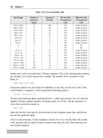
Figure 6.9 shows an example Wi-Fi Alliance certificate. Certificates for all products which
are certified by the Wi-Fi Alliance are available at the Wi-Fi Alliance’s website at http://
www.wi-fi.org.
The certificate is organized into a few sections. The Wi-Fi logo is color-coded and shows
the amendment letters corresponding to the radio types that the device supports. The letter
“a”correspondsto802.11a,“b”to802.11b,“g”to802.11g,and“n”withtheword
“DRAFT”follwingitto802.11nDraft2.0.Thecerticationdate,categoryofthedevice
(Enterprise Access Point or Phone for our purposes), manufacturer, and model number are
also available on the top.
The columns list the certifications that the device has achieved. The first column lists the
radio standards that the device has passed certification on, repeating the information in the
color-coded logo. Additionally, the amendments 802.11d and 802.11h are shown for devices
which have been submitted for the optional country code certification. The second column
shows the security specifications that the device has passed. WPA and WPA2 are shown,
each with Enterprise and Personal variations, based on what the device has passed. If the
device has passed WPA or WPA2 Enterprise, there will also be a list of EAP types that were
used. For clients, seeing an EAP type means that the client should be capable of using this
EAPtypeinlivedeployments.Currently,thislistincludesEAP-TLS,EAP-TTLSwith
MSCHAPv2 password authentication inside the tunnel, PEAPv0 with EAP-MSCHAPv2
278 Chapter 6
www.newnespress.com
inside the tunnel, PEAPv1 with EAP-GTC inside the tunnel, and EAP-SIM. Under the third
column comes, at the top, quality-of-service specifications. WMM should always be listed
for voice devices. Expect to find WMM Power Save as well, and WMM Admission Control
for devices which support it. The bottom half of the column is for special features, and is
not present in this example certificate, as those features are not typically used for
enterprises. The final column specifies voice and mobility certifications, and may contain
VoicePersonalorVoiceEnterprise.
6.3.1.1 WMM Certifications
The WMM protocol makes up the very foundation of voice over Wi-Fi. The Wi-Fi Alliance
tests WMM devices to ensure that they are able to provide that differentiation for all four
priority levels, with a battery of tests which ensure that performance is preserved based on
thepresenceofbackgroundtrafc.AllVoice-and802.11n-certieddevicessupportWMM.
The WMM Power Save certification continues by ensuring that the WMM Power Save
protocol is followed, allowing for power savings to be applied for voice mobility devices.
AllVoicedevicesareWMMPowerSave–certied.
Wi-Fi® Interoperability Certificate
Certification ID: WFA0000
This certificate indicates the capabilities and features that successfully completed interoperability testing
by the Wi-Fi Alliance. You may find detailed descriptions of these features at
www.wi-fi.org/certification_programs.php.
Certificate Date: February 1, 2009
Category: Enterprise Access Point, Switch/Controller or Router
Company: Access Point Vendor, Inc.
Product: Access Point AP-1000
Model/SKU #: AP1000-ABGN-US
This product has the following Wi-Fi Certifications:
IEEE Standard
IEEE 802.11a
IEEE 802.11b
IEEE 802.11g
IEEE 802.11n draft 2.0
IEEE 802.11d
IEEE 802.11h
Security
WPA™ - Enterprise, Personal
WPA2™ - Enterprise, Personal
EAP Type(s)
EAP-TLS
EAP-TTLS/MSCHAPv2
PEAPv0/EAP-MSCHAPv2
PEAPv1/EAP-GTC
EAP-SIM
Multimedia
WMM®
WMM Power Save
Convergence
Voice - Personal
For more information: www.wi-fi.org/certification_programs.php
Figure 6.9: Example Wi-Fi Alliance Certificate
Voice Mobility over Wi-Fi 279
www.newnespress.com
The WMM Admission Control certification tests to see that the admission control protocol
is followed by clients and access points, ensuring that clients do not seek to access
the air with priority without an admission for a resource request, or that, if they do
access the air without permission or after having exceeded their resource bounds, that they
accesstheairinanonprioritizedmanner.WMMAdmissionControlisrequiredforVoice
Enterprise–certified devices.
6.3.1.2 Voice Certifications
There are two certifications for voice within the Wi-Fi Alliance. These two programs are
both mixtures of interoperability and performance tests to ensure that voice quality is likely
to be maintained by the devices. These are the first certifications within the alliance to be
focused on a nondata application, and thus are set up in specific ways to maximize the
amount of voice testing coverage without increasing the complexity.
Both programs establish a set of observable over-the-air criteria that must be met for the
access point and the client to pass the test. Specifically, the tests require a one-way jitter
less than 50ms, from client to a wireline device connected on a low-latency network to the
access point or vice versa; a maximum jitter also less than 50ms; a packet loss rate of less
than 1%; and no more than three consecutive packet losses. These numbers are applied to
simulated voice streams, generated by the test tools to produce packets with the
approximate sizes and the exact timings of typical G.711 and G.729 encoded bidirectional
voice flows. Both programs also test for a certain number of voice calls while generating a
high-bitrate video stream, as well as an unbounded best-effort TCP data stream, to ensure
that voice quality operates well in the presence of converged applications. Devices are
placed into WMM Power Save and non–power save modes and are exercised with different
security settings to ensure a more uniform test.
TheVoicePersonaltestincludeshavingfourvoiceclientssimultaneously,andallfour
clients must have voice flows that pass the above criteria for the test to pass, even if only
one of the four clients is a voice client being certified. (The rest are already-certified devices
beingusedtotestwith.)Furthermore,theVoicePersonalcerticationrequiresthatdevices
already be certified for WPA2 Personal, WMM, and WMM Power Save. The test is
primarily focused on consumer-grade devices, but a small handful of enterprise-grade
vendorshavealsopassedtheVoicePersonaltest,allowingawiderrangeofcertiedphones
to potentially be paired with the network, if certification is desired for both sides.
TheVoiceEnterprisetestismoreappropriateforvoicemobilitynetworks.Basedonthe
VoicePersonaltest,theVoiceEnterprisetestincreasesthedensityofvoiceclientsfrom
four to ten. More interestingly, however, is that it includes portions of 802.11k (Section
6.2.6) and 802.11r (Section 6.2.5), to increase the chances of handoff success. The 802.11k
and other measurement features publicly mentioned as important foundations for the
certification, as of the time of this writing are: